-
Paper Information
- Next Paper
- Previous Paper
- Paper Submission
-
Journal Information
- About This Journal
- Editorial Board
- Current Issue
- Archive
- Author Guidelines
- Contact Us
International Journal of Aerospace Sciences
p-ISSN: 2169-8872 e-ISSN: 2169-8899
2013; 2(1): 11-15
doi:10.5923/j.aerospace.20130201.02
Deflection of Structures using Modified Betti’s Theorem
 Abstract
 Reference
 Full-Text PDF
 Full-text HTML
Inder Krishen Panditta
Mechanical Engineering Department, N .I. T. Srinagar, J&K, 190006, India
Correspondence to: Inder Krishen Panditta, Mechanical Engineering Department, N .I. T. Srinagar, J&K, 190006, India.
| Email: |  |
Copyright © 2012 Scientific & Academic Publishing. All Rights Reserved.
In this paper, Betti’s theorem is modified by inclusion of constraint reactions in the set of externally applied loads. Based on this, a new methodology for calculating deflections of any structure is presented in this paper. The methodology has an advantage over the conventional methods due to the fact that deflections of a structure for any general loading and for different boundary conditions are calculated mostly by simple multiplications. It does not require the knowledge of writing internal force/ moment expressions. The methodology leads to a unique concept of reference structural element. Equation of deflected elastic curve of the reference element is utilized to obtain equation of deflected elastic line of the structure with any other type of loading and boundary conditions. Present methodology is fast and easy in its use especially when the structure is loaded by a series of point loads. Even for distributed loads a simple integration of a priory known polynomial integrands leads to the result. This methodology is applicable to any class of structure as long as a reference element is defined for that class. Here, this methodology is illustrated for beams.
Keywords: Betti’s Theorem, Reciprocal Theorem, Indeterminate Beams, Modified Betti’s Theorem
Cite this paper: Inder Krishen Panditta, Deflection of Structures using Modified Betti’s Theorem, International Journal of Aerospace Sciences, Vol. 2 No. 1, 2013, pp. 11-15. doi: 10.5923/j.aerospace.20130201.02.
Article Outline
1. Introduction
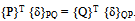
- Various methods exist for calculation of deflection/ deformation of structures which include energy methods ([1-2]), variational principles ([3-4]) and finite element methods ([5-6]). Take the case of beams, in conventional methods deflection of a beam is obtained invariably by using Internal Bending Moment (IBM) expression. For example, in double integration method IBM expression is to be integrated twice followed by evaluation of constants ([7]), in Castigliano’s method single integration of the square of IBM is to be carried out followed by partial derivative with respect to the desired load ([8]), in Unit Load Method one has to integrate the product of IBM expression for the given load and IBM expression due to unit load ([9]). One does not have to work with internal force/ moment expressions if Betti’s theorem is used after modifying it by including support reactions in the set of applied loads.Betti’s theorem, given by Enrico Betti in 1872 relates two systems of loads acting on an elastic body. It states that for a linear elastic body subjected to two different sets of forces {P} and {Q}; work, WPQ, done by {P} while going through the displacements, {δpq}, due to {Q} is equal to work, WQP, done by {Q} while going through the displacements, {δqp}, due to {P}. This theorem has been used by several authors for solving different problems of structural mechanics. Using this theorem, closed form solution for the displacement of inclusion problems was given by[10], singular stress field in the neighbourhood of notches and corners in anisotropic media was derived by[11] and the theorem was applied to elastic infinite space bounded by rigid inclusions by[12]. Selected problems of the elastic half-space were successfully solved by using reciprocal theorem by[13] and Betti’s reciprocal theorem was applied to deformed bodies with different constitutive relations by[14]. In this paper, Betti’s theorem is modified by including reactions from supports as part of the applied loading and a new methodology based on modified Betti’s theorem is presented for getting deflection of any structure without using internal force/ moment expressions. It is much easier and faster as work done by external loading is calculated by multiplication of given loads acting on a given structure with the corresponding known displacements due to a chosen load vector on the structure and no integrations are involved if concentrated loads are acting on the given structure. Even for distributed loads integration of the product of two a priory known polynomial integrants (expression for the given distributed load and equation of deflection curve due to chosen load) is easy.This methodology leads to a unique concept of reference structural element on which a conveniently chosen set of self equilibrating load is acting. With the help of the equation of its deflection curve, solution for deflection of the structure with different boundary conditions and for any other type of loading can be obtained. As the reference element remains same for a class of structures, this paves way for the development of a general purpose interactive graphic computer package for calculating deflections of a structure (belonging to the same class) with any general type of loads as well as with different boundary conditions. Betti’s theorem may be considered as a highly restricted form of principle of quasi work in which two systems are taken as topologically identical[15 – 19]. Whereas, modified Betti’s theorem can be regarded as a restricted form of principal of quasi work in which two structural systems are taken to be topologically equivalent systems[15 – 19].In the next section, the modified Betti’s theorem is proved. In the subsequent sections the new methodology is developed and illustrated for beams.
2. Proof of Modified Betti’s Theorem
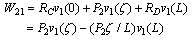
- Let two self equilibrating set of forces {P} and {Q} act on a structural system. In these sets some of the forces can be considered as reactions. This widens the scope of Betti’s theorem as a structure with different boundary conditions along with different set of loads can be related.As strain energy stored in the system does not dependent on the order in which loads are applied to the structure. There are two possible ways of applying self equilibrating set of loads {P} and {Q} on the structure. In the first case, load set {Q} is applied after the application of the load set {P}. In this case, Strain energy, U1, stored in the structure is equal to:
 | (1) |
 | (2) |
 | (3) |
 | (4) |
3. Reference Structure
- As this methodology is based on modified Betti’s theorem (MBT), therefore, two sets of loads for the same structure should be given. One set of loads acting on a given structure is predefined and other set is to be chosen by analyst. This chosen set of self equilibrating loads acting on the structure should remain same for all given problems. It is of interest to observe that the structure in MBT does not include supports. Hence, both loading and support conditions have to be defined for the reference structure. Here, this concept is illustrated for beams and an attempt has been made to define such a beam. This beam will be referred to as Reference Beam (RB). A simply supported beam ‘CD’ carrying a point load ‘P2’ acting downwards at a distance of ζ from the left end ‘C’, shown in Fig.1, is taken as RB. Its material and geometrical properties will be same as that of the given beam. Let these properties be E, I and L.
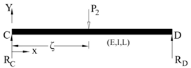 | Figure 1. Reference Beam |
 | (5) |
4. Application to Beams
- In what follows are illustrative examples of the application of present methodology for obtaining equation of deflected elastic curve of beams and also for calculating the deflection at a point in a given beam. Examples include determinate and indeterminate beams with different boundary conditions carrying point as well as distributed loads. In these illustrations loads and corresponding deflections of the given beam will be denoted by subscript ‘1’.
4.1. Illustration – 1: S. S. Beam Partly Uniformly Loaded
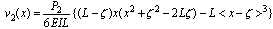
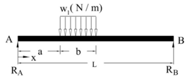
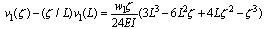
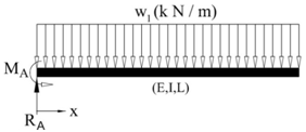
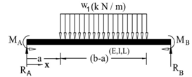
- Equation for deflected elastic line of a simply supported beam ‘AB’ carrying a uniform load of ‘w1’ N/m as shown in Fig.2 is derived. The load acts from ‘a’ meters to ‘(a + b)’ meters as measured from the left end.
 | Figure 2. Partly Loaded S. S. Beam |
 | (6) |
 | (7) |
 | (8) |
4.2. Illustration – 2: S. S. Beam with Point Loads
- In this example one can observe that for point loads only evaluation of algebraic expression (summation of the product of two numbers) is required which definitely is much simpler than what existing conventional methods offer.A simply supported beam ‘AB’ of length 8m carrying two point loads and an end moment as shown in Fig.3 is taken up for calculating deflection under the load of 64kN acting downwards at a distance of 1m from the left end ‘A’ of the beam. Other loads acting on the beam are taken as a point load of 48kN acting downwards at a distance of 4m from end ‘A’ and a clockwise moment of 10kN.m acting at the right end ‘B’ of the beam. The value of young’s modulus of elasticity, E= 210 GPa and second moment of cross sectional area, I = 180 x 106 mm4.
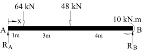 | Figure 3. S. S. Beam with Point Loads |
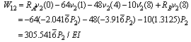 | (9) |
4.3. Illustration – 3: Deflection of a Beam with Overhang
 | Figure 4. Beam with overhang |
 | (10) |
 | (11) |
 | (12) |
4.4. Illustration – 4: Cantilever Beam with Uniform Load
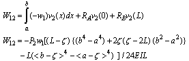
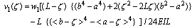
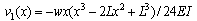
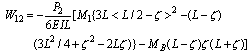
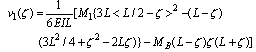
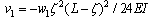
- In this illustration deflection equation of elastic curve of a cantilever beam, ‘AB’ shown in Fig.5, with parameters E, I, L and carrying a uniform load, ‘w’ N/m, over its full span is obtained. W12 and W21 are given by:
 | (13) |
 | (14) |
 | (15) |
 | Figure 5. Cantilever Beam with uniform load |
 | (16) |
4.5. Illustration - 5: Deflection of Single Degree Indeterminate Beam
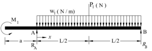
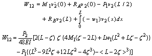
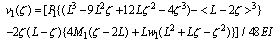
- In this illustration, equation for deflected neutral axis of indeterminate beam ‘AB’ supported by a roller at the left end ‘A’ and built-in at right end ‘B’ is obtained. Beam has parameters L, E, I and carries an anticlockwise moment ‘M1’ at its midpoint as shown in Fig.6 wherein RA, RB and MB are reactions from supports. Parameters of RB in Eqn.(5) are chosen to be same as those of the given beam parameters (E, I, L).
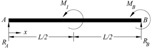 | Figure 6. Tip Supported Cantilever Beam |
 | (17) |
 | (18) |
 | (19) |
4.6. Illustration – 6: Two Degree Indeterminate Beam
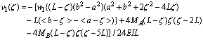
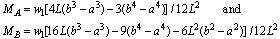
- Equation of the deflected elastic line of a beam ‘AB’ built in at both ends, as shown in Fig.7, having parameters E, I, L and uniformly loaded from a distance ‘a’ to a distance ‘b’ from the left end ‘A’ is obtained in this illustration.
 | Figure 7. Built - in Beam with UDL |
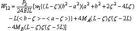 | (20) |
 | (21) |
 | (22) |
 | (23) |
5. Conclusions
- 1) Betti’s theorem is successfully modified by treating reactions from constraints as a part of external loading. 2) Using modified Betti’s theorem, deflection at any point of a given beam or the equation of its deflected elastic line is successfully obtained without using internal bending moment expressions.3) A reference beam is defined by choosing its loading and boundary conditions. Equation for its deflected elastic line is successfully used to solve all other beam problems irrespective of their loading and boundary conditions.4) Obtaining deflection at a point or equation of deflected elastic line of any given beam becomes easy and simple by using present methodology. 5) It is further simplified if given problem has only point loads as the solution is obtained by simple multiplications. In this case neither integration nor differentiation is required.6) As reference beams is used to solve all other beam problems with different loads and different constraints, it is possible to develop an interactive graphic general purpose computer package for this purpose.7) This method is a general one and can be used to solve any other class of structural problems as long as a reference structural element for that class of structures is defined.