-
Paper Information
- Previous Paper
- Paper Submission
-
Journal Information
- About This Journal
- Editorial Board
- Current Issue
- Archive
- Author Guidelines
- Contact Us
International Journal of Aerospace Sciences
p-ISSN: 2169-8872 e-ISSN: 2169-8899
2013; 2(1): 16-28
doi:10.5923/j.aerospace.20130201.03
Static Analysis of Laminated Piezoelectric Cylindrical Panels
 Abstract
 Reference
 Full-Text PDF
 Full-text HTML
J. E. Jam1, S. Maleki2, A. Andakhshideh2
1Composite Materials and Technology Center, MUT, Tehran, Iran
2Department of Mechanical Engineering, Faculty of Engineering, Ferdowsi University of Mashhad, Mashhad, Iran
Correspondence to: J. E. Jam, Composite Materials and Technology Center, MUT, Tehran, Iran.
| Email: |  |
Copyright © 2012 Scientific & Academic Publishing. All Rights Reserved.
The Static analysis of laminated piezoelectric cylindrical shells with various boundary conditions is presented employing Generalized Differential Quadrature (GDQ) method. The first-order shear deformation theory (FSDT) is considered to model the static response of panel. Different symmetric and asymmetric lamination sequences together with various combinations of clamped, simply supported and free boundary conditions are considered. Particular interest of this study regards to asymmetric piezoelectric orthotropic cylindrical panels having free edges and subjected to general electromechanical loading. Taking into account the effects of shear deformation and initial curvature, a system of fifteen first order partial differential equations (PDEs) in terms of unknown displacements, rotations, moments and forces is developed. Several numerical examples are presented to demonstrate the accuracy and convergence of the proposed method with relatively small number of grid points. It is also revealed that the present method offers similar order of accuracy for all variables including displacements and stress resultants. Further results for panels with particular boundary conditions are provided which can be used as benchmarks in future.
Keywords: Static Analysis, Piezoelectric Cylindrical Panel, Asymmetric Cross-ply Laminates, Generalized Differential Quadrature, Various Boundary Conditions
Cite this paper: J. E. Jam, S. Maleki, A. Andakhshideh, Static Analysis of Laminated Piezoelectric Cylindrical Panels, International Journal of Aerospace Sciences, Vol. 2 No. 1, 2013, pp. 16-28. doi: 10.5923/j.aerospace.20130201.03.
Article Outline
1. Introduction
- Laminated Piezoelectric structures have found wide applications as key structural elements due to enhanced electro-mechanical characteristics[1-7]. In particular, bending, buckling and vibration of laminated piezoelectric cylindrical panels subjected to various combinations of loading and boundary conditions have been the main subject of many investigations[8-15]. It is well-known that analytical methods are only applicable to particular types of boundary conditions such as panels with at least two opposite sides simply supported. In this regard, Chen et al.[16] presented an exact elasticity solution for an orthotropic cylindrical shell with piezoelectric layers. Kapuria et al.[17] demonstrated similar study to obtain an analytical solution for free vibration of simply supported piezoelectric laminated circular panels in cylindrical bending. They employed a layerwise expanding in Fourier series together with the modified Frobenius method. Daneshmehr et al.[18] investigated dynamic response of cross-ply laminated panels with a piezoelectric layer. They found a three-dimensional elasticity solution for finitely long, simply-supported shell panels. In this paper the highly coupled partial differential equations reduced to ordinary differential equations with variable coefficients by means of trigonometric function expansion in circumferential and longitudinal directions. This method also applied to functionally graded piezoelectric (FGP) cylindrical shell panels under pressure and electrostatic excitation, recently [19]. So, in the range of analytical solutions one can find similar studies for laminated piezoelectric cylindrical panels and shell, while they are all limited to special cases of geometries, simplified theories and boundary conditions. Thus, numerical techniques, as alternatives to analytical approaches, have been developed to obtain solutions for different structural components subjected to various types of loading and boundary conditions. Among these numerical studies, one can refer to boundary element[20], dynamic relaxation[21], extended Kantorovich method[22], various meshless methods[23], differential quadrature method (DQ)[24-25], differential cubature method (DC)[26], and generalized differential quadrature (GDQ)[27]. In this paper, the GDQ method is employed to obtain a solution for static analysis of laminated cylindrical panel with piezoelectric layers. General laminate layups and any combination of various boundary conditions are considered. Accuracy and rapid convergence of the method are examined with various examples. Of particular interests in this study are panels with free edges under electromechanical loading, whereas similar results are not found in the open literature to the best of authors' knowledge. Predictions of the presented method for various stress and displacement components exhibit a good agreement compared with other solutions.
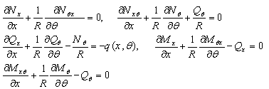
2. Governing Equations
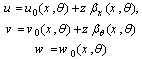
- Consider a piezoelectric laminated cylindrical panel with length a, mean radius R, total angle α and total thickness h as shown in Figure 1. The curvilinear coordinate system is located on the mid-surface of the laminate. The coordinates in the longitudinal, tangential and radial directions are designated by x, θ, and z, respectively and are depicted in Figure 1. According to the first order shear deformation theory, the displacement field can be written as:
 | (1) |
 and
and  denote the displacements of the middle surface,
  and
and  are the rotation of tangents to the middle surface. Strain-displacement relations for a cylindrical shell in terms of cylindrical coordinates can be expressed as:
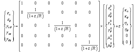 | (2) |
 | (3) |
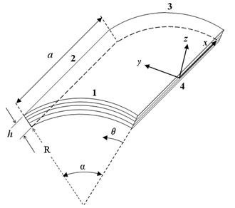 | Figure 1. Geometry of the panel |
 and
and  are the normal strains,
  and
and  are the in-plane shear strains,
  and
and  are the change in the curvature,
  and
and  denote the torsion,
  and
and  are the shear strains of the referenced mid-surface. Subscript comma denotes the differentiation with respect to x or 𝜃The stress-strain relations for the kth layer of the general laminated piezoelectric cylindrical panel in the laminate coordinate system can be expressed as follows[28-29],
 | (4a,b) |
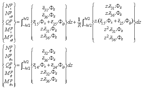
 are the transformed stiffness components of the kth layer,
  are the transformed piezoelectric moduli,
  is the applied voltage across the kth layer and
 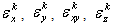 are dielectric coefficients of the kth layer.In-plane stress resultants
  , couple resultants
  and transverse shear force resultants
  can be determined by integration of the relevant stress components over the entire thickness of the panel as below:
 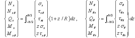 | (5) |
 and
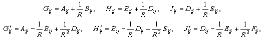
and  , unless the term z/R is ignored. This is due to the difference in the radii of curvature in two perpendicular directions. Finally, constitutive equations for general laminated cylindrical panels in terms of displacement and rotation components can be derived as:
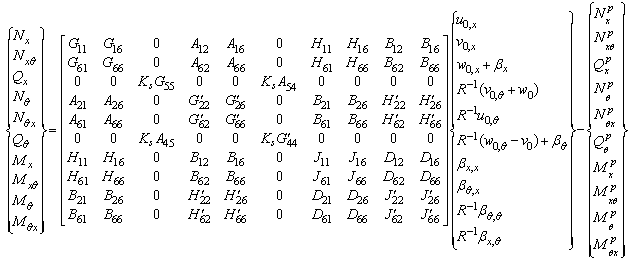 | (6a) |
 | (6b) |
 | (7a) |
 | (7b) |
 | (8) |
 | (9) |
 | (10) |
 | (11) |
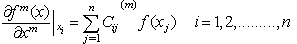
3. Application of the GDQ
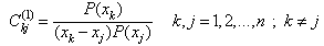
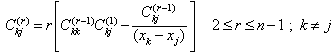
- The GDQ method is employed to solve the developed differential equations of the laminated piezoelectric cylindrical panels. The essence of the GDQ method is that the partial derivative of a function with respect to a variable is approximated by a weighted sum of function values at all discrete points in that direction. Considering a function f(x) with n discrete grid points[31], we have
 | (12) |
 | (13) |
 | (14) |
 | (15a) |
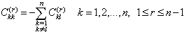 | (15b) |
 | (16) |
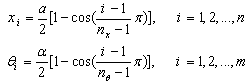
 are geometric parameters of the panel shown in Figure 1. The next step is to discretize the governing equations based on the definition given in equation (12). Thus, the discretized form of the governing equations at a sample grid point (i,j) can be written as:
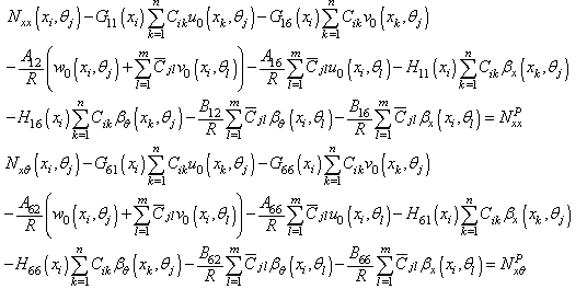

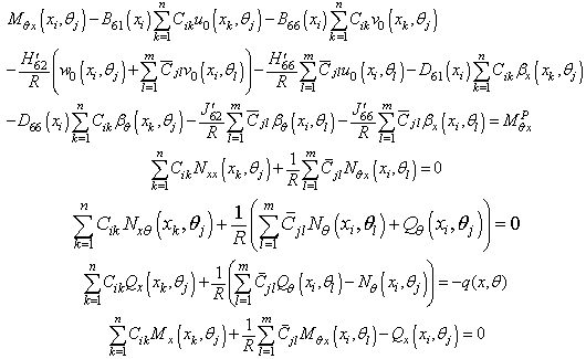
 | (17) |
4. Results and Discussion
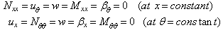
- The presented algorithm is employed to solve the governing equations of static analysis for laminated orthotropic cylindrical panels integrated with piezoelectric layers. In this study the effects of different types of boundary conditions are investigated. Three general types of loadings are considered: electrical, mechanical and electromechanical. A plate with SCFS boundary conditions means that sides 1, 2, 3, 4 (see Figure 1) are simply supported, clamped, free and simply supported, respectively.
|
 , q0=1) of infinitely long cylindrical panel with one composite layer
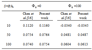
 , the panel radius is R=1 and the panel total angle is equal to
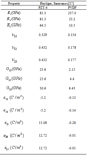
  . The Piezoelectric layers are assumed to be elastically isotropic and uniaxially polarized with the material properties of:
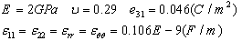 | (18) |
 | (19) |
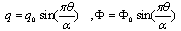 where q0 and Φ0 are the peak value. The voltage is applied to the upper surface of the actuator, while the voltage of the actuator interface and the sensor surfaces are assumed to be zero. It is seen that the predicted normalized transverse displacements are in good agreement with those reported by Ref.[16].
|
 , q0=1) of infinitely long cylindrical panel with three composite layers
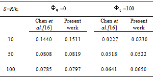
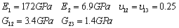
 is considered. Material properties of the panel are:
  ,
,
 and the geometry parameters are set to be: (a=4, R=1,
  , S=R/h=50). The normalized central deflection and stresses for both symmetric (90/0/90) and asymmetric cross ply (0/90) layups are presented in Table 3. In both cases the layers are of equal thickness. The normalized transverse deflection and stresses are defined as follows:
 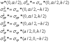 | (20) |
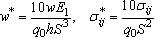 | (21) |
|

|
4.1. Electrical Loading
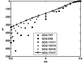
- In order to show the convergence of the present work, the non-dimensional deflection of the piezoelectric panel is presented for different types of boundary conditions in Figs. 3 through 5. The polarization of PVDF layers (see Figure 2) are reversed and the electrical/mechanical parameters of the loading are considered to be
 . The deflections are reported on the central circumferential line of the panel
  and are calculated from expression
 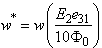 in terms of PZT-4 properties. The boundary conditions of the panels are FCFF, FCCF and CCFC in Figs. 3-5, respectively. It is obvious that the free type boundary conditions exhibit the worst convergence characteristic than the others. It is found that the use of seventeen grid points in the x and directions respectively can provide accurate numerical results. This guarantees faster rate of convergence of the method for other types of boundary conditions.
  | Figure 2. Laminates layup and electrical loading of piezoelectric layers |
 | Figure 3. Normalized deflection  of cantilever piezoelectric laminated cylindrical panels under electric loading of cantilever piezoelectric laminated cylindrical panels under electric loading at at  |
 | Figure 4. Normalized deflection  of FCCF piezoelectric laminated cylindrical panels under electric loading of FCCF piezoelectric laminated cylindrical panels under electric loading at at  |
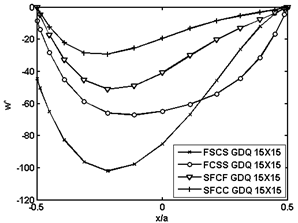
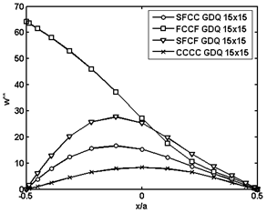
 of the piezoelectric laminated cylindrical panel with various boundary conditions along x axis at
  . It is realized that the solution characteristics of the method is dependent on the boundary conditions. It is also seen that the locations of the maximum deflections are dependent on the type of boundary conditions. Although, the maximum deflection naturally occurs at the center of the fully simply supported panel, its location is not evident for other boundary conditions.
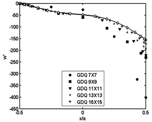 | Figure 5. Normalized deflection  of CCFC piezoelectric laminated cylindrical panels under electric loading of CCFC piezoelectric laminated cylindrical panels under electric loading at at  |
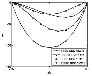 | Figure 6. Normalized deflection  of piezoelectric laminated cylindrical panels with various boundary conditions under electrical loading of piezoelectric laminated cylindrical panels with various boundary conditions under electrical loading at at  |
 | Figure 7. Non-dimensional deflection  of piezoelectric laminated cylindrical panels with free edges under electrical loading of piezoelectric laminated cylindrical panels with free edges under electrical loading at at  |
4.2. Mechanical Loading
- The normalized transverse deflection
 of the piezoelectric laminated cylindrical panel under uniform lateral mechanical loading
  is illustrated in Figs. 8 and 9. The normalized deflection is defined as
  in terms of PZT-4 properties. Again various boundary conditions are considered and the deflection of panel is reported on the central circumferential line. The results show that clamped edges effectively reduce the deflection especially while they are adjacent to free edges in comparison to opposite free and clamped sides.
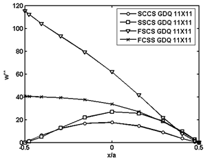 | Figure 8. Non-dimensional deflection  of piezoelectric laminated cylindrical panels with free edges under mechanical loading of piezoelectric laminated cylindrical panels with free edges under mechanical loading at at  |
 | Figure 9. Normalized deflection  of piezoelectric laminated cylindrical panels with various boundary conditions under mechanical loading of piezoelectric laminated cylindrical panels with various boundary conditions under mechanical loading at at  |
4.3. Electromechanical Loading
- The last part of the results is dealt with the general type of electromechanical loading
 . Figure 10 depicts effects of the aforementioned boundary conditions on the non-dimensional deflection
  of the piezoelectric laminated cylindrical panel under this type of loading. The normalized transverse deflection is also expressed in terms of the piezoelectric material properties as
  .
.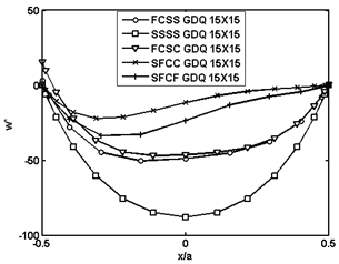 | Figure 10. Normalized deflection  of piezoelectric laminated cylindrical panels with various boundary conditions under electromechanical loading of piezoelectric laminated cylindrical panels with various boundary conditions under electromechanical loading at at  |
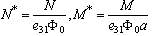 , where
  is the PZT-4 property. It can be seen that the largest stress resultants occur in the panels having SSSS boundary condition. On the other hand, the stress resultants are at their lowest value for the CCCC case.
 | Figure 11. Non-dimensional stress resultants  of piezoelectric laminated cylindrical panels under electromechanical loading of piezoelectric laminated cylindrical panels under electromechanical loading at at  |
 | Figure 12. Normalized moment resultants  of piezoelectric laminated cylindrical panels under electromechanical loading of piezoelectric laminated cylindrical panels under electromechanical loading at at  |
5. Conclusions
- The applicability and efficiency of the GDQ method are investigated for static analysis of piezoelectric laminated cylindrical panels. The procedure permits a systematic and a straightforward modeling of mixed boundary conditions. Numerical predictions are presented for deflection, stresses and resultant forces with different types of boundary and various numbers of grid points. Of particular interests in this study are panels with free edges and general electromechanical loading which similar results are not found in the open literature. Presence of all parameters including displacements, rotations and stress resultants in the governing equations provides a simple procedure to handle any boundary conditions without any difficulty. Furthermore, it results in the same order of accuracy for all parameters including stress components.