-
Paper Information
- Next Paper
- Paper Submission
-
Journal Information
- About This Journal
- Editorial Board
- Current Issue
- Archive
- Author Guidelines
- Contact Us
International Journal of Aerospace Sciences
p-ISSN: 2169-8872 e-ISSN: 2169-8899
2013; 2(1): 1-10
doi:10.5923/j.aerospace.20130201.01
Design of a Sliding Mode Control for Wing Rock Suppression in Highly-Swept Wing Aircraft
 Abstract
 Reference
 Full-Text PDF
 Full-text HTML
Giorgio Guglieri, Daniele Sartori
Department of Mechanical and Aerospace Engineering, Politecnico di Torino, Torino, 10129, Italy
Correspondence to: Daniele Sartori, Department of Mechanical and Aerospace Engineering, Politecnico di Torino, Torino, 10129, Italy.
| Email: |  |
Copyright © 2012 Scientific & Academic Publishing. All Rights Reserved.
Wing rock is an oscillatory rolling motion which arises at high angles of attack in aircraft with highly-swept wings. In the present paper, a method to suppress wing rock through sliding mode control is proposed. Sliding mode control is designed to minimize together roll angle error and command input through a cost function. The procedure is performed on a wing-only analytical model, the controller is then applied to a complete wing-fuselage model. Simulations include different angles of attack and robustness is assessed using a model altered by parametric disturbances. Results are compared with the behavior obtained by a conventional roll damper.
Keywords: Wing Rock, Flight Mechanics, Sliding Mode Control, Roll Damper
Cite this paper: Giorgio Guglieri, Daniele Sartori, Design of a Sliding Mode Control for Wing Rock Suppression in Highly-Swept Wing Aircraft, International Journal of Aerospace Sciences, Vol. 2 No. 1, 2013, pp. 1-10. doi: 10.5923/j.aerospace.20130201.01.
Article Outline
1. Introduction
- Sliding mode control (SMC) is a form of Variable Struc- ture Control (VSC). SMC is a nonlinear control method that alters the dynamics of a nonlinear system by the application of a high-frequency switching control. The state-feedback control law is not a continuous function of time. In fact, it switches from one continuous struc- ture to another based on the current position in the state space. VSC systems are defined by a feedback control law and a decision rule [1]. The decision rule generates the feedback controller according to the assumed switching function and to the current state of the system. In sliding mode control the controller is designed to force the system state trajectories to move towards a region of the state space (sliding surface). When the sliding sur- face is reached, the resulting motion (sliding motion) is constrained to remain in a neighborhood of this region. The system slides along it until it achieves the desired equilibrium point. As the control law is a discontinu- ous function, the sliding motion can be reached in finite time. When the sliding motion occurs, the system becomes insensitive to matched internal and external dis- turbances.VSC and SMC theory is based on the work developed in the 1960s by Soviet scientists Emelyanov [2] [3] and Barbashin [4] [5] [6]. The contribution of Aizerman [7] [8], Itkis [9] and in particular Utkin (for instance [10] [11] [12] [13] [14]) helped the diffusion of this technique. Ap- plications of sliding mode control include robotics [15] [16], power systems [17] [18] [19], aircraft control [20] [21] and many others. Sliding mode method solves many of the disadvantages of designing a nonlinear control sys- tem. In fact, as well described by [22], commonly the nonlinear design procedure consists in applying a lin- ear control law to a system linearized about an operat- ing point. Such a controller does not guarantee optimal performance, in particular when the system state is far from the design condition. SMC, instead, allows syn- thesis of high order MIMO nonlinear systems (a good tutorial is represented [23]). Other advantages include robustness against matched uncertainties and external disturbances and the possibility to design a switching function tailored to the desired behavior. On the con- trary, the chattering phenomenon, an oscillatory motion about the sliding surface, is a considerable drawback. It can cause low control accuracy, energy loss, high wear of moving mechanical parts, plant damage and excitation of unmodeled dynamics [18] [24].In this paper a sliding mode controller is designed to suppress the wing rock, a flight mechanics phenomenon. Wing rock is an oscillatory rolling motion of an aircraft which occurs at high angles of attack. The main aerody- namic parameters of wing rock are: (i) angle of attack (ii) angle of sweep (iii) leading edge extensions (iv) slen- der forebody. Therefore, the aircraft that are susceptible to the wing rock phenomenon are those containing these parameters; such as aircraft with highly swept wings operating with leading edge extensions. The motion is characterized by an increase in amplitude up to a limit cycle; the final state is usually stable and defined by large roll oscillations. The onset of wing rock is related with a nonlinear variation of roll damping with angles of attack and sideslip, oscillation frequency and amplitude. The control of wing rock is a relevant issue as high-speed civil transport and combat aircraft can encounter it in their flight envelope, seriously compromising handling qualities and maneuvering capabilities.Different controllers have been proposed to suppress wing rock oscillations. Cao [25] used an adaptive con- troller, while Liu (for instance [26][27][28]) adopted dif- ferent approaches applied to the same analytical model. Another reference ([29]) dealing with nonlinear syner- getic optimal controllers applies this technique for the suppression of wing rock. An interesting paper by Lin and Hsu [30] compares Supervisory Recurrent Fuzzy Neural Network Control (SRFNNC) with SMC for wing rock control. The authors demonstrate the superiority of trained SRFNNC in tracking a reference signal, while untrained SRFNNC compared to SMC shows larger transient responses and control effort. A more com- plex controller is proposed by the same authors in [31]. Equipped with a Robust Adaptive Fuzzy Sliding Mode Control (RAFSMC) feature, robustness and automatic adjustment of fuzzy rules are guaranteed.The choice of SMC for the design of a wing rock sup- pression system is motivated by several considerations. The wing rock model is nonlinear with quite large parametric changes in the angle of attack range: amplitude and frequency of the oscillatory limit cycle, and the related coefficients of the parametric model, change quite significantly. SMC exhibits low sensitivity to plant pa- rameter uncertainty and, generally, it requires greatly reduced-order modeling of plant dynamics. Further- more, robustness is a prerequisite to withstand model uncertainties. As a matter of fact, wing rock dynamics is dominated by wing-body vortical patterns, aerodynamic asymmetries and other sources of couplings, such as unsteady interaction between primary forebody vor- tices and lifting surfaces (wing and stabilizers). The forebody-induced wing rock may be suppressed either by changing forebody cross-section and slenderness or by the adoption of forebody vortex control techniques such as movable forebody strakes (see Figure 1) or bound- ary layer suction-blowing [34]. This type of control devices differ from conventional trailing edge control, such as ailerons, and operate in a way that is more compatible with the features of SMC controllers (high-frequency switching control). Finally, SMC provides convergence within a finite time horizon, a vital feature during some aircraft maneuvers.In this paper a simple SMC controller for wing rock suppression is designed on a plain wing analytical model. The parameters of the model reflect the result of extensive wind tunnel experimental tests. The controller is designed so that a cost function with roll angle error and control input is minimized. The resulting controller is applied to a complete wing-fuselage analytical model under a large set of angles of attack and parametric uncertainties. Similar simulations are performed with a conventional roll damper optimized to minimize both the roll angle error and the aileron deflection. The authors seek to demonstrate that such a controller is able to cancel wing rock oscillations in all conditions with satisfactory results.
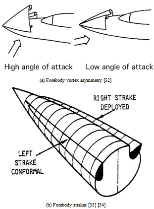 | Figure 1. An example of forebody vortex control device. |
2. Wing Rock Model
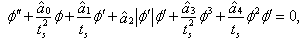
- The considered analytical model was derived and exper- imentally validated in [35] and [36]. The experimental tests were carried out in the D3M low speed wind tunnel at Politecnico di Torino. The nondimensional differential equation (single degree of freedom roll dynamics) which describes the free motion of the roll angle φ is
 | (1) |
 are the parameters relative to the xperiment conditions (i.e. angle of attack, Reynolds number and wing characteristics). The time derivatives are nondimensional.The restoring moment
  exhibits a typical trend with softening of linear stiffness
  (Duffing equation). As a consequence, the system is statically divergent for
  . The damping coefficient
  is nonlinear and negative for
  (Van der Pol equation). The system is dynamically unstable for lower roll angles and becomes stable as ∅ increases up to the inversion point. The coordinate for this dynamic stability crossover is not coincident with limit cycle amplitude, as the stability of final state occurs when
 | (2) |
 (hydraulic damping).Two experimental models were tested in the wind tun- nel, see Figure 2. Model A has span b = 0.169 m, root chord cr = 0.479 m and sweep Λ = 80° . Model C is 0.568 meters long with other wing characteristics remaining unchanged. Tests included free to roll conditions with airspeed V = 30 m/s (Re = 950000) and angle of attack α ranging from 25° to 45° .
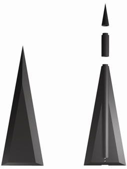 | Figure 2. Conguration models A (left) and C (right) tested in the wind tunnel. |
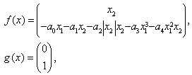
 i.e. even for initial conditions external to the final limit cycle. The phenomenon is dominated by nonlinear damping. A simulation of the roll angle time history for model A, based on the analytical model developed in [35] and [36], is presented in Figure 4 for an angle of attack
  . Small initial disturbances (
 and
and  ) are able to trigger the wing rock motion and after a few seconds the final oscillatory behavior is achieved.
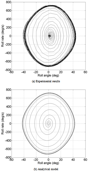 | Figure 3. Phase plane free motion for model A; α=32.5°;∅0=1°;∅0=0°/s |
 prevents the build up of oscillations; in all other cases when these are trig- gered the limit cycle is unaffected. Forebody vortices asymmetry can result in a steady state roll angle offset up to ∆∅=20° . Differently, steady state roll angle offset for model A was nonexistent. A detailed and compre- hensive analysis of the behavior of the two models can be found in [37].
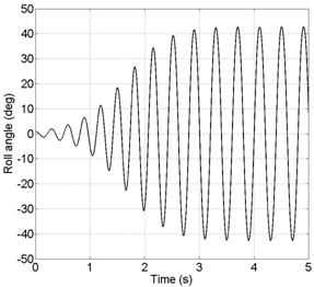 | Figure 4. Roll angle free motion for model A; α=32.5°;∅0=1°;∅0=0°/s |
3. Controller Synthesis
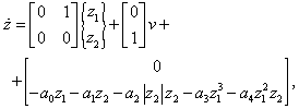
- Introducing the reference time ts = b/2V , Equation (1) becomes
 including
  in the
  coefficients it is possible to rewrite the wing rock model equation with dimensional derivatives
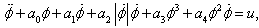 | (3) |
 | (4) |
 | (5) |
 and
and  is the state vector.
 | Figure 5. Roll angle free motion for model C; α=32.5°;∅0=1°;∅0=0°/s |
 with state z and controller
  .
.
|
 which in a more compact form can be expressed as
 and
and  are controllable matrices, the vector ω(t, z) represents the uncertainties of the equiva- lent system. The integral sliding surface for the equiva- lent linear system is chosen as
 | (6) |
 satisfies that GB is nonsingular, z(0) is the initial condition vector,
  is a positive definite matrix,
  is the solution of the matrix Riccati equation
 | (7) |
 is a symmetric positive definite ma- trix. The sliding surface s(x, t) for the original nonlinear system is obtained substituting the transformation z = T (x) in Equation (6). Its derivative in time is ex- pressed in general terms as
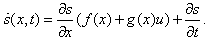 The controller u of the nonlinear system is composed of two terms, a continuous term
  and a discontinuous one
  so that
  . The continuous part is obtained imposing
  , the result is
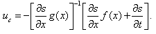 | (8) |
 stabilizes the system and drives its trajectories parallel to the sliding surface
  . In order to force them towards the sliding surface and to eliminate the effect of uncertainties the discontinuous control law is selected
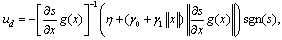 | (9) |
 and
and are positive constants.The behavior of the SMC is compared with that of a much simpler controller, a proportional roll damper, commonly used in aircraft Stability Augmentation Sys- tems (SAS). Hence, a controlling torque T is included in Equation (3) so that
  | (10) |
 kg m2 is the inertia of the model,which can be considered constant between model A and model C. The torque is modeled as
 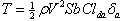 where ρ = 1.225 kg/m3 is the air density, S = 0.0405 m2 is the wing surface and Clda=-0.1 is the derivative of the roll moment coefficient with respect to the aileron deflection angle δa . The aileron deflection angle is con- sidered proportional to the roll rate, δa=kts∅ , where ts is introduced for dimensional reasons.
4. Implementation and Simulation Results
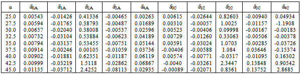
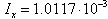
- The aerodynamic parameters
 of Equation (1) are found with least-squares approximation of wind tunnel experimental results (refer to Table 1.The matrices G∈Rm×n and R∈Rm×n of Equation (6) are chosen asG=[0,1],R=[1]P∈Rm×n is the solution of the Riccati equation (7)
 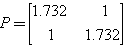 where Q∈Rn×n is assumed to be an identity matrix. The parameters η, γ0 and γ1 of Equation (9) are chosen unitary.An optimization procedure is performed in order to identify an optimal parameter for the SMC controller. A cost function considering the roll angle error and the control input is used, fSM C = τ φ2 + (1 − τ )u2 . A similar design is carried out for the roll damper, here the cho- sen function is fk = τ φ2 + (1 − τ )δa 2 where the aileron deflection angle is considered. The value of τ is set for both models to 0.8 in order to give more importance to the tracking capability of the controller. The opti- mized parameters are a gain kQ multiplying the identity matrix Q of Equation (7) for SMC and the constant k which defines δa for the roll damper. All optimizations are performed on model A which is generally available as it represents the standard configuration employed for wing rock modeling. The obtained parameters are then applied to model C.Simulations are performed integrating Equation (4) with a fourth order Runge-Kutta method (integration stepsize ∆t = 0.001 s), with the controller acting at each time step. They include variations in angle of attack α for both models and controllers.
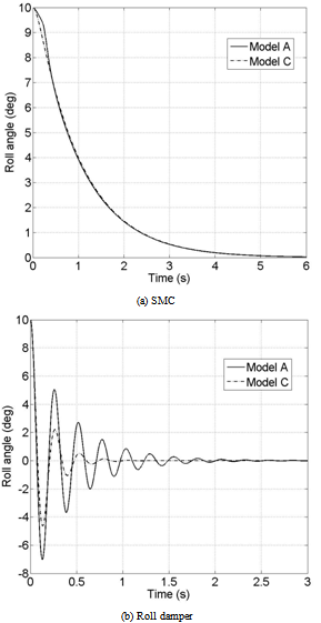 | Figure 6. Controlled roll angle; α=32.5°;∅0=1°;∅0=0°/s |
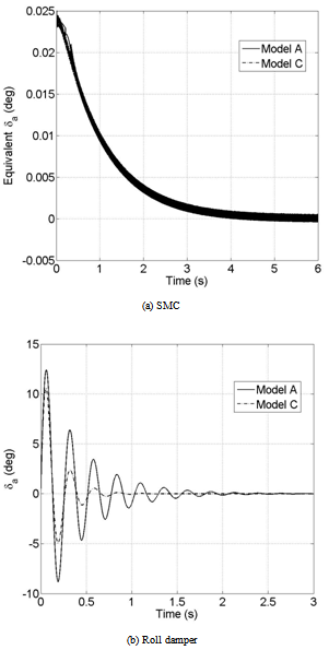 | Figure 7. Control action; α=32.5°;∅0=1°;∅0=0°/s |
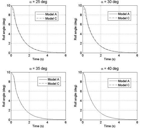 | Figure 8. SMC controlled roll angle for model A and C; ∅0=10°;∅0=0°/s |
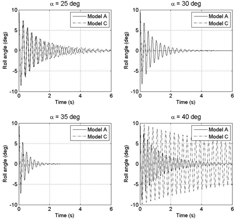 | Figure 9. Roll damper controlled roll angle for model A and C; ∅0=10°;∅0=0°/s |
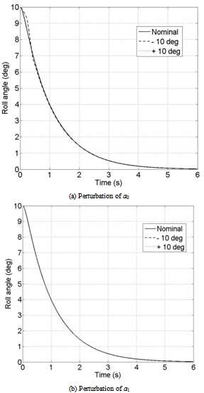 | Figure 10. SMC controlled roll angle with perturbations; α=32.5°; ∅0=10°;∅0=0°/s |
5. Robust Assessment
- One of the characteristics which makes SMC popular is its robustness to uncertainties. In the considered application this feature is important because of the difficulty in modeling accurately the wing rock motion and the response to controls. In fact, the real phenomenon is subject to the effect of aerodynamic asymmetries, couplings and wing-body vortex interactions which can hardly be modeled, even fitting experimental data. The parameters ai of Equation (3) are estimated from experimental tests. They contain a certain level of uncertainty and variability (∆∅ = ±10° ) which can alter the performance of the controller. A robust assessment of the SMC is carried out testing the controller designed on the nominal values of ai on a model where the param- eters are arbitrarily modified. In particular a0 and a1 are separately perturbed so that the steady state angular value of the limit cycle in the free motion reaches a ±10° offset from the nominal case. In Equation (3) the parameter a0 has the meaning of linear stiffness in the restoring moment a0 ∅ + a3 ∅3 and a1 represents a constant damping parameter of the overall damping coefficient a1 + a4∅2 . The same analysis is performed for the roll damper and the obtained results are compared.
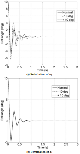 | Figure 11. Roll damper controlled roll angle with perturbations; α=32.5°; ∅0=10°;∅0=0°/s |
6. Conclusions
- In the present paper, a method to suppress wing rock through sliding mode control is proposed. Sliding mode control is chosen for its robustness with respect to model uncertainties and for its finite time convergence.Simulations, based on an experimental parametric nonlinear model, prove the method to be effective in eliminating the unwanted rolling motion in all conditions and for different model configurations.The results for SMC are compared with the behavior obtained with a conventional roll damper. Such controller is able to suppress the oscillatory motion, but with larger oscillations. Results suggest that an ad hoc optimization procedure for the roll damper should be implemented.The question of compatibility of SMC with conventional servo-actuators, normally used for vehicle steering such as ailerons, still remains. The use of impulsive or discontinuous actuators (for instance movable forebody strakes or pneumatic suction-blowing devices) may over- come these limitations.Robustness is assessed testing the controller with a simulation model altered by parametric disturbances. SMC shows excellent insensitivity to disturbances. The roll damper offers satisfying responses, but is affected by parametric changes.As a final comment, the availability of a realistic non- linear simulation model is an attractive opportunity to validate and test, at least off line, a control design methodology developed for nonlinear mechanical systems.