-
Paper Information
- Next Paper
- Paper Submission
-
Journal Information
- About This Journal
- Editorial Board
- Current Issue
- Archive
- Author Guidelines
- Contact Us
International Journal of Composite Materials
p-ISSN: 2166-479X e-ISSN: 2166-4919
2013; 3(6A): 1-9
doi:10.5923/s.cmaterials.201309.01
Multi-Phase Carbon Fiber-MWNT/Epoxy Composites
 Abstract
 Reference
 Full-Text PDF
 Full-text HTML
Antonio F. Ávila 1, Glaúcio Carley 2, Viviany Geraldo 3, Sergio de Oliveira 3
1Department of Mechanical Engineering, Universidade Federal de Minas Gerais, Belo Horizonte, 31270-901, Brazil
2Graduate Studies Program in Mechanical Engineering, Universidade Federal de Minas Gerais, Belo Horizonte, 31270-901, Brazil
3Department of Physics, Universidade Federal de Minas Gerais, Belo Horizonte, 31270-901, Brazil
Correspondence to: Antonio F. Ávila , Department of Mechanical Engineering, Universidade Federal de Minas Gerais, Belo Horizonte, 31270-901, Brazil.
| Email: |  |
Copyright © 2012 Scientific & Academic Publishing. All Rights Reserved.
The concept of multi-phase carbon fiber/nanotube was successfully introduced to high performance composites. This new laminated composite was characterized by Raman spectroscopy, X-ray diffraction, scanning electron microscopy and tensile tests. An increase on peak stress close to 85% was witnessed when the multi-phase interlayer with 206.30 mg of carbon nanotubes (CNTs) was placed into carbon fiber/epoxy laminates. The failure mechanisms are associated to CNTs distribution between and around carbon fibers. These CNTs are also responsible for crack bridging formation and the increase on peak stress. Initial stiffness is strongly affected by the CNT interlayer, however, changes on stiffness is associated to changes on nano/micro-structure due to damage. Three different behaviors can be described, i.e. for multi-phase interlayer with approximately 60 mg of CNT; the failure mode is based on cracks between and around carbon fibers, while for ones with CNT contents between 136 mg and 185 mg cracks were spotted on fibers and inside the CNT/matrix interface. The third, and final, failure mechanism is based on carbon fiber breakage, as a strong interface between CNT/matrix and carbon fibers was observed.
Keywords: Carbon nanotubes, Carbon fiber/Epoxy composites, Multi-phase composites, Raman spectroscopy
Cite this paper: Antonio F. Ávila , Glaúcio Carley , Viviany Geraldo , Sergio de Oliveira , Multi-Phase Carbon Fiber-MWNT/Epoxy Composites, International Journal of Composite Materials, Vol. 3 No. A, 2013, pp. 1-9. doi: 10.5923/s.cmaterials.201309.01.
Article Outline
1. Introduction
- In recent years, a new trend on composite materials is emerging, i.e. multi-phase composites. This is due to the increase on demand in aerospace and automotive industries due to their good characteristics of light weight, improved strength, corrosion resistance, reduced manufacturing and maintenance costs. Multi-scaled composites (MSC) are multi-phase reinforced composites, i.e. in addition to traditional reinforcement carbon fibers; the matrix is replaced by nanocomposites. As commented by Joshi and Dikshirt[1], nanocomposites can be obtained by dispersing nanoparticles/nanostructures into the polymeric matrix. According to Gouda et al[2], carbon based nano-structures, i.e. carbon nanotubes (CNT) and graphene nano sheets (GN), present remarkable mechanical, electrical and thermal properties. CNT capabilities have been observed experimentally and verified by numerical simulations. Although carbon nanotubes have great potential for applications in a large variety of usages, e.g. aerospace industry, medical and electronic devices, there is no consensus about their exact mechanical properties. As described by Saito et al[3], carbon nanotube is a honeycomb lattice rolled into a cylinder. Carbon nanotubes (CNTs) have been the center of many researches due to their dimensions and remarkable electro-mechanical properties. In general, a CNT diameter has a nanometer size and its length can be more than 1μm. Its large aspect ratio (length/diameter) is appointed as one of the reasons for the CNTs notable properties. According to Kalamkarov et al[4], single-walled nanotubes (SWNTs) have predicted specific strength around 600 times larger than steel. CNT capabilities have been observed experimentally and verified by numerical simulations. Frankland et al[5], Jin and Yuan [6] and Agrawal et al[7] are among those researchers who employed molecular dynamics for analyzing CNTs. The atomistic simulation approach was employed by Belytschko et al[8], Lurie et al[9], Gates et al[10], while thenano-mechanics modeling was described by Liu et al[11], Ruoff and Pugno[12], Li and Chou[13], Ávila et al[14]. Although CNTs have tremendous potential in a large variety of applications, e.g. aerospace and medical industries, there is no consensus about their exact mechanical properties. The experiments performed up to now have presented large variability due to the inherent complexity of manipulating these materials. However, their potential is unquestionable, in special for composites. As mentioned by Ávila et al[15], carbon based nano-structures, i.e. carbon nanotubes and graphene nano sheets (GN), can be combined to traditional composites for a multi-scale reinforcement. Moreover, the recent developments on CNT synthesis led to dramatically decreased into its cost. As a consequence, the number of researchers using carbon based nanostructures increased, and the results on nano-reinforcement of composites laminates are encouraging. Among those researchers are Kim et al[16] whom described no significant increase on tensile properties of the addition of CNTs to carbon fibers/epoxy laminates. Nonetheless, they noticed an enhancement on flexural modulus (≈12%) and strength (≈18%) with the addition of 0.3 wt. % of CNT to the epoxy system. This increase can be attributed to changes into flexural failure mechanisms. Following the same idea, Chou et al[17] discussed the influence of CNTs into the failure of laminated composites. They even proposed the concept of a multi-phase inter-laminar architecture that can bridge inter-laminar cracks. Wicks et al[18] actually produced the multi-phase nano reinforced laminated composites proposed by Chou et al[17] In their laminate, CNTs were grown in situ in all fibers leading to a “fuzzy” fibers configuration. As mentioned by Wicks, aligned CNTs bridges the plies interfaces, which can lead to an increase on toughness, for the steady state condition, 76% higher than the conventional laminated systems. Notice that for the interlayer nano reinforcement some issues must be considered, i.e. the interfacial bonds between carbon nanotubes, fiber/matrix system and the length effect into this “grip condition”. To understand the failure mechanism, Shokrieh and Rafiee[19] modeled the CNT length effect on reinforcement effectiveness. Moreover, they concluded that for carbon nanotubes with length less than 100 nm, the improvement on stiffness for CNT/polymeric systems is negligible. Experimental data provided by Ma et al[20] demonstrated the limitations of using CNTs with aspect ratio smaller than 100 into polymeric systems. The “fuzzy” fibers configuration developed by Wicks et al[18] is also limited as all plies have to be loaded with carbon nanotubes. This increase on “fiber density” due to the “CNTs loads” can lead to manufacturing limitations, e.g. a severe decrease on resin flow channels into vacuum assisted impregnation. It is clear that alternative techniques must be developed. Different techniques have being tested for incorporating CNTs into composite materials. The CNT infusion into laminated composites and its alignment by applying an electric field after the infusion was studied by Domingues et al[21]. The major criticism on Domingues’ work is the amount of CNT dispersed which is around 0.1 wt. %. Another approach tried to link CNTs to laminated composites was implemented by Wu et al[22]. Wu’s work was based on electrochemical grafting of CNTs on carbon fibers surface. Although the technique described by Wu et al[22] seems to be effective, it is limited to the CNT concentration into the solution. Moreover, as noticed by Wu, there were “preferential regions” for CNTs direct attachment to carbon fibers. These preferred sites were fibers’ grooves and edges. This phenomenon led to a non-uniform distribution of CNT on carbon fibers surface. Another technique used for attaching CNTs to carbon fibers was studied by De Riccardis et al[23] and Vilatela et al[24]. In their case, the chemical vapor deposition (CVD) technique was employed for directly grown CNTs into carbon fibers. De Riccardis’ work was based on deposition of nickel clusters and later on the CNTs were grown by hot filament chemical vapor deposition (HFCVD) technique. By using ferrocene as precursor, and CVD as the growing process, Vilatela was also able to obtain good quality CNTs. Moreover, the CVD technique employed by Vilatela and collaborators[24] seems to be much simpler and easier to control. Although the results presented by De Riccardis et al[23] and Vilatela et al[24] seem to be encouraging, much work has to be done for applications to laminated composites, in special high performance carbon fiber/epoxy systems.This paper focuses on synthesis and analysis of carbon fiber/epoxy laminated composites with the addition of an extra interlayer where CNTs were directly grown by thermal CVD.
2. Experimental Procedure
2.1. Materials
- The plain weave fiber glass used in this research has an areal density of 180 g/m2. To be able to understand the carbon nanotubes effect as interlayer into carbon/epoxy laminated composites, five different CNTs forests were grown in situ into the plain weave fiber glass. These fiber glass fabrics loaded with CNTs were placed between two layers of carbon fibers. The carbon fibers have a plain weave configuration and areal density of 200 g/m2. The epoxy system employed here is based on diglycidil ether bisphenol A (DGBA) resin and an amine hardener, i.e. AR300 and a mix of AH30/AH150 supplied by Barracuda Composites Inc. The resin/hardener ratio employed was 100:27. The fiber/epoxy system ratio is equal to 50:50. To be able to create a multi-phase/hybrid composite, a nano-phase was added to the fiber. Note that this procedure is different from the ones proposed by Ma et al[20] which dispersed CNTs into the resin and also distinct from the ones proposed by Wicks et al[18]. Instead of using a “fuzzy” configuration as described by Wicks, in this research the CNTs were grown in radial direction in a “carpet” formation. The carbon nanotubes (CNT’s) were grown directly to the fibers using a thermal chemical vapor deposition (CVD).
2.2. Synthesis and Characterization
- As discussed by Mathur et al[25], thermal CVD has high growth rate, i.e. 10µm/min, and the CNTs diameters ranges from ≈ 40-60 nm. Moreover, Raman spectroscopy indicates a good crystallinity of multiwall carbon nanotubes. In this research, a thermal CVD device from FirstNano was used for growing CNTs directly into glass fibers. CNTs can be grown over a temperature range of 600-900 C using thermal CVD. After a series of tests, the optimum temperature, considering the CNTs alignment, was selected as 750 C at an inert atmosphere (argon). The precursor used in this research was developed at UFMG’s Nanomaterials Laboratory (LN) from Physics Department. The catalyst employed was based on Iron (Fe) and Cobalt (Co) supported by Magnesium oxide (MgO). The catalyst powder was evenly distributed into the fibers’ cloth, and later on the fibers’ cloth was placed in the furnace main heating zone at 400 C for oxidation for 1 hour. The carbon source for the CVD process was ethylene (C2H2) at 300 sccm and the inert atmosphere was based on argon at 500 sccm. The CVD synthesis temperature was 750 C and each synthesis batch took around 30 minutes. The CNTs produced were mainly multiwall carbon nanotubes with average diameter of 35 nm and length ranging from 5-50μ. Once the CNTs were directly grown into the fibers, the next step is the composite manufacture. One of the most common techniques for composites’ production is the resin impregnation based on hand lay-up while the composite final consolidation is performed by cure under vacuum. The total time for cure was 24 hours, 6 under vacuum and the remaining under air. As we are dealing with multi-phase composites, it is important to characterize the nanostructures formation and location.According to Rodriguez et al[26], during the nanoparticles dispersion into polymeric matrices nano-structures are formed. The two most common detection techniques to nano-structures identification are X-ray diffraction and electron microscopy. In this research, X-ray diffraction (XRD) experiments were carried out on a Rigaku GEIGERFLEX 2037 X-ray diffract meter with Cu (λ=0.154 nm) irradiation at 40 kV and 30 mA using a Ni filter. Data were recorded in the range from 2 to 80 deg in a continuous scanning at 2 degrees per minute and sampling pitch of 0.02 deg. The high resolution scanning electron microscope (HRSEM) used was a Quanta 200 - FEG - FEI, while the transmission electron microscope (TEM) employed was a Tecnai – G2-20-FEI. As commented by Dresselhaus et al[27], Raman spectroscopy is also a powerful tool for studying carbon based nanostructures, i.e. CNTs and graphene nanosheets. In this study, the Raman spectroscopy analysis was performed using a micro-Raman NuSpec using green light (wavelength of 510 nm).The multi-phase laminated composite mechanical characterization is based on tensile tests following ASTM D 3039 standard[28]. An EMIC DL-10000 universal testing machine with 10 KN and a 500N load cells was used to perform the tensile tests at constant displacement of 0.5 mm/min. Load and displacement were continually measured by the load cell and extensometer, respectively. Furthermore, as this research focuses on understanding the CNT inter-lamina effect into laminated composites, the concept of representative volume element (RVE) described by Heinrich et al[29] was employed. Figure 1 is a schematic representation of a RVE as described by Gao et al[30]. Note that carbon nanotubes are dispersed into the resin around the carbon fibers. In our case, the multi-phase composite laminate was composed of two layers of carbon fiber/epoxy with an extra inter-layer of fiber glass fabric where CNTs were grown in situ by thermal CVD. The total average thickness was around 0.145 mm. The other dimensions followed the ASTM D 3039 standard. By applying the RVE concept, it was possible to obtain a direct relation between the CNTs effects into the composite’s macroscopic behavior.
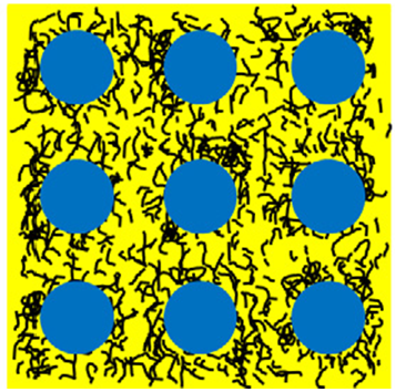 | Figure 1. RVE representation from Gao et al[30] |
3. Data Analysis
- As this research deals with multi-scale composite reinforcement, i.e. from nano to macro, two different approaches are employed. The first one is related to nano and micro structure analysis based on HSEM, Raman spectroscopy and x-ray diffraction analysis. The second one is based to tensile tests and failure mode analysis. By analyzing the two sets of data, it is possible to correlate the nano/micro structure formed and the multi-phase composite overall behavior.Figures 2A-B shows the Raman spectroscopy, while the x-ray diffraction signatures are shown in Figure 2C. As it can be observed in Figure 2A, for CNTs (the lower curve), three bands can be easily identified. The D band is around 1340 cm-1, while the G band is located around 1580 cm-1 and the G’ band is nearby 2685 cm-1. As described by Mallard et al[31], these peak values are typical from carbon based materials. Furthermore, the narrow and intense D band could be associated to the small nanotube diameter (≈ 20 nm) and the high intensity can be related to CNTs length. Moreover, the narrow G band is related to the CNT’s crystallinity, which is confirmed by the XRD signature shown in Figure 2C. By analyzing the second curve (fibers + CNTs), it is possible to observe the carbon fibers’ amorphous behavior represented by the smooth curve. However, the carbon nanotubes G band is also observed superposed to the smooth curve. The G band is indicated by the arrow and a region’s zoom is shown on Figure 2B. Finally, the last curve (upper curve on Figure 2A) indicates the fiber-glass amorphous behavior.Five different CNTs interlayers were tested. The amount of CNTs grown in each fiber glass interlayer can be described as 52.50 mg, 64.75 mg, 136.50 mg, 185.25 mg, and 206.30 mg, respectively. These CNTs contents can be translated as 1.18 wt.%, 1.32 wt.%, 2.39 wt.%, 3.28 wt.% and 3.64 wt.% with respect to the composite overall mass.
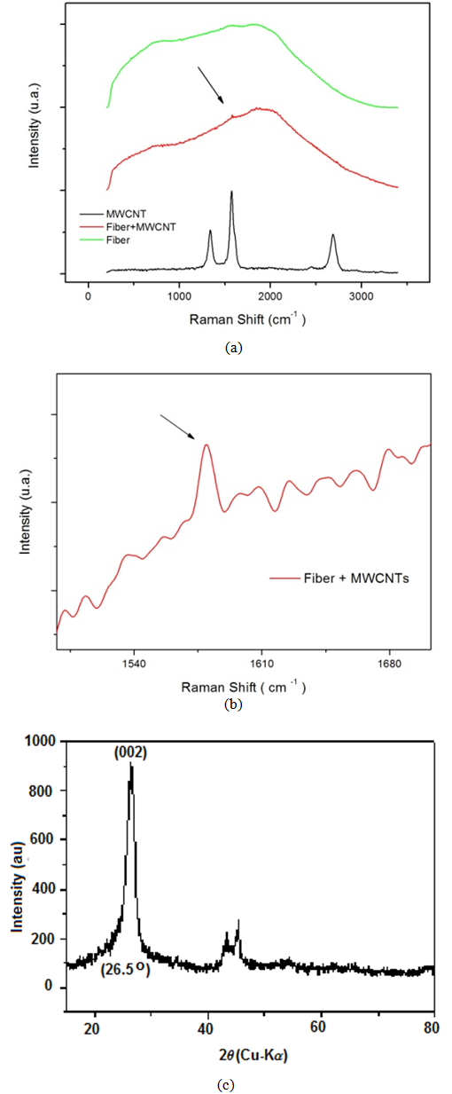 | Figure 2. Fibers and CNTs characterization. (a) Raman spectroscopy; (b) Zoom at Raman peak; (c) CNTs’ XRD signature |
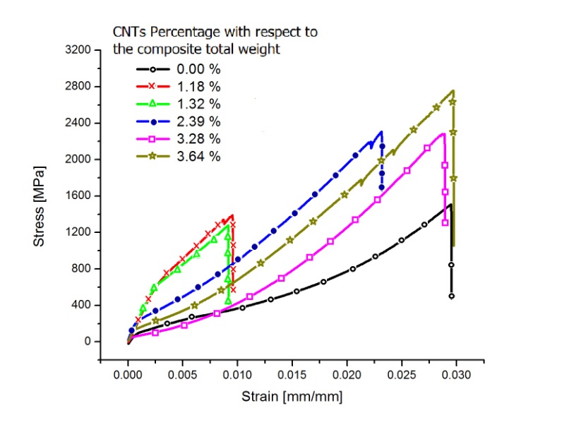 | Figure 3. Stress-strain curve |
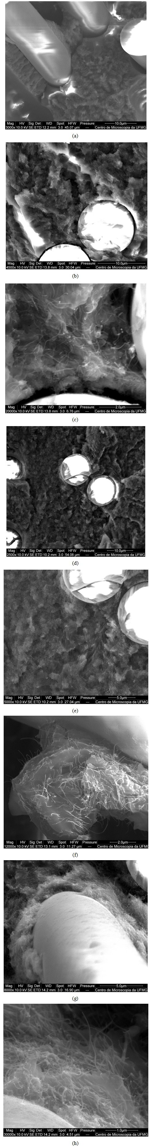 | Figure 4. SEM observations of multi-phase composite ; (a) 1.18 wt.%; (b-c) 1.32 wt.%; (d-e) 2.39 wt.%; (f) 3.28 wt.%; (g-h) 3.64 wt.% |
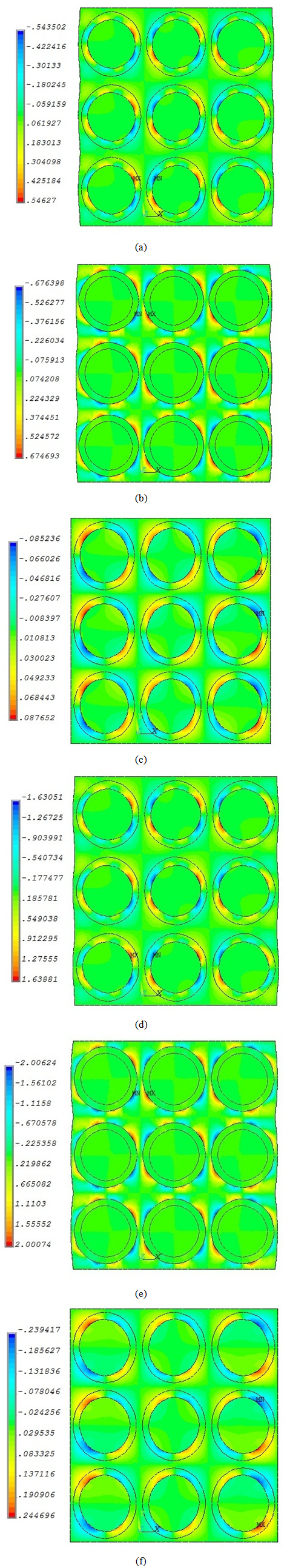 | Figure 5. Shear strain (ϒxy) fields for the following specimens: (a) No CNTs and prescribed displacement for 1.18 wt.% CNT; (b) 1.18 wt.% CNT interphase and pure resin outside; (c) 1.18 wt.% CNT and mix CNT resin at the interphase and outside; (d) No CNTs and prescribed displacement for 3.64 wt.% CNT; (e) 3.64 wt.% CNT interphase and pure resin outside; (f) 3.64 wt.% CNT and mix CNT resin at the interphase and outside |
4. Conclusions
- Carbon fibers/CNT multi-phased structures were successfully introduced to carbon fibers/epoxy laminated composites. An increase on peak stress close to 85% was witnessed when CNTs interlayer with 3.64 wt. % was placed in carbon fiber/epoxy laminates. The failure mechanisms are associated to CNTs distribution between and around carbon fibers. These CNTs are also accountable for crack bridging formation and the increase on peak stress. The initial stiffness is strongly affected by the CNT interlayer, however, changes on stiffness is related to changes on nano/micro- structure due to damage. Cracks between fibers were observed in multi-phase composites with interlayers with CNTs contents of 1.18 wt. % and 1.32 wt. %. When the nanotubes content is increased to 2.39 wt. % and 3.28 wt. %, no cracks are noted between fibers, but cracks were spotted on fibers and inside the CNT/matrix mix. Finally, when the CNT content reached 3.64 wt. %, the main failure mode was fiber breaking, as a strong bond between fiber/CNTs was observed by SEM.
ACKNOWLEDGEMENTS
- This research was supported in part by the AFOSR under contract FA9550-10-1-0050, the Brazilian Research Council (CNPq) under grants number 303447/2011-7 and 472583/ 2011-5, and the Minas Gerais State Research Foundation (FAPEMIG) grant TEC-PPM00192-12. The authors are also grateful to the UFMG’s Centre of Microscopy and Microanalysis for the technical support. The authors would like to recognize the technical support provided by the Nanomaterial’s Laboratory from the Physics department of Universidade Federal de Minas Gerais for the CNTs in situ growing into the fibers.