-
Paper Information
- Next Paper
- Paper Submission
-
Journal Information
- About This Journal
- Editorial Board
- Current Issue
- Archive
- Author Guidelines
- Contact Us
Journal of Civil Engineering Research
p-ISSN: 2163-2316 e-ISSN: 2163-2340
2012; 2(4): 12-17
doi: 10.5923/j.jce.20120204.01
Comparative Study on Behaviour of Reinforced Beam-Column Joints with Reference to Anchorage Detailing
 Abstract
 Reference
 Full-Text PDF
 Full-Text HTML
Siva Chidambaram .K .R , Thirugnanam .G .S
Dept of Civil Engineering, Institute of Road and Transport Technology, Erode-638316, India
Correspondence to: Siva Chidambaram .K .R , Dept of Civil Engineering, Institute of Road and Transport Technology, Erode-638316, India.
| Email: |  |
Copyright © 2012 Scientific & Academic Publishing. All Rights Reserved.
The ductility capacity, energy dissiaption capapcity and load – deformation behaviour of the exterior beam column joints constructed with an external anchorage system by providing a small projection beyond the column face is evaluated. The evaluation is based on the experimental results of two one fifthe scale exterior bam column joint specimens tested as part of an extensive experimental program. The control specimen (CS) constructued and detailed as per IS 13920:1993 codal provisions and externally anchoraged specimen (EAS) cast with small projecttion beyond the column face. A small axial load was applied to the column portion of the subasembly and held constant during the test. The free end of the beam was subjected to cyclic load representing a wide range from elastic to inelastic loading.By providing an external anchorage system, the reinforcement detailing and concrete placement in the joint region become eased and the behavior was better than conventional method of construction. The test results indicate that external anhorage system exhibits excellent behavior in energy dissipation , ductility and load – deformation parameter than for specimens constructed to current design recommendations.
Keywords: Exterior Beam-Column Joint,Anchorage,Ductility Factor
Article Outline
1. Introduction
- In seismic design, reinforced concrete structures must perform satisfactorily under severe load conditions. To withstand large lateral loads without severe damage, structures need strength and energy dissipation capacity. It is commonly accepted that it is uneconomical to design reinforced concrete structures for the greatest possible earthquake ground motion without damage. Therefore, the need for strength and ductility has to be weighed against economic constraints. Ductility is an essential property of structures responding inelastically during severe earthquakes. Ductility is defined as the ability of sections, members and structures to deform inelastically without excessive degradation in strength or stiffness. The most common and desirable sources of inelastic structural deformations are rotations in potential plastic hinge regions. An energy dissipation mechanism should be chosen so that the desirable displacement ductility is achieved with smallest rotation demands in the plastic hinges. Development of plastic hinges in frame columns is usually associated with very high rotation demand and may result in total structural instability (globalised failure). While for the same maximum displacement in a structural frame system, the rotation demand in the plastic hinges would be much smaller if they developed in the beams. For getting an efficient performance of beam at beam column joint we need to give proper anchorage which will provide proper dissipation of energy and ductility to the structure. Otherwise the failure may occur due to the poor anchorage at the joint by pulling out of the beam longitudinal bars from the joint.
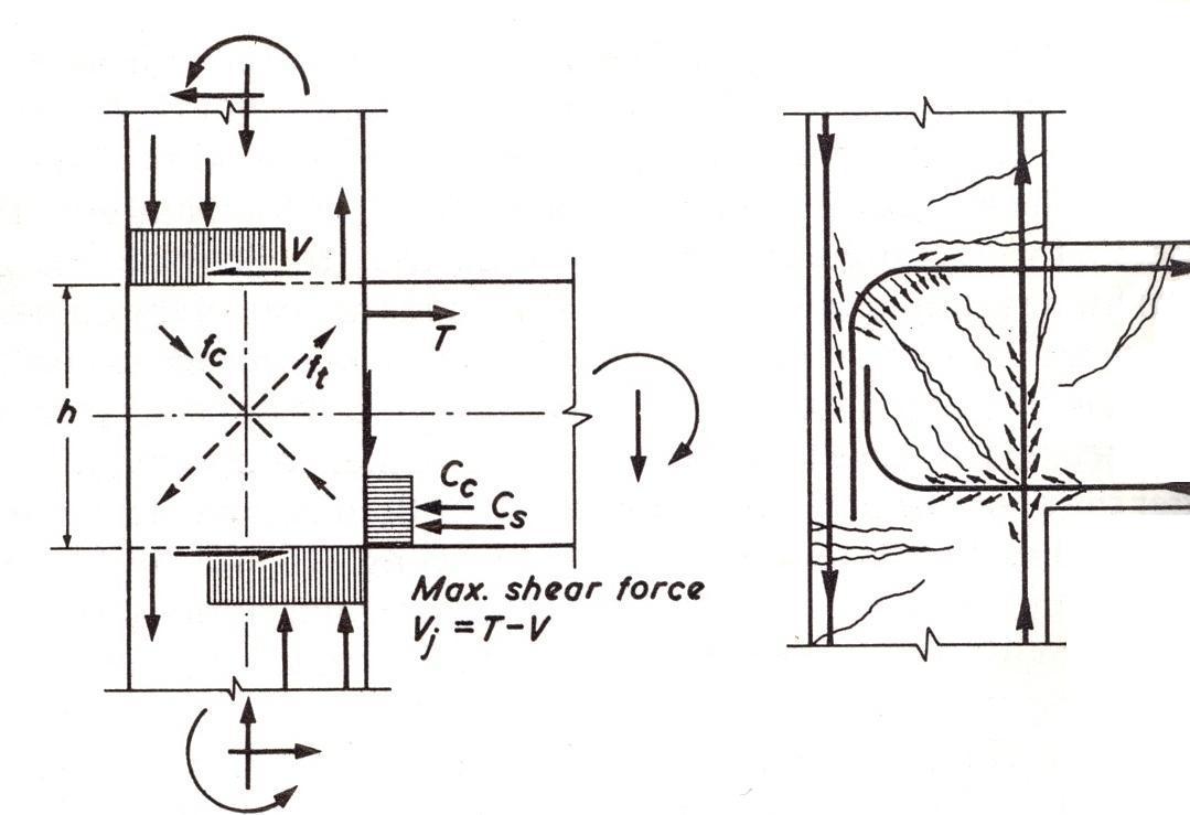 | Figure1. Force acting on the joints[12] |
2. Experimental Investigation
- The experimental study of two exterior beam-column joint namely control specimen (CS), and externally anchorage specimen (EAS). Figure 2 and 3 shows the size and reinforcements details of specimen CS and EAS. The specimens were designed for seismic load according to Indian standard[6,14].The dimension of column and beam sections are 120mm X 230mm and 170mm X 120mm, respectively. All specimens were one fifth scale of a multistorey reinforced concrete building designed under the seismic Zone – III has been analysed using STADD.pro.[16].The scaling was conducted such that the specimen had geometrical and structural indices closes to the average of the actual connection. The structure is five storey two bay frames including 1.5 m foundation depth. The maximum moment is occurred at the ground floor roof level we therefore considered that particular joint for the experimental study.
2.1. Reinforcement details
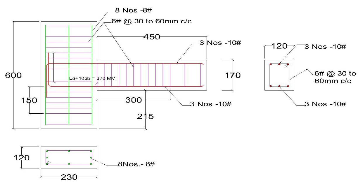 | Figure 2. Reinforcement detailing of the conventional Beam Column Joint as per IS 13920: 1993 |
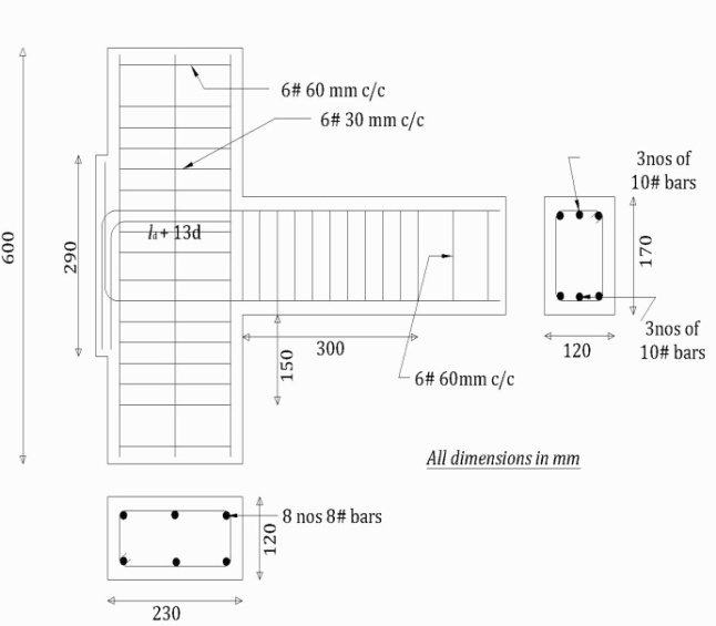 | Figure 3. Ductile Detailing of Special Anchorage Beam Column Joint |
2.2. Test setup, load history and instrumentation.
- Each beam column joint specimen was tested under cyclic loading in the predetermined load sequence. The column was centred accurately using plumb bob to avoid eccentricity. An axial load of 0.1fck strength of the column was applied on the column by means of a 50 tones hydraulic jack. Screw jacks of 20 tones capacity were used to apply the forward and reverse loading over the beam portion. Linear Variable Differential Transformer (LVDT) and dial gauges were used to measure the downward and upward displacements in the beam and fixed at a distance of 450mm clear of the column.
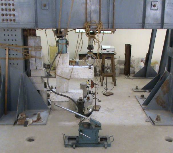 | Figure 4. a: Test Setup for Cyclic Loading for CS |
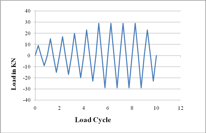 | Figure 5. Load Sequence Diagram |
2.3. Load and Deflection Measurements
- At a distance of 450mm from the column face, the load was applied at the beam through hand operated screw jack. To avoid local stress failure, bearing plate of 6mm thickness was provided at the point of loading. By changing the screw jack on either side of the beam end apply positive (downward) and negative (upward) loads. The proving ring was placed between loading point and screw jack and used to measure the applied beam forces. LVDTs are used to measure the vertical deflection of the free end of the beam under the loading point.
3. Experimental Results and Discussions
3.1. Development of Cracks
- The first crack was witnessed at the load level of 9.0kN for CS and 16.8kN for EAS. As the load level was increased, further cracks were developed in other portions of the beam in both the specimens, while the CS was reaching the ultimate load the concrete has spalled in interior side of the bottom column but there is no such failure in EAS. The crack patterns in the joint of each specimen are shown in fig 6 and 7. The joint failure modes shows the specimens failed in flexure.
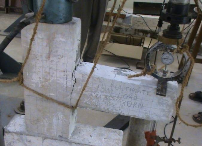 | Figure 6. Failure pattern in CS |
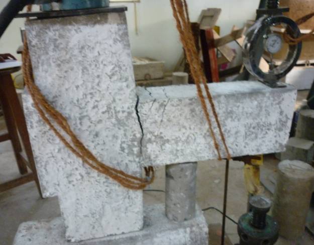 | Figure 7. Failure pattern in EAS |
|
|
3.2. Load - Deflection behaviour.
- The ultimate load carrying capacity of the Conventional RC beam-column joint and externally anchorage specimen are listed in table 1 and 2. An increase in the length of anchorage bars leads to an increase in the maximum load carrying capacity and displacement. The ultimate load carrying capacity for specimen CS is 30kN and for specimen EAS is36kN.The deflection of specimen CS is more than 12mm in the ultimate load but for specimen EAS the deflection in ultimate load is less than 9mm. The hysteresis curve for the Specimens CS and EAS has shown in figure 8 and 9.It shows the better performance of specimen EAS than the specimen CS.
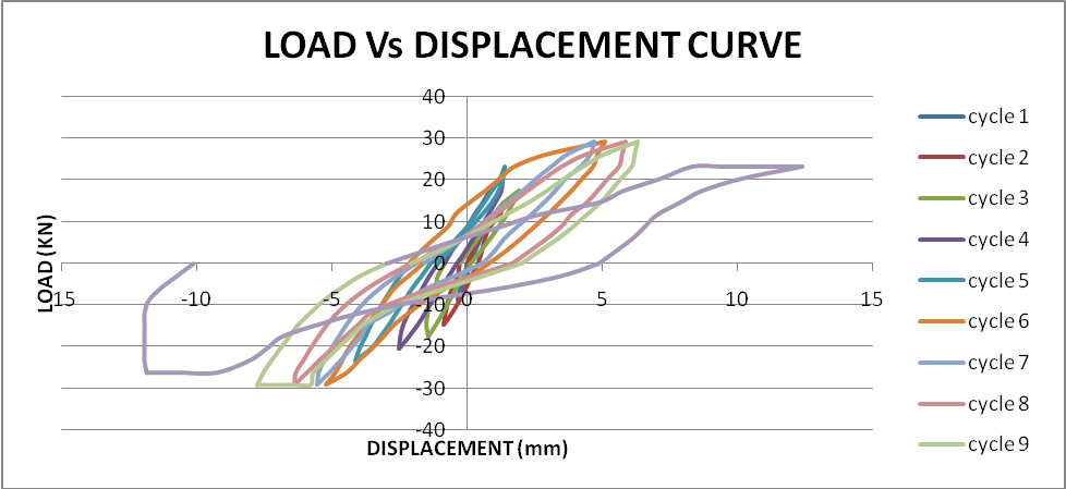 | Figure 8. Load deformation (hysteresis) curve of specimen CS |
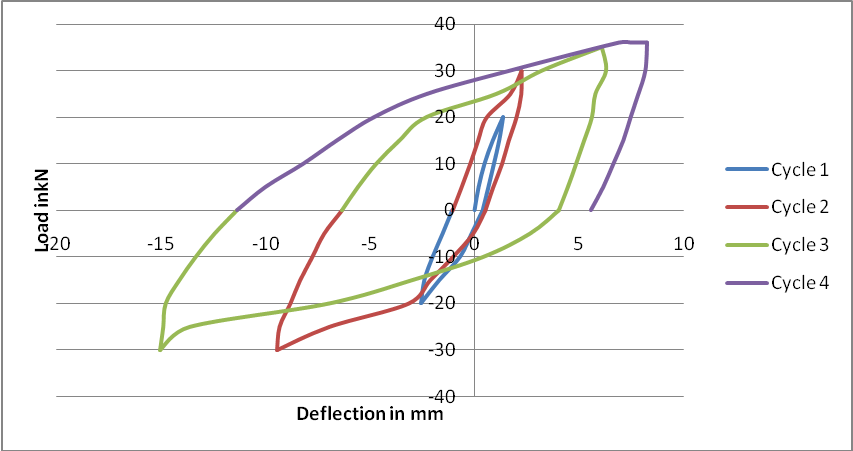 | Figure 9. Load deformation (hysteresis) curve of specimen EAS |
3.3. Relative and Cumulative Energy absorption capacity
- When the beam-column joint is subjected to reverse cyclic loading, such as those experienced during heavy wind or earthquake, some energy is absorbed in each cycle. It is equal to the work in straining or deforming the structure to the limit of deflection. The relative energy absorption capacities during various load cycles were calculated as the area under the hysteric loops from the versus load-deflection diagram and the cumulative energy absorption capacity of the beam column joint was obtained by adding the energy absorption capacity of the joint during each cycle considered and the values are presented in Tables 3 and 4
| |||||||||||||||||||||||||||||||||||||
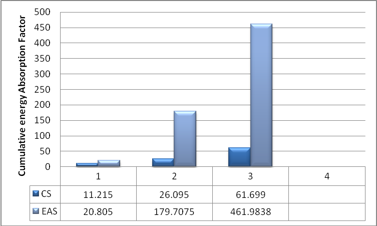 | Figure 10. Comparision of forward cycle cumulative energy absorption capacities |
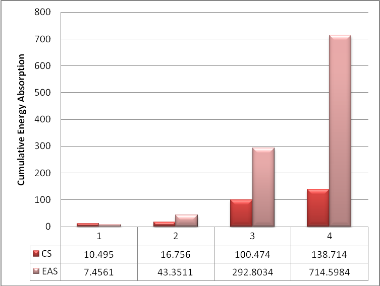 | Figure 11. Comparision of reverse cycle cumulative energy absorption capacities |
3.4. Stiffness Behaviour
- Structural stiffness controls natural period and hence seismic forces. The latter are lower for longer periods, that is, for small stiffness, but then displacements and deformations may become excessive. In addition ensuring adequate safety factors against collapse, seismic criteria should aim at controlling deformations, because they are directly responsible for damage to non-structural elements, impact with adjacent structures, panic and discomfort. Stiffness is also the main variable controlling safety against instability. Lateral displacements and internal forces produced by horizontal ground motion are amplified by interaction between gravity loads and the displacements mentioned.
| ||||||||||||||||||
|
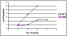
3.5. Ductility Behaviour
- It is essential that an earthquake resistant structure should be capable of deforming in a ductile manner when subjected to lateral loads in several cycles in the elastic range. Ductility of a structure is its ability to undergo deformation beyond the initial yield deformation, while still sustaining load. In this investigation ductility factor is defined as the ratio of maximum deflection obtained in each cycle to the yield deflection. The yield deflection was determined from the assumed bi-linear load deflection curve. The ductility factor µ, a measure of ductility of a structure, is defined as the ratio of ∆u and ∆y, where ∆u and ∆y are the respective lateral deflections at the end of the post elastic range and when the yield is first reached. Thus we have
 | Eq(1) |
| |||||||||||||||||||||
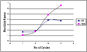 | Figure 12. Comparison of Ductility factor (Forward Cycle) |
|
 | Figure 13. Comparison of Ductility factor (Reverse Cycle) |
4. Conclusions
- 1. The first crack load of the externally anchorage Specimen is 45% more than the conventional joint specimen.2. Spindle – shaped hysteresis loops and better load carrying capacities were observed in EAS.3. EAS cumulative energy absorption capacity is about 4 times that of conventional beam column joint... 4. The beam main bar of EAS possessed better anchorage with reduced bond detoriation than CS.5. The ductility of the externally anchorage beam column joint specimen is about 2 times that of conventional beam column joint.In general it is concluded that the externally anchorage beam column joint is having superior properties than that of the conventional beam column joint and hence this type of construction may be recommended for the structures located in seismic prone areas to rectify the construction difficulty in Indian standard code detailing.
References
| [1] | ACI committee 352:1991 Recommendations for design of beam column joints in monolithic reinforced concrete structures.ACI report 352R-91. |
| [2] | A.G.Tsonos, et.al., "Seismic resistance of Type 2 Exterior Beam column joints reinforced with inclined bars" The ACI structural Journal, Title No.89-S1. 1992. |
| [3] | Andre et.al., " Seismic performance of code designed fiber reinforced concrete joints" ACI structural journal vol:91(5), pp 564-571,1994. |
| [4] | A.Murugesan et.al., "Ductile Behavior of Steel Fiber Reinforced Concrete beam-column joints subjected to Cyclic loading", National Conference on Advances and Innovations in civil Engineering, Mepco Schlenk Engineering College,Sivakasi ,pp 27-33. ,2009. |
| [5] | Bonacci J, Pantazoupoulou S ., "Parametric investigation of joint mechanics". ACI Struct JVol.90 ,no.1 ,pp.61–71,1993. |
| [6] | Gustavo j. Parra-montesinos, sean w. Peterfreund, and shih-ho chao , "Highly Damage-Tolerant Beam-Column Joints Through Use of High-performance Fiber-Reinforced Cement Composites" ACI structural journal, vol.102, no. 3, pp.487-495, 2005. |
| [7] | IS 1983(Part 1):2002 criteria for earthquake resistant design of structures. |
| [8] | IS 13920:1993 ductile detailing of reinforced concrete structures subjected to seismic forces — code of practice. |
| [9] | M. K. Thompson,et.al., “Anchorage Behavior of Headed Reinforcement: Literature Review” Technical report may 2002. |
| [10] | Murthy C.V.R, et.al., "Anchorage Details and Joint Design in Seismic RC Frames", The Indian Concrete Journal, April , pp 274 – 280,2001. |
| [11] | N. Ganesan, P.v. Indira , Ruby Abraham "Steel Fibre Reinforced High Performance Concrete Beam-Column Joints Subjected To Cyclic Loading" , ISET Journal of Earthquake Technology, vol. 44, no. 3-4, pp. 445–456, 2007. |
| [12] | Park, R and Paulay.T., "Behaviour of Reinforced Concrete Beam-Column Joints Under Cyclic Loading", Proceedings Fifth World Conference on Earthquake Engineering, Rome, Paper 88, pp.10, 1973. |
| [13] | Paulay T, Park R, Priesley MJN., "Reinforced concrete beam–column joints under seismic actions". ACI Struct J Vol.75,pp585–593,1978. |
| [14] | Paulay, T., Park, R. and Birss, G.R., "Elastic Beam-Column Joints for Ductile Frames, Proceedings 7th World Conference on Earthquake Engineering, Istanbul, Vol.6, pp.331-338,1980. |
| [15] | P. Perumal, b. Thanukumari, "Behaviour of M60 Concrete Using Fibre Cocktail In Exterior Beam-Column Joint Under Reversed Cyclic Loading" Asian Journal of Civil Engineering vol. 11, no. 2 pp 263-273, 2010. |
| [16] | Sathiskumar.S.R, et.al., "Hysteretic behaviour of lightly Reinforced Concrete exterior Beam-column joint sub-assemblages", Journal of Structural Engineering, Vol.29, No.1, pp31-36,2002. |
| [17] | Saleh H et.al.,2010, "Seismic Response of FRP-Upgraded Exterior RC Beam-Column Joints" Journal of Composites for Construction vol.14, no.195,pp 195-208, 2010. |
| [18] | STAAD Pro 2007software from Bentley . |
| [19] | Thirugnanam.G.S.,2001, "Ductile behavior of SIFCON Structural member" Journals of Structural engineering, Volume 28, No.1, pp 27-32,2001. |
| [20] | Wallace, et.al., 1998, "Use of Headed Reinforcement in Beam-Column Joints Subjected to Earthquake Loads" ACI Structural Journal,1998,Vol 95pp590-602,1998. |
| [21] | Yosio kaneko , Hiroso mihasi,Kazuki kirikoshi , "Beam Column Joints With Steel Fiber Reinforced Cementitious Composite in Steel Structures",Journal of Advanced Concrete Technology,vol.3, no.2,pp.321-330,2005. |
| [22] | Liu, cong "Seismic Behaviour of Beam-Column Joint Subassemblies Reinforced with Steel Fibres", M.E thesis, university of Canterbury ,2006 |