Ramin Tabatabaei 1, Mohammad Ershad Rahmanian 2
1Assistant Professor, Department of Civil Engineering, Islamic Azad University, Kerman Branch, Iran
2Researcher, Department of Civil Engineering, Islamic Azad University, Kerman Branch, Iran
Correspondence to: Ramin Tabatabaei , Assistant Professor, Department of Civil Engineering, Islamic Azad University, Kerman Branch, Iran.
| Email: |  |
Copyright © 2012 Scientific & Academic Publishing. All Rights Reserved.
Abstract
application of the method of the Yield Point Spectra (YPS) for seismic design and evaluation of existing structures has been studied. The important thing about the Yield Point Spectra (YPS) is that this method can be used in structural profile such as strength and hardness efficiently, so that the ductility and inter-storey drift index (IDI) of the structures were limited to the amounts of the desired performance level. This method is considered as the functional capacity spectrum method and using algorithm of linear static analysis methods in the estimation of response of structures. Also, the graphics capabilities of present methods can express authorized areas of design that satisfy multiple objectives functional. In the present method, response of multi degree of freedom (MDOF) models using the equivalent single degree of freedom (SDOF) models and Yield Point Spectra (YPS) is estimated. In numerical studies of seismic design, some steel and reinforced concrete 2-D frames in 4 and 12 floors with the Yield Point Spectra (YPS) are selected. Then, the results of the yield point Spectra (YPS) are compared with the results of the linear static analysis and nonlinear time history dynamic analysis methods and shown the present method is efficient and sufficiently accurate.
Keywords:
Yield Point Spectra (YPS), Linear Static Analysis, Nonlinear Time History Dynamic Analysis, Maximum Displacement, Required Plasticity
1. Introduction
Most researchers have based their studies on pushover analysis for estimating seismic demands of multistorey system,[1, 2]. The most procedures have lent weight to the application of inelastic analysis in seismic design and assessment[3]. Several attempts quoted of which is the capacity-spectrum approach, first proposed by Freeman et al.[4]. The procedure comprises applying a set of displacements or forces to the degrees of freedom of an idealised structural system and conducting inelastic analysis. Although some advanced pushover procedures are developed to remove the drawbacks of the conventional pushover methods, a few attempts are made to extend the application of these advanced procedures on multistorey systems[5, 6].For many years the primary objective of most earthquake structural design provisions, such as the Uniform Building Code (UBC 1997), has been to safeguard against major structural failures and loss of life[7]. Other objectives such as maintaining function, limiting damage or providing foreasy repair were not explicitly addressed in these provisions. One major development in seismic design during the last 20 years has been increased emphasis worldwide in performance based seismic design, as a result of damage and economic losses in the Loma Prieta (1989), Northridge (1994) and Hyogo-Ken Nambu (1995) earthquakes. Recent provisions require, in addition to the traditional life safety objective, to increase the expected performance of structures having a substantial public hazard due to occupancy or be used as compared to ordinary structures, and to improve the capability of essential structures to function during and after the design earthquake. The seismic performance of buildings is generally associated with structural and non-structural damage due to ground motions. For example, in the FEMA-273 documents, performance is expressed in terms of an anticipated limiting level of damage, termed a performance level, for a given intensity of ground motion[8]. The importance of drift control is revealed when it is accepted that inter-storey drift constitutes an acceptable measure of damage. Provisions such as FEMA-302/303 recognize that drift control is needed to restrict damage to partitions, shaft and stairs enclosures, glass, and other non-structural elements[9, 10].However building codes still use strength as the main parameter and have placed the computation of forces as the centerpiece of earthquake-resistant design, relegating drift calculations to the end of the design process. No realistic quantification of the nonlinear 2 displacement response of the structure during the design earthquake is done, nor of the associated structural and non-structural damage that is likely to occur. In this work a new representation of earthquake spectra is introduced, known as Yield Point Spectra (YPS). The construction of Yield Point Spectra and their application to analysis and design of SDOF systems is discussed[11]. It is shown that YPS can be used to reliably determine combinations of lateral strength and stiffness that are effective to limit drift and displacement ductility demands to arbitrary values such as those required to achieve a desired performance. Yield Point Spectra can also be used to estimate the peak displacement and the displacement ductility demands of structures responding to a given earthquake. The use of the equivalent Single Degree of Freedom (SDOF) analogy plays a central role in the procedures that are presented for using YPS in the design and approximate analysis of multistorey buildings[12].For design, YPS are used to obtain the minimum lateral strength required to limit peak roof displacement to arbitrary values for a design earthquake. Contrary to current design methods, the proposed design methodology uses an estimate of the yield displacement of the building rather than its fundamental period at the start of the design process. In numerical studies of seismic design, some steel and reinforced concrete 2-D frames in 4 and 12 floors with the Yield Point Spectra (YPS) are selected. Then, the results of the yield point Spectra (YPS) are compared with the results of the linear static analysis and nonlinear time history dynamic analysis (using the OpenSees software) methods and shown the present method is efficient and sufficiently accurate[13].
2. Relations and the Application Process of the Yield Point Spectra
The design methodology combines the use of Yield Point Spectra (YPS) with the equivalent single degree of freedom formulation, for the design of multistorey systems. The methodology is based in the following premises:1) The use of yield displacement as an alternative to period as fundamental parameter for seismic design. 2) The assumption that the nonlinear behavior of the multistorey system is completely accounted for in the SDOF responses represented in the YPS. 3) The displacement ductility of the building is assumed to be equal to the ductility of the equivalent SDOF system.An implicit assumption inherent to the equivalent SDOF technique is also made here; the deformed shape assumed to apply the equivalent SDOF formulation is a suitable representation of the displacement profile of the multistorey building responding to the design ground motion.In this section, a step by step description of the design methodology is outlined. The procedure is illustrated and validated by using some numerical examples. The steps are as follow:a) Based on the geometry of the structure, material properties, and preliminary estimates of members depth, estimate the yield displacement ( ) of the structure for a deformed profile similar to the fundamental mode of vibration. For many moment resistant steel frames a value between 0.6% to 0.9% of the height of the structure is reasonable.b) Identify the desired peak roof displacement limit of the structure (
 ). The value should be selected to limit damage to tolerable amounts and could be associated with a performance objective.c) Estimate the allowable system displacement ductility demand of the building as the ratio of the displacements obtained in steps a) and b) (
 ).d) Obtain the yield displacement of the equivalent SDOF system (
 ) using Equation (1). In this equation, the yield displacement for the building obtained in step a) is used in place of the displacement amplitude. Approximate values for the participation factor (
 ), appear to be adequate for the design of regular buildings.
 | (1) |
e) The yield displacement of the equivalent SDOF system, and the allowable system ductility are used to determine the required yield strength coefficient ( ) from the Yield Point Spectrum associated with the design ground motion. For example, enteting the YPS for the Elcentro ground motion with a yield displacement equal to 9.6 cm. and a system displacement ductility limit of 2, the minimum acceptable yield strength coefficient (
 ) is approximately to 0.3. This step is illustrated in Figure 1.
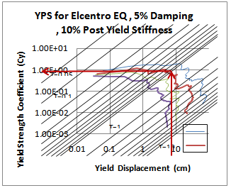 | Figure 1. Required Yield Strength Coefficient ( ) for the 4S-Steel model for the Elcentro ground motion ) for the 4S-Steel model for the Elcentro ground motion |
f) The required strength or design base shear ( ) of the MDOF system is determined using Equation (2). Approximate values for the effective modal mass coefficient (α ), appear to be adequate for the design of regular buildings.
 | (2) |
 | (3) |
g) The design base shear is vertically distributed over the height of the structure to obtain a set of lateral design forces. The base shear can be vertically distributed over the height of the structure using familiar expressions such as the ones in the Uniform Building Code (1997)[7]. The period of the equivalent SDOF can be used as an approximation to the fundamental period of the building. This period can be obtained using Equation (4). Observing that in the log-log format of the YPS, the parallel lines represent constant period; thus, the approximate SDOF period may be read directly from the YPS. | (4) |
where  is a concentrated force at the top of the building and
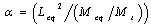
  is the fundamental period of the building.h) Members sizes and strengths should be selected following modern capacity design methods and ductile detailing provisions recommendations. Strong column-weak beam plastic hinge mechanism is suggested for good ductile behavior. In this study, an initial set of members was selected using the maximum shear forces between the three considered records that obtained in step g). Then, the selection was refined using the approximate value of period as a target to be matched by the first mode period of the frame. A difference of ±5% between the actual and the approximate periods was considered acceptable.i) Finally, peak roof displacement and peak inter-storey drift indices and total base shear are obtained by Yield Point Spectra (YPS) for steel and RC frames. Then, the results of the yield point Spectra (YPS) are compared with the results of the linear static analysis and nonlinear time history dynamic analysis methods.
 | Figure 2. Frame designed 4S-Steel |
3. Analytical Models
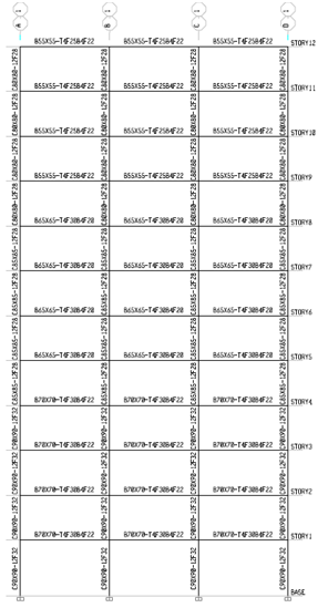
Frames examined in this study are including steel and RC frames (two 4-storey and two 12-storey). To summarize these models are named as follows (4S-Steel, 12S-Steel, 4S-Concrete and 12S-Concrete).The MDOF structures considered in this study consist of two 4-storey and two 12-storey steel and RC frames; all having three bays. The set of 4-storey frames are intended to represent low-height buildings while the set of 12-storey repre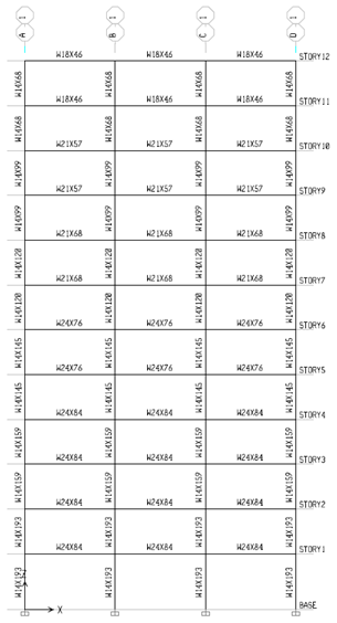 | Figure 3. Frame designed 12S-Steel |
sents medium-height buildings. All the frames were assumed to have an uniform mass distribution. The lower columns were assumed fixed at the base level for all the frames considered. An uniform storey weight of 551  was assumed for all the frames. The lowest storey height was 5
  and the remaining stories were 4
  . height; the columns were 8
  . on centre. Grade A36 steel was used for all members. Also, the compressive strength of concrete after 28 days was assumed 250
  for RC frames. Frames designed are shown in Figures 2 to 5.
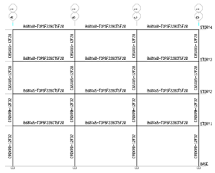 | Figure 4. Frame designed 4S-Concrete |
 | Figure 5. Frame designed 12S-Concrete |
4. Ground Motion Database
In this study, to determine the response of models and drawing up graphs of the Yield Point Spectra (YPS) used the three known ground motion that in Table 1 are shown. Also, in this study, the maximum acceleration of records scaled to  .
.| Table 1. View ground motions database |
| | No . | Record | Date | Station | Number of point | DT(sec) | Duration (sec) | PGA (g) | |
| 1 | Landers | 1992 | Lucerne | 12321 | 0.004 | 49.28 | 0.7 | | 2 | Elcentro | 1940 | Imperial Valley | 1560 | 0.02 | 31.18 | 0.32 | | 3 | Northridge | 1994 | Sylmar | 3000 | 0.02 | 59.98 | 0.6 |
|
|
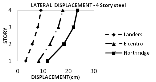 | Figure 6. Lateral displacement of nonlinear dynamic time history analysis (OpenSees) for 4S-Steel model for considered ground motion |
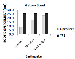 | Figure 7. Comparing peak roof displacement of YPS and OpenSees for 4S-Steel model for considered ground motion |
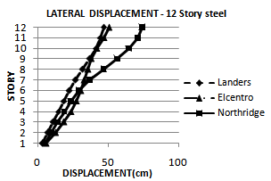 | Figure 8. Lateral displacement of nonlinear dynamic time history analysis (OpenSees) for 12S-Steel model for considered ground motion |
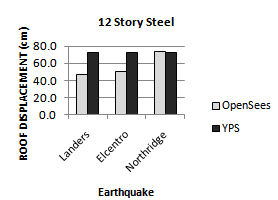 | Figure 9. Comparing peak roof displacement of YPS and OpenSees for 12S-Steel model for considered ground motion |
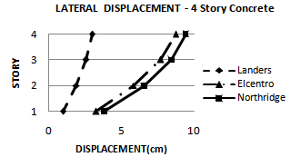 | Figure 10. Lateral displacement of nonlinear dynamic time history analysis (OpenSees) for 4S-Concrete model for considered ground motion |
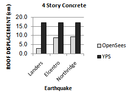 | Figure 11. Comparing peak roof displacement of YPS and OpenSees for 4S-Concrete model for considered ground motion |
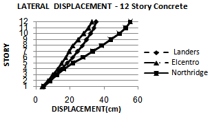 | Figure 12. Lateral displacement of nonlinear dynamic time history analysis (OpenSees) for 12S-Concrete model for considered ground motion |
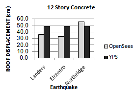 | Figure 13. Comparing peak roof displacement of YPS and OpenSees for 12S-Concrete model for considered ground motion |
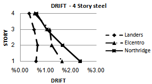 | Figure 14. Drift of nonlinear dynamic time history analysis (OpenSees) for 4S-Steel model for considered ground motion |
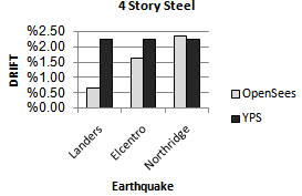 | Figure 15. Comparing drift of YPS and OpenSees for 4S-Steel model for considered ground motion |
 | Figure 16. Drift of nonlinear dynamic time history analysis (OpenSees) for 12S-Steel model for considered ground motion |
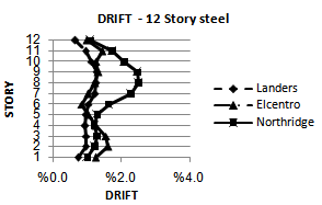
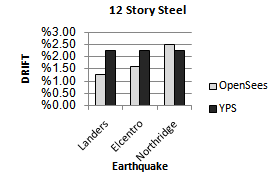 | Figure 17. Comparing drift of YPS and OpenSees for 12S-Steel model for considered ground motion |
 | Figure 18. Drift of nonlinear dynamic time history analysis (OpenSees) for 4S-Concrete model for considered ground motion |
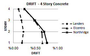
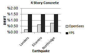 | Figure 19. Comparing drift of YPS and OpenSees for 4S-Concrete model for considered ground motion |
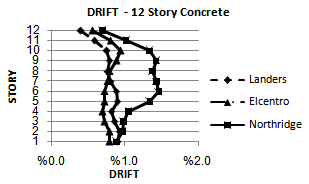 | Figure 20. Drift of nonlinear dynamic time history analysis (OpenSees) for 12S-Concrete model for considered ground motion |
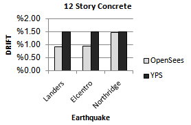 | Figure 21. Comparing drift of YPS and OpenSees for 12S-Concrete model for considered ground motion |
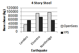 | Figure 22. Comparing base shear of YPS and OpenSees for 4S-Steel model for considered ground motion |
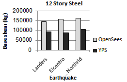 | Figure 23. Comparing base shear of YPS and OpenSees for 12S-Steel model for considered ground motion |
 | Figure 24. Comparing base shear of YPS and OpenSees for 4S-Concrete model for considered ground motion |
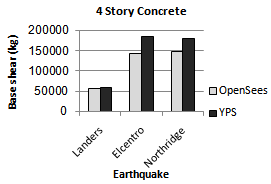
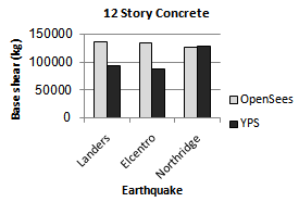 | Figure 25. Comparing base shear of YPS and OpenSees for 12S-Concrete model for considered ground motion |
5. Conclusions
From the results obtained in this study, the following was observed:Ÿ Yield Point Spectra can be used to design multistorey buildings.Ÿ The proposed design methodology is effective for controlling peak roof displacement and inter-storey drifts and in comparison with the results of nonlinear dynamic time history analysis will be acceptable and in order to ensure.Ÿ The use of the equivalent Single Degree of Freedom (SDOF) analogy plays a central role in the procedures that are presented for using YPS in the design and approximate analysis of multistorey buildings. So, base shear values obtained from nonlinear time history dynamic analysis for steel models that Their performance level has been limited to life safety are more than base shear values obtained from YPS and base shear values obtained from nonlinear time history dynamic analysis for RC models that Their performance level has been limited to continuous use are the same as the base shear values obtained from Yield Point Spectra.Ÿ The ratio of yield displacement to building height seems very stable, and may lie in the vicinity of the range (0.6%-0.9%) for many steel frames and (0.5%-0.6%) for many RC frames.The result of this study is illustrated in Figures 6 to 25.
References
| [1] | Shakeri, K., Shayanfar, M.A., Kabeyasawa, T., A story shear-based adaptive pushover for estimating seismic demands of buildings. Engineering Structures, 32(10):174-183, 2010. |
| [2] | Paraskeva, T.S. and Kappos, A.J., Further development of a multimodal pushover analysis procedure for seismic assessment of bridges. Earthquake Engineering and Structural Dynamics, 39(11):211-222, 2010. |
| [3] | Elnashai, A.S., Advanced inelastic static (pushover) analysis for earthquake applications, Structural Engineering and Mechanics, 12(1):51-69, 2001. |
| [4] | Freeman, S.A., Nicoletti, J.P. and Tyrell, J.V., Evaluation of existing buildings for seismic risk - A case study of Puget Sound Naval Shipyard Bremerton, Washington, Proc. of the United States Nat. Conf on Larthq. Eng., Berkeley, 113-22, 1975. |
| [5] | Tabatabaei, R. and Saffari, H., Energy-based Approach to Estimate Seismic Demands for Asymmetric Buildings, Journal of Earthquake and Tsunami, 4(3):215-230, 2010. |
| [6] | Tabatabaei, R., Saffari, H. and Fadaee, M.J., Application of normal flow algorithm in modal adaptive Pushover analysis, Journal of Constructional Steel Research, 65(1), 89-96, 2009. |
| [7] | Uniform Building Code, International Conference of Building Officials, Whittier California, 1997. |
| [8] | FEMA 273, NEHRP Guidelines for the Seismic Rehabilitation of Buildings, Washington, 1997. |
| [9] | FEMA 302, NEHRP Recommended Provisions for Seismic Regulations for New Buildings, Washington, 1998. |
| [10] | FEMA 303, NEHRP Recommended Provisions for Seismic Regulations for New Buildings, 1998. |
| [11] | Aschheim, M. and Black, E., Seismic Design and Evaluation of Multistory Building Using Yield Point Spectra, Mid America Earthquake Center, University of Illinois, 2000. |
| [12] | Aschheim, M., "Seismic Design Based on the Yield Displacement", Earthquake Spectra, 18(4), 581-600, 2002. |
| [13] | Mazzoni, S., McKenna, F., Scott, M. and Fenves, G., Open System for Earthquake Engineering Simulation User Command Language Manual, Pacific Engineering Earthquake Research Center, UC Berkeley, 2007. |
 Abstract
 Reference
 Full-Text PDF
 Full-Text HTML