E. V. Slivinsky , S. Yu. Radin , I. N. Gridchina
Yelets state university of I.A. Bunin
Correspondence to: E. V. Slivinsky , Yelets state university of I.A. Bunin.
| Email: |  |
Copyright © 2014 Scientific & Academic Publishing. All Rights Reserved.
Abstract
In the present article the materials concerning research of perspective construction of an independent suspension bracket of wheels of cars of supplied with the stabilizer of cross stability are provided and the reasons influencing stability of movement of the last are established. Objective of this research is development at the level of inventions of the technical solutions allowing in an automatic mode to change rotating rigidness of the stabilizer and by that to increase comfortability of transportation of passengers, and also carrying out the analytical researches, allowing to determine rational geometrical and kinematic parameters of the offered constructions of stabilizers. Results of researches are recommended to research and development and industrial structures in the field of automotive industry, as in our country, and abroad for the purpose of further study and possible implementation in practice.
Keywords:
Stabilizer, Torsion bar, Wheel, Body, Bracket, Microandmacroprofile, Banking angle, Irregularity, Annular collar, Coil spring, Cushioning
Cite this paper: E. V. Slivinsky , S. Yu. Radin , I. N. Gridchina , Upgrade of the Stabilizator of Cross Stability of the Independent Suspension Bracket of Wheels of Cars, International Journal of Traffic and Transportation Engineering, Vol. 3 No. 3, 2014, pp. 149-161. doi: 10.5923/j.ijtte.20140303.02.
1. Introduction
Successful maintenance both cargo, and cars on roads with different covering and, therefore, a broad spectrum of manifestation micro and macro roughnesses is possible only in case of high quality of a suspension bracket. Usually parameters of a suspension bracket select from calculation of admissible intensity and nature of oscillations of a body and the wheels of the car excited by roughnesses of a roadbed of [2, 6, 10]. Practice of maintenance of cars, and also numerous results of researches last show that oscillations of the cars, called micro and macro a profile of roughnesses of roads have serious impact not only on their smoothness of a course, but also on all remaining plant qualities of cars.Is known [12] that in case of maintenance, for example, the trucks which are exploiting on roads with an uneven surface, average rate of movement decreases by 40-50%, between-repairs run also decreases by 30-40%, fuel consumption increases by 50-70% and cost of transportations increases for 50-60%. It is clear that lowering of the above losses can be reached due to paving improvement of quality, and enhancement of construction of a suspension bracket of cars which plays an important role in lowering of dynamic loading of load-carrying structures of cars from influence of roughnesses of roads.It is necessary to mark also and that in case of maintenance of cars on roads of high quality their suspension brackets also should pay a close attention. In recent years enhancement of construction of suspension brackets is carried out not only from the point of view of cross stability of the car, but also from the point of view of controllability especially at high speeds of their movement. In constructions of cars and other trackless vehicles different [3, 6, 10] arrangement diagrams of suspension brackets are widely used.Suspension brackets separate on dependent and independent. At the first of one wheel in the vertical plane, arising from its meeting with roughness of the road, involves movement of the second car located on another side. In the second each of wheels has an independent communication system with vehicular part of the car and moves irrespective of other wheels. In constructions of the modern cars and in particular their front bridges independent suspension brackets found broad application.We will consider in more detail construction of a front suspension bracket of the car, shown in fig. 1a.At such construction the turning pins 1 bearing on steering wheels, by means of bolt 2 are connected to stands 3. The lower ends of stands 3 by means of the lower levers of 4 suspension brackets hinged are fixed on a cross-piece 5 frame of the car. The upper ends of stands also articulatly are connected to the tree-structured lever 6. Between the lower levers 4 and frame cross-piece 5 screw springs are set. Vertical relocation of wheels restrain springs. From the provided figure it is visible that each wheel of such suspension bracket works independently and oscillations of one aren't transferred to others. However the described suspension bracket, despite the specified advantages, has the essential shortcoming, being that by its operation there are the considerable side rolls of a body reaching such values that movement of the car becomes unsafe. Therefore in constructions of independent suspension brackets apply the device called by the stabilizer. Such independent suspension bracket with the stabilizator of cross stability is shown in fig. 1b.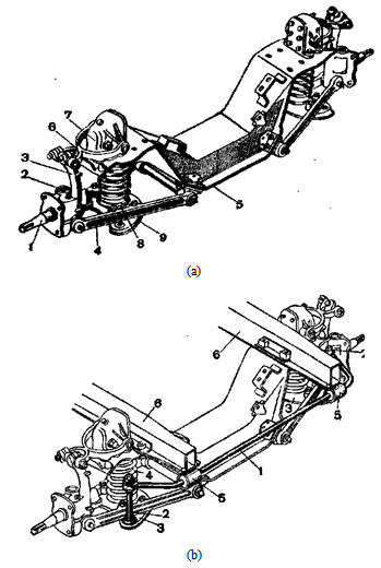 | Figure 1. Serial design of independent suspension of car |
In this case the stabilizer is executed in the form of crossly located steel elastic rod and its ends by means of stands 2 are connected to reference cups 3 bracket, on which springs lean 4. Core 1, with possibility of a twisting concerning its longitudinal axis, it is located in support 5 rigidly fixed on beams 6 auto body.Analyzing the above, and also practice of maintenance of cars, it is visible that the valid means of reduction of a cross roll is installation in suspension brackets of wheels of cars of stabilizers. At the same time, an essential constructive shortcoming last is also that they have constant rotating rigidness and can't change it automatically in the course of manifestation of a roll of a body.
2. The Purpose of the Study
Considering above-stated, in Elets State University of I.A. Bunin, NIR on the subject "Dynamics, Durability and Reliability of Transport, Construction and Road and Agricultural Machines, and also the Industrial Normal and Non-standard Equipment in relation to the Chernozem Region of the Russian Federation" is carried out and one of its sections is the scientific direction connected to development of perspective technical solutions, providing cross stability of a body of the car. The analysis of research and development reports in this area of technique, references, domestic, and foreign patents allowed to develop more effective technical solutions recognized inventions (RU2240931, RU2293663, RU2293664, RU2284924, RU2399506) and allowing in an automatic mode to realize damping of cross oscillations of bodies of cars. Therefore, the purpose of operation is carrying out analytical researches on determination of rational kinematic and geometrical parameters of such adaptive devices providing smoothness of a course of cars in case of their movement.
3. Research Methodology
Consider first a technical solution formed patent RU2240931. So in fig. 2 the stabilizer interconnected from one of suspension brackets of wheels of the car and a type of it on an arrow A with a section of part of a suspension bracket is shown.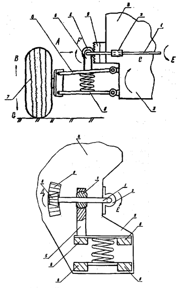 | Figure 2. General view of the stabilizer bar of car (RU2240931) |
The stabilizer consists of a rod «P» - shaped middle part which is situated in the supports 2, rigidly attached to the body 3, and end portions of the sleeves installed in the openings 4, slidably disposed in the brackets 5, rigidly fixed to the arms 6 wheel suspension 7. At the end portions of the rod 1 rigidly fixed bevel gears 8, contact with the toothed sectors 9, also rigidly attached to the body 3.Stabilizer works as follows. In the course of movement of the vehicle of its wheel 7 periodically overcome micro and macro roughnesses of roads, thus oscillations from them are transmitted through levers 6 wheel suspension 7 on the body 3. For example, if the wheel 7 moved by the arrow В, then leverage 6 relative to the axes of their attachment to the body 3 angular rotation obtained by the arrow С. Such movement is transmitted through the bracket 5 in barrel 4, and hence the end portion of the rod 1, which is bent in a vertical plane by the arrow D. This firstly results in a twisting of the middle part of the rod 1 the arrow Е and, secondly, to a twisting of the end portion of the rod 1 the arrow F due to the fact that its bevel gear 8 will roll on gear sector 9 in the direction of arrow D. Described movements cause elastic deformation of pure torsion rod 1 throughout its length, and bending the end portions in the vertical plane. Consequently, increases the damping capacity of the stabilizer through the creation of a complex stress state of all elements of the rod 1, having a "P" - shaped. When you move the wheel 7 n the opposite direction, such as arrow G, described is similar to the above process is repeated with the only difference that the elements of the stabilizer change its direction of motion, i.e. the opposite movement of the arrows С, D, Е and F.For the calculation of the basic geometrical characteristics of such stabilizer bar car, use the calculation scheme shown in fig. 3. Design scheme is a rod 1 stabilizer, one end length l provided with a bevel gear 4, interconnected with a toothed sector response 5, and another long l1, located in the transverse plane of the vehicle. The most dangerous in terms of the strength of the stabilizer bar is the point А, which is located in the center of the rod 2 stabilizer and lies on the longitudinal axis of symmetry of the vehicle. Rod stabilizer 1 loaded moment Мк, arising from the action of the circumferential force Ft in meshing gears and sectors and this power comes from the action of its own weight as the car falling on one of his wheels Gк, and dynamic component Rz, вызванной overcoming wheel roughness roadway. Portion of the stabilizer rod lengthlloaded also force F, induced transverse body roll of the car and made a circular cross section with a diameterd. Under the influence of these stresses in the rod sections 1 and 2 normal stresses arise σ shear stresses τ, at this moment diagrams Мизг and Мк will have the appearance as shown in Fig.3.By the wheel of the car (if driving) torque applied Тк and it rotates with angular velocity ωк. Wheel of the car with the help of independent suspension is related to the car body and has an angular stiffness Сβр, and stiffness Ср compression springs 3. Some numerical results are, by definition, a number of parameters that characterize the work areas 1 and 2 rod stabilizer, such as carVAZ-2107, which has the following kinematic and geometric source parameters: Gпол=1430kg, Gкуз=1278kg, L=682,5mm, lп=350mm, lo=325mm, l1=320mm, lc=230mm, l=210mm, 2Ср1=26kgs/sm, 2Ср2=30 kgs/sm, 2Сш1=2Сш2=204 kg/smиd=20mm.Calculated using the circuitry shown in figure 3 and figure 4, and the dependence presented in the paper [6], find a shoulder roll hкр car bodyVAZ-2107, Considering that the front suspension roll center lies in the plane of the road, and the rear wheel centreline. Then: h1 = 0, h2 = 320 mm, аhкр= hg- h2a/ b= 580-320∙1212/2424 = 420 mm= 42 sm.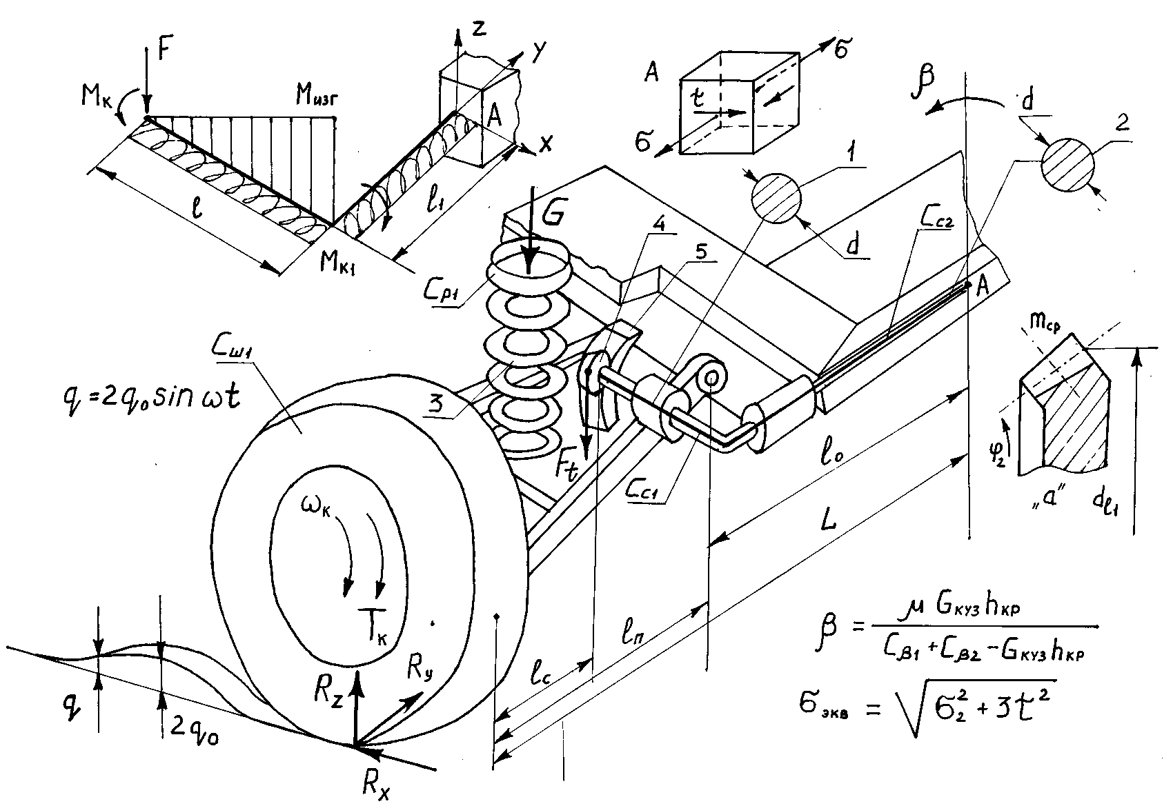 | Figure 3. The calculation scheme of promising stabilizer |
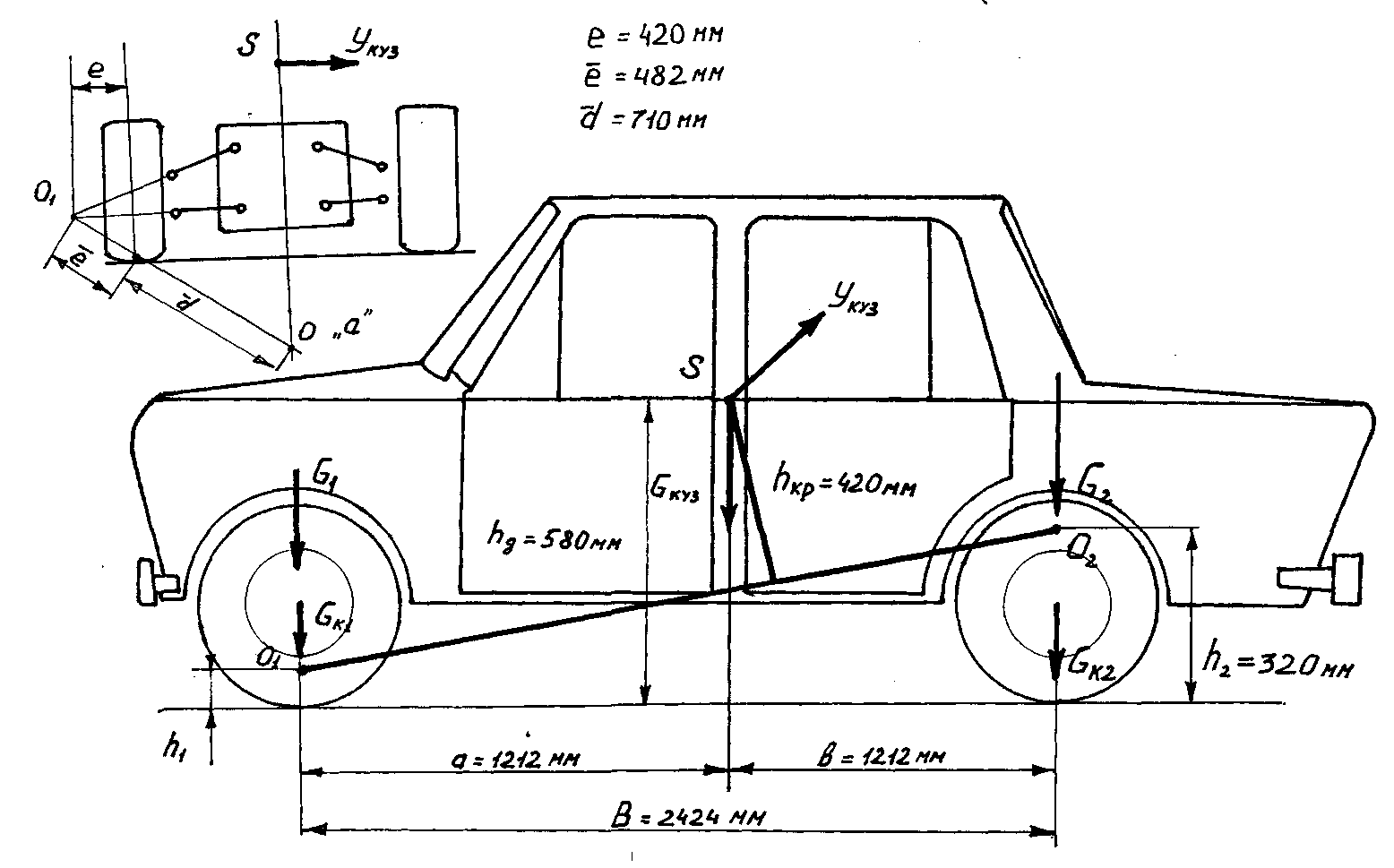 | Figure 4. The calculation scheme of force loading of structural elements of the car VAZ-2107 |
We define the angular stiffness frontСβр1and rear suspensionsСβр2in dependencies 6:Сβp1 = 2Cp1L2=26∙68,252 = 121109 kgs∙sm/radСβp2 = 2Cp2L2 = 30∙68,252 = 139741kgs∙sm/radWe also define the angular stiffness of the tire:Сβш1 = Сβш2 = 2СшL2 = 204∙68,252 = 950244kgs∙sm/radFind given angular rigidity front and rear suspensions:Сβ1 = [Cβр1 ∙Сβш1 / (Cβр1+ Сβш1)] = [121109∙950244/(121109+950244)]
  = 107418kgs∙sm/radСβ2 = [Cβр2 ∙Сβш1 / (Cβр2+ Сβш1)]
 = [139741∙950244/(139741+950244)]
 =121825kgs∙sm/radWe define the angle of heel corresponding parameters calculated from the dependence:β = [μGкузhkp/(Cβ1+Cβ2−Gкузhkp)]
 = [0.4∙1278∙42/(107418+121825−1278∙42)]
  = 21470/175567 = 0,12rad = 6°54’when, μ - specific lateral force applied at the center of gravity of the body and can be taken as 0,4 6.According to the recommendations of [6], permissible value of the transverse roll ranges from 60 – 70 at Укуз=0,4Gкуз, when Укуз – lateral force applied at the center of gravity of the car (fig.4). The resulting value β = 6°54’ quite significant value [6] and therefore to reduce the need to enter into the suspension stabilizer, and choose its preliminary angular stiffness Сс=Сβр1=107418 kgс∙sm/rad 6. Then the reduced angular stiffness front suspension will be determined depending on:Сβ1(с) = [(Cβp1+Cc)Cβш1/(Cβp1+Cc+Cβш1)]
 = [(107418+107418)∙950244/(107418+107418+950244)] = 175221kgс∙sm/radТогдаСβ(C) = Сβ1(C) + Сβ2=175221+121825
 = 297046kgс∙sm/radβ = [μGкузhkp/(Сβ1(C)+Сβ2−Gкузhkp)]
 = [0,4•1278∙42/(297046-1278∙42)]
 = 21470/243370=0,08rad = 4°58/The resulting angle of heel β = 4°58/meets the requirements of the independent suspension cars. However, when driving on roads with various micro and macro profile height 2q0 (fig. 3), this angle will vary and exceed the permissible value due to fluctuations of both the suspension and the car body, and therefore to maintain the roll angle β a permissible range of not more than 60 -70, necessary torsional rigidity of the stabilizer change automatically.Such automatic and is achieved by using the proposed design of the stabilizer (RU2240931), this is confirmed by the following example calculation.For example, if a production car VAZ-2107 stabilizer is set, which is a rod that acts as a torsional one part of it, and just bending the other part, then it is determined by the angle of twist 6:φc = 2lt[τ]/Gd=2(l1+l2)[τ]/ Gd=2∙(21+32)∙4∙103/8∙105∙2,0
 = 0,26rad ≈ 150Stabilizer having the shape shown in fig.3 (its constituent elements operate not only on torsion of one of its parts, but also to bending and torsion another), torsion angles for each of the sections l1 and l2 separately determined:φl = 2l[τ]/Gd = 2∙21∙4∙103/8∙105∙2,0 = 0,1rad = 50 7′φl1 = 2l1[τ]/Gd = 2∙32∙4∙103/8∙105∙2,0 = 0.16rad = 90 12′Given that the loading rod stabilizer, twist plot l, due to the presence of the teeth, will occur in a direction opposite to a twist portion there of l1, it can be written that, in this case its total twist angle φ’с of twist:φ’c = φl1 − φl = 0,16−0,1 = 0,06 rad = 30 42′Comparing the values of the angle of twist φс stabilizer for serial and φ’c for the proposed, it is clear that the twist angle decreases with 15° to 3042/.Analyzing the above it is clear that areas prone stabilizer complex stress state and therefore check the conditions of their strength. To do this, first define a numerical value of effort F, acting regulator of body roll, and use the scheme of two independent suspension linkage shown in Figure 3, depending on 6:F = (Cp+Cc)∙e2·
 ·β/
·β/ = 26∙422∙71∙0,1/48,22 = 140kgs,when Ср – spring suspension of one of the wheels of the car;
 β– the average value of the inclination angle when a roll stand;
 ,
,  and
and – geometric characteristics of independent suspension;
 Сс – the stiffness of the stabilizer, which will take on the same value as Ср and equal 14kgс/sm.Now we calculate the normal σl and tangential stresses τl and τl1, resulting in sections of the stabilizer rod sections using the known dependence 15-17:σl = F∙l/0,1d3 = 140∙21/0,1∙23 = 367МPа,τl = F∙(dе1/2)/0,2d3 = 140∙3/0,2∙23 = 26,3МPа,τl1 = F∙l/0,2d3 = 140∙21/0,2∙23 = 183,7МPа,when: de1-pitch diameter of the pitch circle of the gear (Fig. 3) previously assumed to be equal 60mm.To determine the equivalent stress σэкв use the fourth strength theory 16:σэкв = √σ2+3τ2 = √3672+3∙183,72
 = √134689+101273 = 485МPа.As a material for steel stabilizer accept 60С2 and we believe that the allowable stress [σэкв] will determine the yield strength σт=1177МПа 16, wondering if a safety factor of n=2.0, obtain:[σэкв] = σt/n = 1177/2.0 = 588МПа > σэкв = 485МPа.Consequently, the strength condition is satisfied.Carry out the calculation of the teeth and in particular its gear Figure 3 using the procedure provided in the source [15]. Based on the design considerations gear ratio bevel gear assign Uкп = 3,76and then define the angle φ1 sector gear pitch circle φ1 = arctg3,76= 14054’ (sector separately in Figure 3 are not shown, but it is rigidly fixed to the vehicle body) and φ2 bevel gear φ2=90−φ1= 900 – 140 54/=760 06/. Material for steel conical couples choose 40Х with σв=980МПа, hardness and heat treatment HB210 normalization. Allowable bending stress of the gear tooth is defined by the dependence15:[σ0]h = 1,5σ-1/[n]∙kσ = 1,5∙441/1,9∙1,2 = 290МPа,when, σ-1=0,45σв=0,45∙980=441МPа;
 [n] - safety factor equal 1,9 15;
 Кσ- effective stress concentration factor equal 1,2 15.We define the average module engagement mср depending on:mср = 3√2F∙(dl1/2)∙k∙γh/y1∙[σ0]h∙z1∙ψm= 3√2∙1400∙30∙1,5∙1,5/ 0,37∙290∙18∙15= 3√189000/2897 = 4,02mm. Finally accept module mср=4mm, then the pitch diameter is equal tod1=mz1=4∙18=72mm.Known [1, 7], that at present, the domestic auto industry produces a variety of large-scale production models of cars such as the VAZ-2105, VAZ-2107, VAZ-2110, VAZ-2112, etc. gross weight not exceeding 1.5 tonnes and GAZ-3102, GAZ-3110 whose gross weight does not exceed 2 tonnes. At the same time abroad also widely launched production of cars of different models with different weight characteristics corresponding to the above. All cars are subject to constant modernization associated with the improvement of the design including the increasing smoothness by using a hanging body systems, the use of advanced tire development of advanced shock absorbers, etc. Given this, as well as the ability to bind the proposed design of the stabilizer in promising models of cars and buses, developed a computer program using Delphy language to automate the process of calculating the geometric characteristics of the proposed technical solutions. As a result of these calculations, it was found that the models of cars full weight up to 1.5 tons and effort F attributable to the bevel gear on the average 156kgс and the diameter of the stabilizer bar 18mm, engaging unit must be equal m=3,5mm and pitch diameter gear d1=60mm. Car, gross weight above 1.5 tons and not exceeding 2.0 tonnes above parameters constitute F=178kgс, dс=22mm, m= 3,8mm иd1=65mm.Analyzing the above, as well as the practice of the operation of automobiles, it is clear that the real way to reduce the cross-roll is to set the wheels of cars suspension stabilizers. At the same time, the drawback considered essential constructive design of the stabilizer is that having the gear first increases and complexity of its metal structure and secondly reduces reliability under operating conditions due to the necessity of lubrication of gears and retention.Consider another solution, which is also recognized by the invention (RU2293664).Antiroll bar car (Fig. 5) consists of an elastic rod 1, in the middle part of which slots are cut 2, and it is located in the brackets 3 rigidly attached to the frame 4 car. The ends of the elastic rod 1 enshrined in the supports 5 rigidly mounted on the lower arm 6 independent suspension. In splined 2 posted spline hubs 7 movably mounted in guide 8 fixed to the frame 4 car. Splined bushing 7 arms provided with 9, which are pivotally connected rods 10 with additional levers 11 and recently rigidly secured to the lower arm 6 independent suspension, the latter using joints 12 connected with the frame 4 car and swivel 13. Fist 13 also by hinges 14 connected to the upper arm 15 Independent suspension, and the other ends thereof are pivotally coupled to the frame 4 car, между lower arms 6 independent suspension and frame 4 carinstalled compression springs 16.
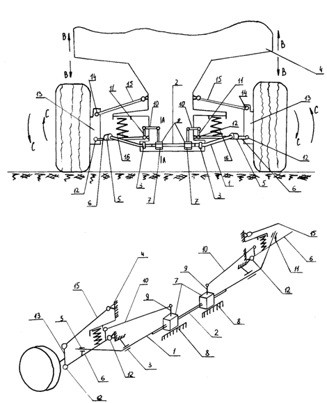 | Figure 5. Design of stabilizer for the front-wheel car (RU2293664) |
Powered stabilizer bar car follows. In the driving wheels and overcoming its micro and macro roughness get past the vertical movements, such as the arrows B, which causes angular rotations independent suspension car on the arrows C. In this case, the lower 6 and top 15 suspension arms make the angles of rotation about the hinges 12 and 14, which leads to an elastic deformation of the spring 16 and stabilizer bar 1. When such movements suspension arms through connections with poles 5 stabilizer bar 1 the lower arms 6 independent suspension, the latter provide additional angular rotation levers 11, for example, the arrow D. As additional leverage 11 rods connected 10 with levers 9, that they carry the arrows Е splined bushing 7, who move within slots 2 stabilizer bar1in their guides 8 rigidly attached to the frame 4 car. Such movement splined sleeves 7 reducing the distance between them and the brackets 3. It is known that the stiffness of a round rod is determined depending on the [16]  which shows that with decreasing length L stabilizer torsional rigidity increases. Therefore, stiffening rod 1 stabilizer creates a condition for the further restriction of the elastic angular rotation of the lower 6 and top 15 wishbone suspension, which would allow reduction roll frame 4 car and its dynamic loading. In practice, use of the vehicle wheel movement will occur differently from each other, both in direction and amplitude, but the translational motion slotted bushings 7 in all cases oscillations independent suspension will be present and automatically regulate the stiffness of the stabilizer bar 1.For the calculation of the basic geometrical characteristics of the stabilizer design scheme developed (Fig. 6) is a rod, one end of which a length l, removably secured to the sleeve on the arm front suspension wheel and the other length l1, located in the transverse plane of the vehicle and is provided with splines, interconnected with the movable sleeve, the driven rod attached to a sleeve arm. Loaded rod moment Т1кр, arising from the action of the force F applied to the wheel suspension arm. This power comes from the action of its own weight as the car falling on one of his wheels G, and dynamic component Rz, irregularities caused by overcoming wheel q0 roadway. Portion of the stabilizer rod length l loaded also forceF1, induced transverse body roll of the car and made a circular cross section with a diameter d. The other end of the rod is provided with splines diameter d1. Under the influence of these loads in any normal sections of the bar σ and shear stresses τ. By car attached wheel torque Тк and it rotates with angular velocity ωк. Wheel of the car with the help of independent suspension is due to the bodywork and has a stiffness Сш, stiffness and compression springs C1.
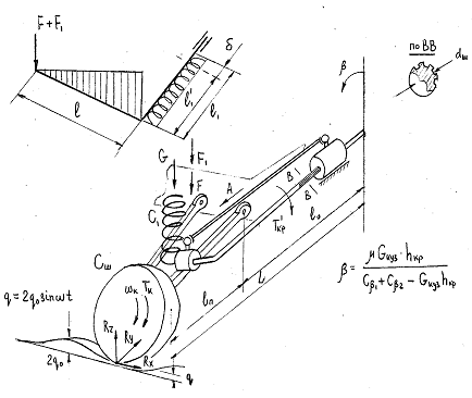 | Figure 6. The calculation scheme of stabilizer bar motion car (RU2293664) |
Above was calculated numerically by identifying a number of parameters characterizing the operation sections of the stabilizer bar for car VAZ-2107, which shows its technical characteristics. As a result, as shown by the formulas above are defined angular rigidity front and rear suspensions, respectively Сβp1 = 121109kgс∙sm/rad, Сβp2 =139741kgс∙sm/rad, and angular stiffness tires Сβш1 = Сβш2 = 950244kgс∙sm/rad. These same angular stiffness of the front and rear suspensions have accordingly made Сβ1 =107418kgс∙sm/rad and Сβ2 = 121825kgс∙sm/rad, and the angle of body roll stiffness for these turned out to be β = 0,12 rad = 6°54′In the practice of designing stabilizers considered [6, 10, 12] that the permissible value of the transverse roll ranges from 60 -70 at Укуз=0,4Gкуз, when Укуз – lateral force applied at the center of gravity of the car. The resulting value β = 6°54′ quite significant value and therefore to reduce the need to enter into the suspension stabilizer, and choose its preliminary angular stiffness Сс= Сβр1= 107418kgс∙sm/rad. Then the reduced angular stiffness front suspension and roll angle calculated from the above dependence proved to be equal to Сβ©= 297046 kgс∙sm/radиβ = 0,08 rad = 4°58′. The resulting angle of heel β = 4°58′ meets the requirements of the independent suspension cars. However, when driving on roads with various micro and macro profile height 2q0, this angle will change and probably exceed the permissible value due to fluctuations of both suspension and body of the car as a whole, and thus to maintain the roll angle β tolerance limits to no more than 60 – 70, necessary to change the torsional stiffness of the stabilizer portionl1automatically. Such a regime, and is achieved by using the proposed design of the stabilizer, it is confirmed by the following example calculation.For example, if a production car VAZ-2107 stabilizer is set, which is a rod that acts as a torsional one part and bending the other, then it is determined by the angle of twist:φc = 2lt[τ]/G∙d = 2(l1+l2)[τ]/G∙d = 2∙(21+32)∙4∙103/ 8∙105∙2,0 = 0,26rad ≈ 15°For the sitel1and serial stabilizer twist angle is determined by the formula:φl = 2l1[τ]/G∙d = 2∙32∙4∙103/8∙105∙2,0 = 0.16rad = 90 12′Assume also that for serial stabilizer after exposure bumps car wheel took a position as shown in fig. 6. Hence, the twist angle
  increase and exceed 9012´, and this will lead to an increase in the roll stand, which is quite undesirable from the viewpoint of smooth progress of the car. When you describe the phenomenon but using the proposed design of the stabilizer, Wishbone entice wheels for traction on an arrow A (Fig. 6) and move in the same direction spline hub thereby shortening the working rod stabilizerl1to
  . This will increase the torsional rigidity of the stabilizer and hence to establish the resistance and damping force of said dynamic load transmitted to the vehicle body. It can be seen from the following example. It is known that the torsional stiffness of the rod can be determined depending on the [6]:
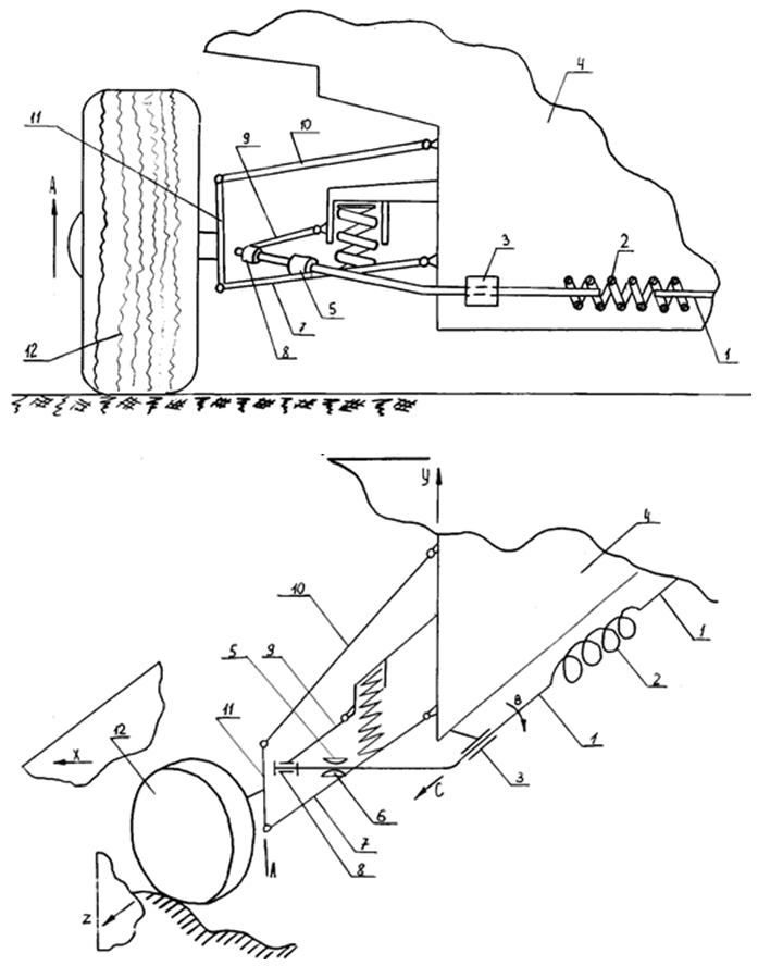 | Figure 7. Overall view of the structure of the stabilizer (RU2293663) and its position in the future |
Ж = GJρ/ld2 then for the length of the rodl1 = 320mm, torsional stiffness is equal to Ж = GJρ/l1d2 = 8·105·0,1·2,02/32,0 = 10000 kgs·sm/rad. Suppose now that the length of the rod changed to a size  = 300mm. In this case, the torsional stiffness of the rod will increase to values
  therefore, body roll will be reduced.Consider and another promising solution with regard to the structures of passenger cars, which is also recognized by the invention (RU2293663).Figure 7 shows a partial view of the overall vehicle independent suspension front view and a schematic diagram of the same part in the future. Stabilizer front suspension consists of one car and the other parts of the elastic rod 1, one end of which are linked by a coil spring 2 and arranged in brackets 3 longitudinal beams frame 4 car. The other ends of the elastic rod 1 placed in the supports 5, having a curved shape inside 6, and rigidly secured to the lower arm 7 independent suspension. At the same elastic rod ends1 bushings mounted 8, which via rods 9 pivotally connected with longitudinal beams of the frame 4 car. Lower arms 7 and upper arms 10 forming independent suspension also pivotally coupled to the frame longitudinal beams 4 and kulaks 11 bearing wheels 12.Works such stabilizer front car suspension follows. When driving his wheel independent suspension under the action of micro and macro Pothole gets moving, such as arrow А, which contributes to the angular rotation for the same direction of lower arms 7 and upper arm 10, as well as the ends of this part of the elastic rod 1 placed in the supports 5, Recently, they are bent in a vertical plane Y twisted elastic rod 1 the arrow В, and with it, and a coil spring 2 in its longitudinal plane. Simultaneously, due to the angular rotation of rods 9 in the same transverse vertical plane, Z end of the elastic rod 1 bends in the horizontal plane Х car. This phenomenon allows you to get some axial movement of the elastic rod 1 the arrow С in brackets 3 by making the inner surfaces of the supports 5 having a curved shape, as well as the elastic part of the rod 1 are interconnected by a coil spring 2, and it is elastically deformed in the same direction. Consequently, portions of an elastic rod 1, both one and the other together with coil spring 2 get complex loading associated with their bending, twisting and stretching, which allows a whole effectively dampen this type of movements and vibrations, as the suspension and the car body as a whole. The figure shows only one of the independent suspension and suspension so other can also get similar move. At the same time, and fluctuations in their movement relative to each other can have a wide range of displays, but in any case their damping will occur similarly as described above. It should be noted that the two helical springs with their end windings is screwed, for example, in the hot state onto the ends of the elastic rod 1, so that their angular movement relative to one another are excluded, they may carry out a twist only in conjunction with each other.For the synthesis of the proposed technical solutions use the design scheme (Fig. 8) allows us to study the force loading of the end portions of the torsion rod working on a bend in two planes , their tension-compression and springs located in the central part of the stabilizer loaded torque and longitudinal force. Assume that the proposed solution will be installed on a production car VAZ-2107 specifications which are presented above. Design scheme of such suspension (Fig. 8) is a rod, one end of which a length l, removably secured to the sleeve on the arm front suspension wheel and the other length l1, located in the transverse plane of the vehicle and is connected by a compression spring, a helical torsion. Loaded rod torque T, arising from the action of the force F applied to the wheel suspension arm. This power comes from the action of its own weight as the car falling on one of his wheels Gкуз, and dynamic component Rz, irregularities caused by overcoming wheel q0 roadway.
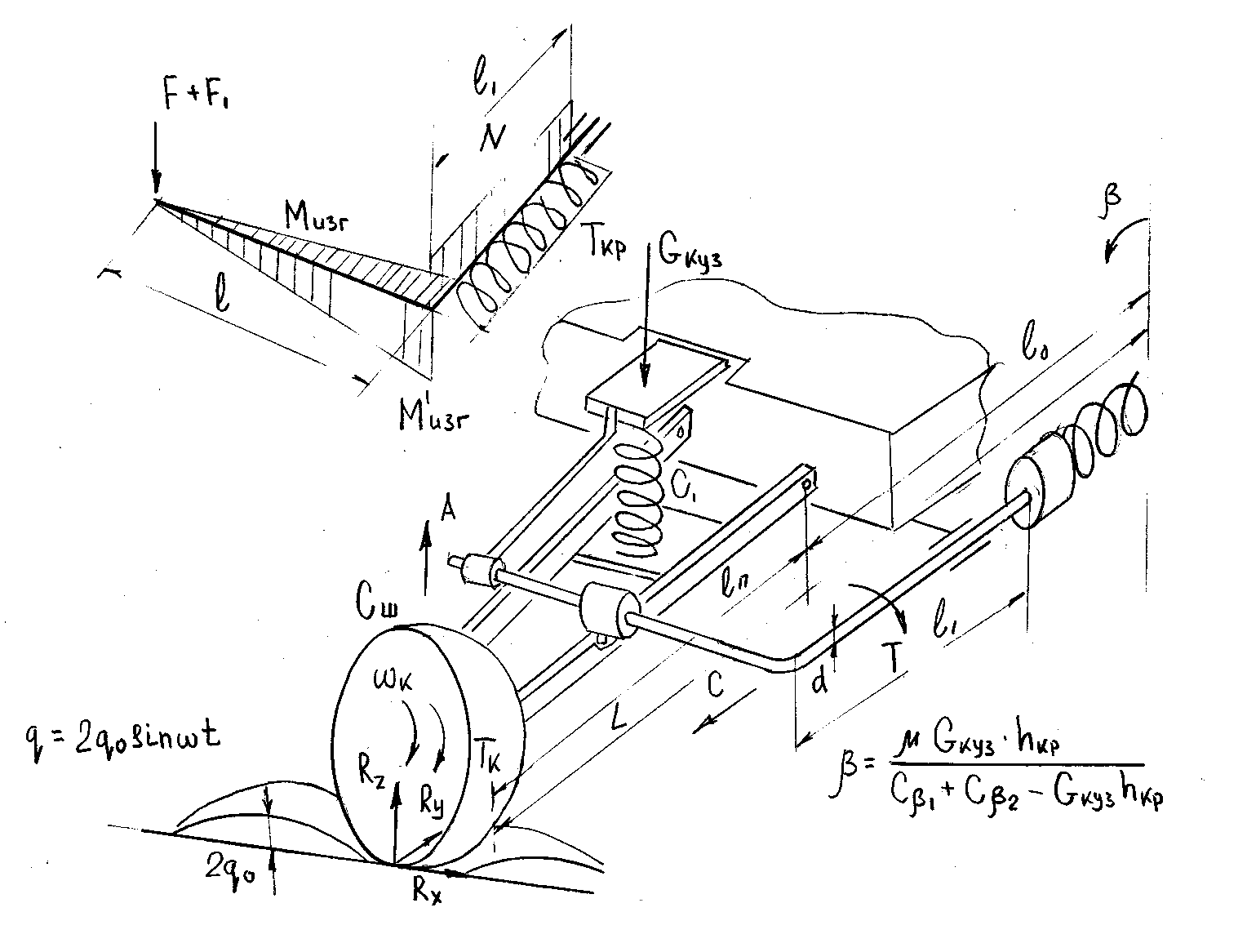 | Figure 8. The calculation scheme of stabilizer (RU2293663) |
In the scheme portion of the stabilizer rod length l loaded also force F1, induced transverse body roll of the car and made a circular cross section with a diameter d. The other end of the rod is rigidly connected to the spring compression-torsion. Under the influence of these loads in the sections of the bar in the spring compression-tension arise as normal σ, and shear stresses τ. By car attached wheel torque Тк and it rotates with angular velocity ωк. Wheel of the car with the help of independent suspension is due to the bodywork and has a stiffness Сш, stiffness and compression springs C1.Above was presented for the numerical calculation of VAZ-2107 to determine the number of parameters that characterize the work areas where the stabilizer bar its defined angular rigidity front and rear suspensions, respectively Сβp1 = 121109kgs∙sm/rad, Сβp2 =139741kgs∙sm/rad, and angular stiffness tires Сβш1 = Сβш2 = 950244kgs∙sm/rad. These same angular stiffness of the front and rear suspensions have accordingly madeСβ1 =107418kgs∙sm/rad and Сβ2 = 121825kgs∙sm/rad, and the angle of body roll for these atrocities was equal β = 0,12 rad =6°54′.As also noted that the permissible value of the transverse roll ranges from 60 – 70 at Укуз=0,4Gкуз, when Укуз – lateral force applied at the center of gravity of the car. The resulting value β = 6°54′ quite significant value and therefore to reduce the need to enter into the suspension stabilizer, and choose its preliminary angular stiffness Сс= Сβр1= 107418kgs∙sm/rad. Then the reduced angular stiffness front suspension and roll angle calculated from the corresponding dependence proved to be equal to Сβ(C)= 297046 kgs∙sm/rad and β = 0,08 rad = 4°58′.The resulting angle of heel β = 4°58′ for serial stabilizer meets the requirements of the independent suspension cars. However, when driving on roads with various micro and macro profile height 2q0, this angle will change and probably exceed the permissible value due to fluctuations of both suspension and body of the car as a whole, and thus to maintain the roll angle β tolerance limits to no more than 60-70, necessary to change the torsional stiffness of the stabilizer sections l, and l1 inautomatically. Such a regime, and is achieved by using the proposed design of the stabilizer, it is confirmed by the following example calculation.For example, if a production car VAZ-2107 stabilizer is set, which is a rod that acts as a torsional one part and bending the other, then it is determined by the angle of twist:φc = 2lt[τ]/G∙d = 2(l1+l2)[τ]/G∙d = 2∙(21+32)∙4∙103/ 8∙105∙0,2 = 0,26rad ≈ 15°For the site l1 and serial stabilizer twist angle is determined by the formula:φl = 2l1[τ]/G∙d = 2∙32∙4∙103/8∙105∙0,2 = 0.16rad = 90 12′Assume also that for serial stabilizer after exposure bumps car wheel suspension further elastically deformed and hence the angle of twist
  increase and exceed 9012´, and this will lead to an increase in the roll stand, which is quite undesirable from the viewpoint of smooth progress of the car and its controllability. When you describe the phenomenon but using the proposed design of the stabilizer, Wishbone wheels captivate for a stabilizer bar end of the arrow A (Fig. 8) and will spin in the same direction of the coil spring. Thereby increasing the torsional rigidity of the stabilizer and, consequently, to create resistance and strength damping said dynamic load transmitted to the vehicle body. It can be seen from the following example. It is known that the torsional stiffness of the rod can be determined depending on the [16]:Ж = GJρ/ld2 then for the length of the rod l1 = 320mm, torsional stiffness is equal to Ж = GJρ/l1d2 = 8·105·0,1·2.02/32·2,02 = 10000 kgs·sm/rad, and torsional stiffness of the spring is determined depending on the к= Еd4/64iD = 2·106·2,04/64·10·8,0 = 6250 kgs·sm/rad when i – the number of coils equal to 10, and D – outer diameter equal to its 80mm. (these parameters are taken constructively) Therefore the total amount of the stabilizer stiffness Ж + к = 16250 kgs·sm/radand body roll will be reduced.Given the importance of the task in terms of increasing the smoothness of cars, we have developed another promising solution with regard to the structures of passenger cars. This solution also recognized the invention (RU2284924).Figure 9 shows a portion of the stabilizer interconnected with independent wheel suspension vehicle, a view of the independent suspension of the arrow A, in its section on explosives and separate part of the stabilizer bar.
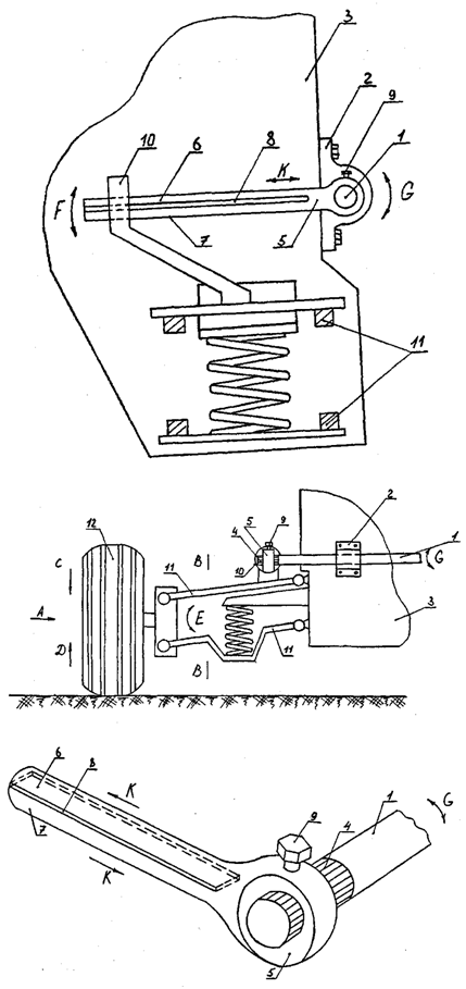 | Figure 9. General view and design details of stabilizer (RU2284924) with split console |
The stabilizer consists of a composite rod«P»-shaped middle part 1 which is situated in the supports 2 mounted on the back 3 car at its ends and slots formed 4 interconnected with counter, available at the end portions 5 composite rod «P»-shaped. The end portions 5 composite rod P-shaped and made the split between their parts 6 and 7 friction plates disposed 8, while they relatively middle portion 1 equipped with locks 9. On the other side relative to the middle portion 1 composite rod "P"-shaped end portions 5 composite rod "P"-shaped slidably mounted in the supports 10 rigidly fixed to the arms 11 arm 12 car.Stabilizer works as follows. When driving its wheels 12, interacting with the micro and macro road irregularities, oscillate the arrows C and D, wherein the levers 11 was prepared in the same angular rotation of the arrows E as they are pivotally connected to the structural elements of the wheels and bodywork 5. Such angular displacements levers 11 contribute to the rotation angles of the end sections 5 composite rod "P"-shaped due to the fact that they are installed in the supports 10, are rigidly secured to each of the levers 11 wheel suspension as well as the end portions 5 composite rod "P"-shaped middle portion attached at 1 composite rod "P"-shaped, the latter is resiliently twist about its longitudinal axis by the arrows G in creating a drag force, and the suspension thus ensuring smooth running of the car. At the same time, with rotation angle end portions 5 composite rod "P"-shaped, according to the arrow F, due to the fact that the last cut into two parts 6 and 7, there are shifted relative to each other in the longitudinal plane of the arrows K. This phenomenon is known from the strength of materials and therefore between parts 6 and 7, any force that friction and provide vibration damping body as 3 and 12 wheels. To increase the effectiveness of damping vibrations between the parts 6 and 7, end portions of the composite rod "P"-shape can be used, for example, the friction plates 5, made for example of plastics, etc., or the steel plate on that using the sputtering coated with various friction materials such as ceramics, etc.. during the movement of the vehicle described process is repeated many times.Using the above data shows the initial identification of a number of parameters that characterize the work of an independent suspension for serial car VAZ-2107, which has a twist angle of the torsion bar one part and bending the other, determined:φc = 2lt[τ]/G∙d = 2(l1+l2)[τ]/G∙d = 2∙(21+32)∙4∙103/ 8∙105∙2,0 = 0,26rad ≈ 15°Same for the proposed stabilizer, the twist angle for the cross sectionl2diameter stabilizer 20mmsolid section will equal:φ2 = 2l2[τ]/G∙d = 2∙32∙4∙103/8∙105∙2,0 = 0.16rad = 90 12′,wherein, of the other portion thereof as the length l1 made compound which contributes to the frictional forces there between, and also operates the bending, the bend can be determined depending on the:
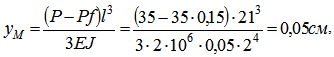 when Е – elastic modulus of the rod material 2·106 kgs/sm2;Р – dynamic component of the load applied to the suspension arms of steering wheels, 35kgs.J – axial moment of inertia 0,05d4sm4;f – coefficient of sliding friction, 0,15. If we consider the plot l1 serial rod stabilizer, which is also the rod diameter 20mmsolid section, its deflection may be determined by the formula:
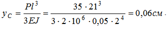 Comparing the obtained value of the deflection can be seen that the sample upgraded stabilizer (RU2284924) deflection lower than serial, hence damping dynamic loads upgraded stabilizer will occur more effectively.Consider another solution, which is also recognized by the invention (RU2399506).Figure 10 shows a general view of the stabilizer on the front of the car and the position of its stabilizer in perspective.
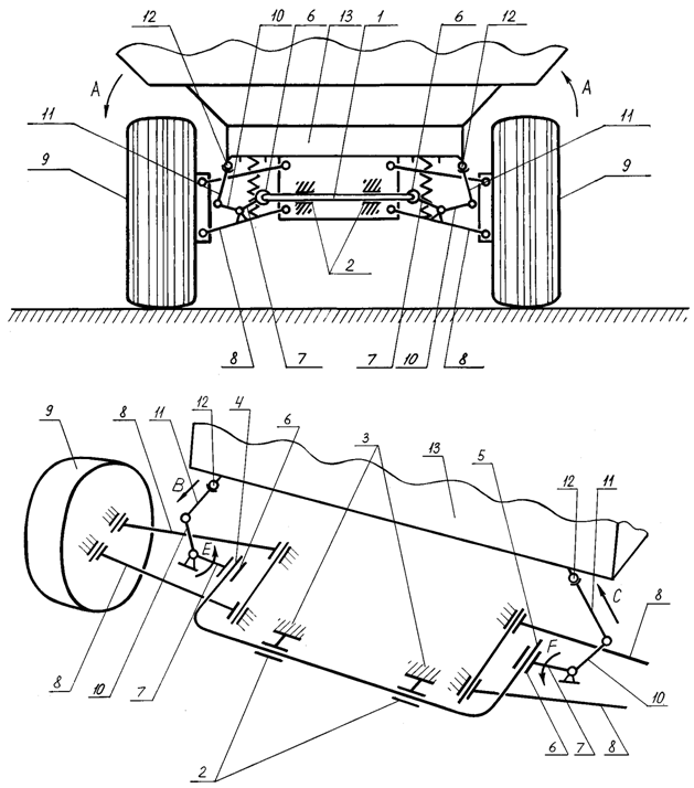 | Figure 10. An end view and a perspective of design stabilizer (RU2399506) |
The stabilizer consists of a rod 1 placed in the bracket 2 rigidly fixed to the frame of the car 3. The end portions 4 and 5, the rod 1 is located in the supports 6 are rigidly secured to the shoulders 7 of two-armed levers pivotally mounted on the suspension arms 8 of steering wheel 9. Other shoulders 10 double-arm levers using rods 11 are connected through ball joints 12 with the body 13 of the car.Stabilizer works as follows. When driving a car, because of the presence of asperities or close the roadway, his body 13 can get a bank, for example by the arrow A. This angular rotation of the body 13 to provide forward movement of the left rod 11 of the arrow B , and on the right arrow C (Fig. 10 ) and since each of the rods 11 is pivotally attached to the shoulders 10 double-arm levers their shoulders will receive 7 rotation angles , respectively, arrows E and F. as you can see the direction of the angular rotations 7 different shoulder (left shoulder 7 is rotated counterclockwise and the right clockwise), the end portions 4 and 5, the stabilizer bar 1 is bent in different directions , thereby twisting of the rod 1 on both sides thereof . And as a spin rod stabilizer 1 sided, then created a resistance force them higher than a conventional serial design. As a result, the phenomenon described here will more effectively dampen the vibrations of the car body 13 when it moves. In the case where the vehicle body 13 receives the slope in the direction opposite the above, the end portions 4 and 5 receive the stabilizer rod 1 in the opposite bending direction arrows E and F and also produce spin rod with one of its two sides in opposite directions. Future work will occur stabilizer, as described above.It was previously noted that a major part of the suspension are elastic elements which, for example, in passenger cars, and in particular their independent front suspension, spiral springs are compression. Important parameters such suspensions are their rigidity, as well as static and dynamic deflections them. It is also known [6, 12] that the increase in smoothness of cars depends essentially on reducing suspension stiffness and thereby increase its static deflection. However, if the static deflection, a number of adverse events significantly affecting the dynamics of the car and the reliability of its chassis. For example, in overcoming macro Profile roads increases the frequency of strikes in the suspension perceived limiters, changes dramatically with increasing clearance wheels vertical movements, which affects the kinematics malfunctioning steering gear under hard braking there is a significant galloping car, etc. Therefore, to eliminate such shortcomings, it is necessary to use suspension having a nonlinear characteristic. Such a problem can solve the proposed solution (RU2399506) due to the use of these characteristics, which has anti-roll bar car working under complex stress state characterized by bending and torsion clean its individual sub-sites. Consider the example of such modernization independent suspension car Volga 3112, in which the total stiffness of the springs 2СП =49kgs/sm, static deflection fП = 17,5sm, dynamic compression fД= 12,2sm and torsional stiffness of the stabilizer ККР = 210kgs/rad. Complete net weight GΣ = 1870kg, while the front axle contributes GПР = 890kg, and on the back GЗД = 980kg. Diameter rod stabilizer dC = 30mm. Define the permissible load for rod stabilizer dC = 30mmusing it in the proposed technical solution, given the nature of its power load shown in Figure 11, and considering that it is made of a material with a yield strength St60S2 material in compression σВС = 1275МPа and tensile σВР = 638МPа, with stabilizer bar dimensions of the areas respectively L = 950mmиl = 250mm.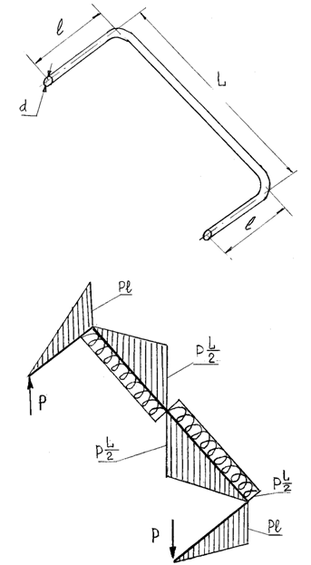 | Figure 11. The calculation scheme patent RU2399506 |
To do this, calculate the values of bending and torsional stress on the respective portions of the rod stabilizer dependencies [16]: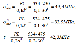 To determine the coefficient characterizing the ratio of the yield strength of the stabilizer rod material to tensile yield strength at its compression:
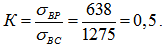 We calculate the equivalent stress σэкв, using the known dependence [16]:
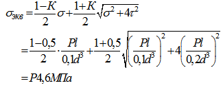 .Due to the fact that the proposed technical solution is the responsible node and a vehicle chassis connected to the driving safety, we will margin equal stabilizer rod n = 3 and then define the permissible operating load for the last depending on:
 Therefore, the load P applied to the rod stabilizer from the car body, transmitted through a two-armed lever (Fig. 10) having a ratio i = 0,2, is slightly more than 10% from GПР/2 = 445kgs, that is 46,2kgs. Consequently, on the helical compression spring suspension have not already 445kgs, and 445 – 46,2 = 398,8kgs, and this will reduce its diameter coil and thereby increase its static deflection. However, the dynamics of perceived effort portions rod stabilizer based on dynamic factor equal 1,2 [16], equals 44,5·1,2 = 53,4kgs. Therefore, finally, we will stem diameter stabilizer 32mm, which will provide the necessary performance and the proposed suspension design with the possibility of installing it on the above car.Results of the study are recommended not only AvtoVAZ but in the whole automotive industry, engineering departments and research institutes, both in our country and abroad to study the proposed technical solutions and possible further put them into practice.
4. Results of the Study
To improve the smoothness of cars and reduce body roll them occurring during road travel and overcoming macro and micro roughness of their coverage, independent suspension mounted anti-roll bars. For the selection and calculation of such devices are widely used known methods based on constructing the differential equations describing both its own and forced vibrations of cars. In actual operation of such devices has shown that they do not sufficiently meet modern requirements and therefore need a more advanced designs stabilizers. Analysis of multiple bibliographic sources, as well as domestic and foreign patents allowed to develop advanced design stabilizers, which are recognized as inventions (RU2240931, RU2293663, RU2293664, RU2284924, RU2399506). Such designs allow more efficient use of their elements, which generally undergo complex stress and work not only in torsion, but bending and torsion. For the calculation of basic geometric and strength characteristics stabilizers developed numerical schemes used and the method of their determination using the developed mathematical models to study the loading and efficiency of the proposed structures.
References
| [1] | Short automotive guides. – М.:Transportation, 1994.-220p. |
| [2] | SmirnovG.А. Theory of the motion of wheeled cars. -М.: 1990.-352 p. |
| [3] | Theory and design of the car. Tutorial for motor colleges/ V.А. Illarionov – М.:2005.- 368p. |
| [4] | Applied Mechanics. Textbook for universities.Under Ed. VM Ossietzky.М.: 1987.-488 p. |
| [5] | Shelofast V.V. Fundamentals of Machine Design. - Moscow: Publishing House of the АПМ, 2004.-472p. |
| [6] | Rotenberg R.V. Car suspension. М.: 1972.-392p. |
| [7] | IllarionovV.А. Performance Properties Car. М.: 1998.-280p. |
| [8] | KugelR.V. Durability car. М.: 1998.-432p. |
| [9] | VongG. Theory of ground vehicles. М.: 1982.-294p. |
| [10] | RotenbergR.V.Problems of development of the car's suspension. Automotive industry, №5, 1960.-24-25 p. |
| [11] | ParhilovskyI.G.On the definition of operational requirements for the smooth running of vehicles. Automotive industry, №1, 1996.-18-20p. |
| [12] | YatsenkoN.N., PrutchikovО.К. Smooth running trucks. М.:2001.-218p. |
| [13] | GoldB.V. and atc. The strength and durability of the car. М.: 1984.-397p. |
| [14] | KrainevА.Ph. Dictionary of mechanisms.М.: 1987.-560 p. |
| [15] | OrlovP.I. Design Basics: Reference - metodichekallowance. М.: 1988.-544p. |
| [16] | Feodosyev V.I. Strength of materials. М.: 1982.-425p. |
| [17] | General technical reference /Е.А. Scorohodovand atc. М.: 1990.-496p. |
| [18] | Slivinskii E.V., VasilievМ.А.Computer calculations of basic geometric and kinematic parameters of promising anti-roll cars. Science: Concepts, current state and prospects for development. Materials interuniversity scientific - practical conference. Elets 2006 y. 167 – 169p. |
 Abstract
 Reference
 Full-Text PDF
 Full-text HTML