Heejoong Kim , Hideki Sunahara , Akira Kato
Graduate School of Media Design, Keio University, Yokohama, Kanagawa, 223-8526, Japan
Correspondence to: Heejoong Kim , Graduate School of Media Design, Keio University, Yokohama, Kanagawa, 223-8526, Japan.
| Email: |  |
Copyright © 2012 Scientific & Academic Publishing. All Rights Reserved.
Abstract
Some idle spaces in the TV band, the so-called Digital Dividend have emerged through the TV channel rearrangement process as the one of the activities for DTV transition. Various wideband services including spectrum sensing application are currently being reviewed as DTV White Space application in order to cope with the wireless internet environment. However, it is hard to expect lots of DTV White Space due to geographical conditions and interference issues with broadcasters as incumbent users in the DTV band. In this paper, the authors are suggesting measures for DTV White Space usability by reviewing the availability of White Space from diverse aspects in order to improve the usage environment of DTV White Space. As a part of this study, narrowband applications have been considered for practical use of White Space from the aspect of efficient use of the DTV spectrum. Related to this, the TETRA system has been applied to this study as a narrowband application for DTV White Space. In addition, this study has suggested a direction for a DTV White Space management scheme that will be able to enhance spectrum efficiency by considering unoccupied channel conditions according to the density of DTV transmitters and relays at three DTV pilot regions in Korea, i.e. Uljin, Gangjin and Danyang. Especially, there has been a consideration of the regulatory criteria compatibility between the US and Korea in order to review the possibility of the physical expansion of DTV White Space, this study has been based on two kinds of minimum field strengths at part 73 of 47 CFR. Through computed calculations, the interoperable range of the TETRA system was reviewed according to the operating modes and power classes.
Keywords:
DTV White Space, DTV Transition, PPDR, TETRA, Spectrum Efficiency
1. Introduction
According to the increment of spectrum demand due to the advance of network and wireless technology, efficient use of spectrum is becoming more and more of a requirement. Among the areas of the radio spectrum, the portion of the spectrum of less than 1GHz, such as the terrestrial broadcast service band, is of particular interest because of the favorable coverage costs compared to those of the higher frequencies, which are currently used to provide wireless services, such as mobile internet and Wireless Fidelity (Wi-Fi). In this situation, we are faced with big challenges to develop usable channel spaces for the new services due to the DTV transition era. Regarding this, a new concept has emerged to use spatially timely unoccupied spectrum in the DTV band, which is called DTV White Space. Also, many countries including Korea are planning a DTV transition, these countries include the US and Japan. In addition, we can expect that attention to DTV White Space will also be increasing gradually.However, there are some issues for broadcasters because of incumbent users in the DTV band. In other words, broadcasters have the exclusive right to use the DTV band, and they will claim to the government and DTV White Space users that their services are being disturbed due to the mutual interference around the edge of the channel band. In addition, they have reason to be protected from government in the delivery of their services in terms of content characteristics. That is because they are providing free universal service to the public. For this reason, DTV White Space users will have a hard time protecting their service, and it will also be hard to guarantee their service quality because they have different user status as secondary users in the DTV band.In this situation, narrow band application should also be considered in order to reduce the effects on primary users due to mutual interference. Therefore, the authors have focused on TETRA (Terrestrial Truncated Radio) as a small band DTV White Space application[1]. Besides this, in term of contents characteristics, TETRA is currently used for public safety services around the DTV band, and it can be appealing to broadcasters regarding coexistence or cooperation between users. In addition, public safety has been receiving attention world-wide due to global disasters. For these reasons, TETRA systems have been selected as target systems. In this paper, the possibility of the coexistence of a TETRA system was reviewed based on the Korean DTV environment.In this paper, based on the tentative DTV channels of the pilot areas and of their neighboring areas, the unoccupied DTV channels of the areas are estimated through an iconography review. With these results, we investigated how many White Spaces could be possible according to the DTV channel conditions in the target areas. We calculated the propagation distances by applying three empirical path loss models, i.e., ITU-R P.1546 in order to derive general results for the DTV service areas under the following two electric field strength criteria: 41dBμV/m and 48dBμV/m. No-talk regions are estimated according to the above criteria in order to examine how much the secondary service area could be extended when the criterion is shifted to a new one. The rest of this paper is organized as follows. In chapter 2, the analogical interference of the idle spectrum is described through the iconography review and the results are presented. The following chapter, chapter 3, illustrates the targeted DTV White Space system and defines the related issues. Then, the interference assessment is conducted according to the interference scenario in chapter 4. We then calculate the spectrum efficiencies according to the two criteria to compare the operation margins of the secondary service. Finally, based on the results, an effective spectrum management scheme for interleave spectrums is proposed for enhancement of spectrum utilization in the DTV band in Korea.
2. Estimation of DTV Idle Spectrum
2.1. Affected Coverage in Iconography Review
Most countries are getting ready for or have already completed DTV conversion, and pilot projects for analogue TV switch-off have been carried out as a part of the DTV conversion projects[2]. Similarly, in Korea, the pilot project for the termination of analogue TV was conducted in the three areas, Uljin, Gangjin and Danyang, this project was completed at the end of 2010[3]. These areas were selected according to geographic characteristics and regional balances among the candidate regions. It can be inferred from these pilot areas that the unoccupied DTV channels depend on the local DTV conditions. Based on the tentatively assigned DTV channels in the pilot areas and the neighbouring areas, the affected areas for iconography review were classified into three cases depending on the distance of the DTV transmitters and relays from the district boundary of the target area. To simplify the iconography review, in a service area of DTV relay with 10 watts, circular areas with about 30 km diameters were considered as the distance to each district boundary as shown in Figure 1.• Case 1: The channels of DTV transmitters and relays located at the 1st and 2nd tiers.• Case 2: Case 1 + the channels of DTV transmitters located at the 3rd tier are additionally considered.• Case 3: Case 2 + the channels of DTV relays located at the 3rd tier are additionally considered.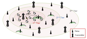 | Figure 1. Affected Coverage of Iconography Review |
According to the unoccupied channels for White Space, the first case was affected by the channels of DTV transmitters and relays within the second tier, and the first neighbor districts of the pilot test area are the second tier. The second case additionally considered to the first case by including the DTV transmitters in the secondary neighbor districts, the third tier. In addition, the last case additionally considered to the second case by including the DTV relays in the third tier.
2.2. The Results of Iconography Review
Based on the above assumption for affected coverage, it was possible to estimate the available bandwidth for each pilot area, estimation results are summarized in Table 1. In this table, around five percent or less of the 228 MHz DTV spectrum was only available as unoccupied spectrum in the third case, where the strictest criterion was applied. Even in the case of Danyang, there was no spectrum available as White Space. However, in the first and the second cases, to which the mitigated criteria are applied, the unoccupied spectrums were more than twice that of the third case. It is natural that the unoccupied spectrums decrease as the affected area increases. However, the decreasing rate of unoccupied spectrums was regionally quite different. This means that unoccupied spectrums should be determined not only by the range of the affected areas but also by the DTV conditions outside of the target area.| Table 1. Average Idle Bandwidth at the targeted Regions |
| | Region | Case | Idle BW (MHz) | Spec. vacant (%) | | Uljin(989km2) | 1 | 24 | 10.53 | | 2 | 24 | 10.53 | | 3 | 12 | 5.26 | | Danyang(780km2) | 1 | 24 | 10.53 | | 2 | 6 | 2.63 | | 3 | 0 | 0 | | Gangjin(500km2) | 1 | 54 | 23.68 | | 2 | 12 | 5.26 | | 3 | 6 | 2.63 |
|
|
3. Targeted DTV White Space System
3.1. Tendency of DTV White Space
In terms of using DTV White Space, cognitive radio (CR) is being considered as a major technology that can break through the co-interference problem between different systems. For this reason, the leading countries for White space are working on the standardization of spectrum sensing techniques based on CR technology. However, current CR technology still has potential problems caused by hidden nodes. Thus, the Federal Communications Commission (FCC), one of the concerned government agencies in the US, and the Office of Communications (Ofcom), one of the concerned government agencies in the UK, have not approved CR function-only devices. Therefore, White Space devices should be equipped with extra-functions such as Geo-location and White Space Database access in order to ensure that incumbent users will not be interrupted by White Space Devices. In other words, CR-only devices must undergo additional certifications regarding hidden node problems[4]. On the other hand, in the case of Japan, new technology like CR is planned to be reflected in DTV White Space devices after 2015 by considering the current technical limitations[5].
3.2. TETRA as DTV White Space System
In this paper, the authors considered the TETRA system as a narrowband DTV White Space application in order to estimate the possibility of coexistence with DTV users. TETRA was also designed for reliable, spectral efficient, and safe voice communications and data transmission in order to carry out PPDR (Public Protection and Disaster Relief) services. In this regard, ITU-R is classified in two ways, public protection (PP) and disaster relief (DR). For these, they were trying to find the global common spectrum for the sake of emergency communication. However, the regional frequencies according to the Radio Regulations (RR) were only distributed at the World Radio communication Conference 2003 (WRC–2003)[6]. In WRC-2003, the assigned frequency for PPDR service is shown in Table 2, in which Korea and Japan are in Region III. | Table 2. Regional Assignment Frequency (MHz) for PPDR[6] |
| | Region I(Europe & Africa) | Region II(America) | Region III(Asia & Oceania) | | 380~385, 390~395 | 746~806, 806~869, 4940~4990 | 406.1~430, 440~470, 806~824, 851~869, 4940~4990, 5850~5925 |
|
|
| Table 3. Characteristics of Operation Mode[1] |
| | Trunked Mode Operation | Direct Mode Operation | | • Basic voice and data transmission (V+D) in a circuit switched mode using the network infrastructure | • Direct mobile-to-mobile communication without the support of the network infrastructure• Mobile-to-repeater communication for communication range extension |
|
|
Regarding the technical standards of TETRA release I, it is a set of standards developed by the European Telecommunications Standards Institute (ETSI) that describe a common mobile radio communications infrastructure. In detail, the TETRA system is a digital wireless communication system using 4-slot time division multiple access (TDMA) in 25 kHz bandwidth. Each carrier provides four independent physical channels. The π/4-DQPSK modulation scheme was chosen to support a gross bit rate of 36 kbps, which means that net data rates up to 28.8 kbps can be offered to some data applications. There are two operating modes, i.e., Trunked Mode Operation (TMO) and Direct Mode Operation (DMO), in the TETRA standard[1]. TMO transmitters are fixed in location and DMO transmitters move freely in space. In order to take these characteristics into account, we have used the deterministic model and random model, respectively, in calculating interference power from TMO and DMO transmitters. The characteristics of each mode are summarized in Table 3.As such, when considering the technical and service aspects, DTV White Space could be a good alternative solution as a PPDR common band to resolve the issues of CR technology.
4. Interference Assessment
In this paper, the authors focused on the Korean DTV environment. However, DTV White Space sensing parameters in the US, i.e., -114 dBm[7], are reflected in the computing because the relevant criteria and the applications for DTV White Space are being reviewed in Korea. In addition, the US and Korea are using DTV standards made by the Advanced Television Systems Committee (ATSC).
4.1. Scenario
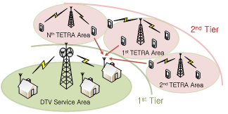 | Figure 2. Interference Scenario |
Two kinds of devices, i.e. TETRA base stations (BSs) and mobile stations (MSs) are operating at adjacent channel of DTV as interferes, and DTV receivers are in the cell boundary of the DTV station. For this, we additionally defined the two kinds of boundaries, i.e., the first and the second tier. The first tier is equivalent to the maximum allowable interference power, the second tier is available for TETRA TMO service areas decided by TETRA BSs which are located in the middle of the two tiers. In order not to compromise the reliability and functionality of the DTV system, the TETRA frequency bands for downlink communications are usually planned in this frequency range. On the other hand, TETRA MSs for DMO services are uniformly or randomly distributed over the two tiers. A scenario for analyzing the interference is shown in Figure 2.
4.2. Simulation
Based on the DTV sensing level, the protection range of the DTV service was calculated in order to estimate the affected range due to the TETRA devices. For this, we considered a DTV relay with 10 watts output power, ITU-R P.1546 was applied to calculate the DTV signal level, depending on the distance from the DTV transmitter and the relay[8]. In addition, 41 dBμV/m was used as the reference of DTV coverage that is specified in Korea, and the DTV signal ratio recommended by ATSC, i.e., the D/U ratio, was used to define the effective signal range of the DTV service, depending on the frequency used[9]. For computational convenience, the electric field strength unit (dBμV) was converted to the signal power unit (dBm) using following Equation[10].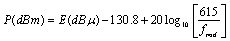 | (1) |
where fmid is the channel mid-frequency in MHz; we used 473 MHz as the mid-frequency of the first DTV channel and 695 MHz as the mid-frequency of the last DTV channel.Second, in order to estimate the DTV affected ranges due to TETRA systems, we assumed that the TETRA BSs are located at the center of the cells and that the MSs are uniformly distributed within the cell area. We also assumed that the path loss was proportional to d-γ, where d was path length and path loss exponent (γ) has a value of 3.3. The TETRA transceivers operate on an adjacent DTV channel with a 25 kHz offset that is equivalent to the channel space of the TETRA release1 system, the DTV is affected by the TETRA transceiver leakage powers, i.e., -55 dBc[1]. In addition, the average power levels from multiple interferers seen by the DTV receiver are additive. In order to consider severe interference situations, the dynamic sensitivity of the TETRA operating conditions was reflected in the simulation[11]. Total received power from the TETRA transmitters, and therefore the total receive interference is | (2) |
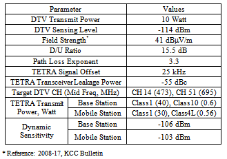
where αj is the transmit power at the jth interferer, dj is the distance between the DTV receiver and the jth TETRA device, and j is the number of the TETRA devices as interferes. According to the TETRA operation mode, i.e., TMO and DMO, interference power in Equation (2) is decomposed from deterministic values of TMO and random values of DMO. Table 4 illustrates the simulation parameters regarding the operating conditions of DTV and the TETRA devices.Table 4. Simulation Parameters
 |
| |
|
Figure 3 shows the simulation flow used to calculate the interference power induced by the TETRA devices. At first, path loss and operating power of the TETRA BSs are calculated according to the already defined parameters such as path loss exponent and operating power class of TMO and DMO. Also, the coordinates of the TETRA BSs and MSs are determined and then the aggregated interference power is calculated repeatedly until the end of target distance. After completing these computing processes, the cumulative density function (CDF) of the interference power is finally calculated. Additionally, the minimum distance between the TETRA MSs and the DTV receiver is assumed to be 10 m.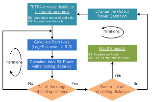 | Figure 3. Simulation Flow |
4.3. Results
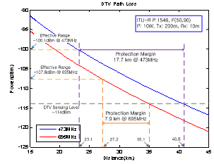
According to the above assumption, we estimated the DTV protection margin, i.e., the distance from the effective DTV signal level to the DTV sensing level, according to the movable boundaries due to the change of the first tier, as shown in Figure 2. As a result, we determined values of around 17.7 km at 473 MHz and 7.9 km at 695 MHz as spatial margin for secondary users, these values are depicted in Figure 4. Table 5 provides the computed results for the effective DTV signal range and the protection margin depending on the DTV channels and the operating power of the TETRA system.Table 5. Effective DTV Range & Margin
 |
| |
|
 | Figure 4. DTV Protection Margin |
 | Figure 5. Estimation of Impact Range of TETRA (25 kHz Offset) |
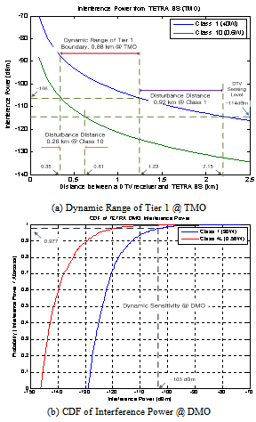
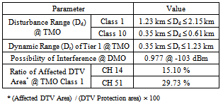
Figure 5 shows data on the estimation of impact range due to the TETRA system when operating at a 25 kHz offset from the DTV channel. In detail, Figure 5 (a) shows the results of the dynamic range of Tier 1 that was given in Figure 2. The disturbance distance due to the TETRA BS according to the transmit power class is given in Table 4.AS can be seen in Figure 5 (a), around 0.9 km or 0.3 km can be considered as the intrusive range for DTV protection due to the dynamic sensitivity of the TETRA TMO mode. Also, the radius of Tier 1, as shown in Figure 2, can be extended up to 0.9 km according to the TMO power class. Following the above results, the affected areas have been moved up to around 2.2 km toward the DTV station, and the DTV protection areas have also been shrunk due to the TETRA device operation at the edge of Tier 1. This means that the 2.2 km shrinking of the Tier 1 radius is equivalent to approximately a 30 % reduction of the total DTV protection margin, these results are depicted in Figure 6.Through the form of CDF, the interference power from the TETRA MS is shown in Figure 5 (B). As can be seen in this figure, we were able to estimate that the possibility of interference power from the TETRA MS is less than the dynamic sensitivity level in the DMO mode, the interference probability is below 3 % in all TETRA MS power classes. Table 6 summarizes the computing results of the impact ranges due to TMD and DMO.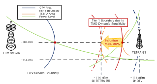 | Figure 6. Rate of Affected DTV Area @ TMO (25 kHz Offset) |
Table 6. Impact Range due to TETRA System
 |
| |
|
5. Compatibility on Regulatory Criteria
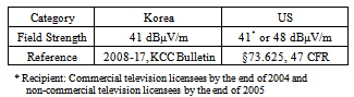
In Korea, DTV coverage in the UHF band is defined as a region in which a DTV signal of more than 41 dBμV/m can be received. Meanwhile, in the US, in which the same DTV system, ATSC, is used, there are two criteria of the electric field strength values when defining DTV coverage, these are at Pt. 73 of 47 CFR. These criteria were determined by the date of the TV license acquisition. However, the above provision will be revised at the expiration date of the license, which was acquired at the end of 2005. Table 7 shows the criteria of DTV coverage in the UHF band in Korea and in the US, which is defined by the field strength, E (dBμV/m).Table 7. DTV Coverage at UHF Band
 |
| |
|
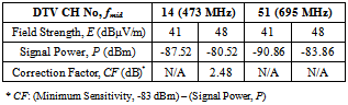
Based on the criteria of DTV coverage in the regulations, it was possible to determine the propagation distances using the empirical path loss models ITU-R P.1546, Okumura-Hata, and ETRI[8, 12]. For this, three types of path loss models were applied to calculate the propagation distances in order to obtain more objective results. In this regard, the FCC has announced -114 dBm as the criteria of the empty spaces for White Space[7]. Through Equation (1), these values can be converted to the power, P (dBm), as a function of frequency in order to carry out the prediction of the DTV path loss[13]. These calculation results are shown in Table 8. With these results, we calculated the maximum DTV propagation distances in order to derive the no-talk region based on the guidelines of minimum sensitivity, -83 dBm, and the D/U ratio at the co-channel, 15.5 dB[9].Table 8. Minimum Signal Level Calculation
 |
| |
|
Based on Table 8 and the empty space criteria of the FCC, it was possible to derive the margin of the no-talk region, Gnt (dB), according E and fmid using the following equation, these results are shown in Table 9. | (3) |
| Table 9. No-Talk Region Margins |
| | DTV CH No, fmid | 14 (473MHz) | 51 (695MHz) | | Field Strength, E (dBμV/m) | 41 | 48 | 41 | 48 | | Gnt (dB) | 10.98 | 15.5 | 7.64 | 14.64 |
|
|
where, CF (dB), the correction factor of the minimum sensitivity, was applied when the signal power has higher values than the minimum sensitivity, -83 dBm, because no-talk regions were reflected on the undesired signal levels at the same channel, and the affected regions will be reduced when the signal power is lower than the minimum sensitivity. Therefore, based on the same margin of the no-talk region between the two criteria of the DTV coverage, about 4.52 to 7 dB depending on fmid, can be expected for the new criterion, 48 dBμV/m, as additional margins when compared with 41 dBμV/m.Using the values of P (dB) and Gnt (dB), the DTV service region and the no-talk region can be calculated through the empirical propagation path loss models depending on the two kinds of electric field strength criteria, 41 dBμV/m and 48 dBμV/m, as Figure 7 shows.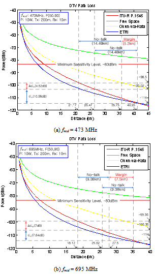 | Figure 7. Distance of No-talk Regions and Margin (ITU-R P. 1546) |
Regarding this, we considered DTV relays with 10W output power, which is the normal condition in Korea. In addition, the propagation curves for predicting field strength at 50 % of the locations 90 % of the time, F (50,90), were used to satisfy the FCC rules, §73.625, by using propagation curves from ITU-R P.1546-4 and the formula F (50, 90) = F (50, 50) –[F (50, 10) – F (50, 50)][11]. In Figure 7, it can be seen that values of 473 MHz and 695 MHz were used as fmid. Based on the results of the ITU-R models, a width of 14.48 km could be expected as the no-talk region at 41 dBμV/m. In addition, a 5.2 km wide area could also be expected as an extra operational margin when the criteria of the DTV coverage shifts to 48 dBμV/m at 473 MHz. Similarly, 9.8 km as a no-talk region and 7.5 km as a margin could be expected at 695 MHz.To derive the nominal values of the distances of the no-talk region and the margin, we calculated the values using ETRI and Okumura-Hata. The calculation results are summarized in Table 10.| Table 10. Distance of No-Talk Region and Margin |
| | Path Loss Model | ITU-R P.1546 | ETRI | Okumura Hata | | No-Talkin width | 473MHz | 14.48 km | 18.75km | 25.4 km | | 695MHz | 9.38 km | 11.82km | 16.39 km | | Margin in width @ 41 dBμV/m | 473MHz | 5.2 km | 5.14km | 9.01 km | | 695MHz | 7.5 km | 7.19km | 12.55 km |
|
|
Based on the calculating of the results, the ITU-R P.1546 and ETRI models have been chosen in order to derive the nominal values for the distance of the no-talk regions and the margin, because the ITU model has been used for DTV prediction world-wide. In particular, the ETRI model only focused on the DTV propagation condition to reflect the Korean environment. On the other hand, the results of the Okumura-Hata method are quite different compared to the others. Therefore, according to target frequencies, we can expect values of around 5.2 km to 7.5 km as the extensible ranges for secondary service operation when we shift the criteria of DTV coverage.
6. Spectrum Efficiency Improvement
As was mentioned in Chapter 4, the TETRA system has been considered as a secondary user in the DTV band. In addition, based on the results shown in Tables 9 and 10 in Chapter 5, the target areas of the TETRA trunked mode operation (TMO) services were considered for the secondary neighbor districts such as the third tier, as shown in Figure 1. Thus, it can be assumed from the service area of the DTV relay by -98.5 dBm, shown in Figure 7 (a), that the levels could be induced by the level of DTV sensitivity, -83 dB, and the D/U ratio, 15.5 dB. Also, the DTV service areas were considered to be 21.2 km, according to the radius of the first tier, shown in Figure 1. In connection with the previous assumption, as shown in Figure 1, we assumed target areas of up to 63.6 km, three times the distance of the first tier, as the maximum radius for the DTV White Space. Based on these assumptions, the spectrum efficiency has been calculated depending on the two field strength criteria given in Table 7.
6.1. Estimation of Spectrum Efficiency
To estimate the spectrum efficiency, we used the TETRA TMO with 0.6 Watt transmission power, which is the 10th power class of the TETRA base station. These transceivers are located in the third tier of the DTV service coverage with a 50 m transmitter height and a 2 m receiver height. In addition, these components are operating within the same spectrum as that of the DTV relay as interferers depicted in Figure 8. | Figure 8. Service Coverage for Secondary User (@ fmid: 473MHz) |
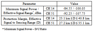
Through the ITU-R P.1546 model, the DTV service coverage has been derived based on the data in Table 7 and the radius of the TMO cell coverage. The results show that there is a 7.8 km radius at 473 MHz of TMO cell coverage. Similarly, a 6.4 km radius was derived for the TMO cell coverage at 695 MHz. On the basis of the above conditions, we calculated the spectrum efficiency according to the carrier frequency within the DTV band in Korea, 473 MHz to 695 MHz.Related to this, it has been assumed that the TETRA service area is in the shape of a square. In addition, the maximum TETRA service area limits the geometric space in the simulation. Regarding this, the simulation parameters are described in Table 11. | Table 11. Simulation Parameters for TETRA TMO |
| | Parameter | Values | | Minimum TMO Radius(Rmin) | 473MHz | 7.8 km | | 695MHz | 6.4 km | | Target Distance for TETRA Service(D) | 473MHz | 22.7 km ≤ D ≤ 27.8 km | | 695MHz | 19.3 km ≤ D ≤ 26.8 km | | TMO Frequency Range(fTMO) | 473 MHz ≤ fTMO ≤ 695 MHz | | Transmitter Power | Power Class 10 (0.6 Watt, 28 dBm) | | Data Rate / Bandwidth | 36kbps / 25kHz |
|
|
As a measure of performance, we defined the range of the enhanced spectrum efficiency by applying TETRA TMO service within the third tier of the DTV relay, as below[14],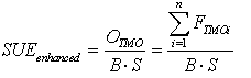 | (4) |
where, OTMO is the total occupancy in the TMO service ranges that are defined as the product of FTMO, TMO occupancy per the minimum cell, and the number of transmission in the service ranges. B is the TMO frequency bandwidth per channel and S is the geometric target space.Based on the above conditions, the range of enhanced spectrum efficiency, depending on the size of target area, was derived and is shown in Figure 9.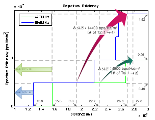 | Figure 9. Spectrum Efficiency Enhancement |
In this figure, the side of the square, i.e., the TETRA service coverage varies from 10km to 30 km so that we can examine how the target size affects the spectrum efficiency. In this regard, the steps in the Y-axis could be substituted for the number of TETRA transmitters which depends on the distance of the target area and on the carrier frequencies. Therefore, when a side length is smaller than the minimum diameters of the TMO, the transmitter cannot be installed in the target areas and there is no expectation of spectrum efficiency enhancement. In the case of the application of 41 dBμV/m, maximally one TMO cell can only be considered at the secondary user space regardless of the carrier frequencies. However, two TMO cells with a 7.8 km radius and four cells each with a 6.4 km radius could be expected when the field strength criteria is shifted to the new one, 48 dBμV/m. Spectrum efficiency can be enhanced to 4800 bps/Hz/m2 at 473 MHz and 14400 bps/Hz/m2 at 695 MHz when the spatial margins are considered by shifting the criteria of field strength from 41 dBμV/m to 48 dBμV/m.
6.2. Spectrum Management Measures
In general, spectrums have been managed in the traditional way of ‘Command & Control’ by regulators for spectrum allocation and usage decisions[15-16]. On the other hand, a key policy of communications has been to promote competition. The pursuit of this goal is challenged by a history of monopoly through public utility regulation[17]. Similarly, with terrestrial broadcasting services, the right has been emphasized under the pretext of providing free universal service to the public. However, regarding DTV conversion in Korea, DTV broadcasters do not need to be concerned about mobile service conditions because some spectrums have already been assigned for mobile broadcasting services, i.e., DMB.Therefore, some stationary unoccupied spectrums could be expected depending on the operating conditions of the regional DTV stations. According to the above results, the White Space in the DTV band could be enlarged and the spectrum efficiency enhanced when the current criteria shifts to the new ones, the standards of the FCC. In such circumstances, the DTV spectrums may be used more efficiently if the management schemes for White Space are prepared according to a new paradigm that reflects the regional criteria based on the technical analysis. Regarding this, the spectrum management procedure can be considered conceptually as shown in Figure 10.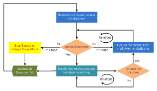 | Figure 10. DTV Idle Channel Management Process |
In this figure, the first step is applied to the current criteria to derive the spatial margins based on the data base of White Space. When there is no spatial margin in the current area or when the secondary services need to be enhanced, the inspectors iteratively change the criteria by 48 dBμV/m while watching the DTV service conditions for the protection of the major players’ rights. In connection with this, the secondary users should stop their services or change their service platform when there is no empty space on the basis of 48 dBμV/m.
7. Conclusions
In this paper, the TETRA system has been considered as a narrow band system application for DTV White Space. According to the current direction of spectrum management environmental improvement, analytical approaches have been conducted from two aspects, i.e. the compatibility of the DTV regulatory criteria and spectrum efficiency improvement.For the first aspect, the interference power according to the scenarios has been evaluated in order to investigate the possibility of coexistence with DTV. As for the results, the narrow band systems were found to be able to share DTV idle space due to their relatively lower intrusion into the DTV protection areas compared to the intrusion level of wide band systems. In the case of the TETRA TMO mode, around 70 % of DTV protection areas were found to remain even under the maximum interference conditions. In addition, 3 % or less of total TETRA MSs has been expected to exceed the limited power in the DMO mode. That is, TETRA BS is sufficient for operation at the boundary of DTV protection, i.e. -114 dBm, and the MS power class meets the maximum allowable interference power level for the DTV service.From the aspect of spectrum efficiency, empirical path loss models were used to estimate the DTV idle channels as DTV White Space based on a range of field strengths from 41 dBμV/m to 48 dBμV/m, and from around 5 km to 7 km could be expected as an extra margin for secondary user when the criteria of DTV coverage shift. Through the computational results, the spectrum efficiencies were derived in order to show the enhancement of the spectrum efficiency, and the results may be applied to the compatible regulatory criteria in order to expand the system operational margin. As for the results, the spectrum efficiency was enhanced by 14400 bps/Hz/m2, which was four times larger than the spectrum efficiency in the case of 41 dBμV/m. Thus, the proposed spectrum management scheme, as shown in the Figure 10 may be implemented to enhance spectral efficiency in the DTV spectrum.Therefore, we are able to expect not only wide band services but also narrow band services in terms of DTV White Space applications in order to use DTV idle space efficiently. Public interest and economic improvement will also be achieved with enhanced frequency efficiency. In addition, the authors would like to suggest that the various service models should be reviewed in order to allow for the successful launch of DTV White Space, also, service necessity and objectivity should be considered in order to allow for social consensus.Finally, the results indicated in the paper were derived by a simulation, and they may need extensive field tests for more practical evaluation because the environmental conditions also affect the radio propagation.
ACKNOWLEDGEMENTS
The authors would like to appreciate professors and students in Network Media Group at the graduate school of Media Design, Keio University, for their various suggestions on the study of White Space.
References
| [1] | ETSI, “Terrestrial Trunked Radio(TETRA); Voice plus Data(V+D); Part 2: Air Interface(AI)”, EN 300 392-2, V3.2.1, September 2007. |
| [2] | I. S. Jung, “Study on the DTV Conversion Policy for effective Promotion of the Analog Switch-Off Pilot Project’, Broadcasting & Communication, Vol.10-2, December 1st 2009. |
| [3] | KCC, “Confirmation of Digital Conversion Pilot Project Implementation Plan in 2010”, KCC Press release, December 23rd 2009. |
| [4] | FCC, “Office of Engineering and Technology Invites Proposals from Entities Seeking to be Designated TV Band Devices Database Managers”, DA 09-2479, November 2009. |
| [5] | MIC, “For the Use of White Space and a New Wave”, http://www.soumu.go.jp/main_content/000077004.pdf, September 2010. |
| [6] | C.-S. Ryu, K.-H. Lee, “Participation Report: World Radio communication Conference 2003”, TTA Journal, Vol. 88, July 2003. |
| [7] | FCC, “Second Report and Order and Memorandum Opinion and Order”, ET Docket No. 08-260, November 2008. |
| [8] | ITU-R, “Method for point-to-area predictions for terrestrial services in frequency range 30MHz to 3000MHz”, ITU-R P.1546-4, October 2009. |
| [9] | ATSC, “ATSC Recommended Practice: Receiver Performance Guidelines”, A/74:2010, April 2010. |
| [10] | A. Sahai, M. Mishra, R. Tandra, K.A. Woyach, “Cognitive Radios for Spectrum Sharing: Technical Appendices”, EECS, UC. Berkeley, UCB/EECS-2008-147, December 2008. |
| [11] | S. K. Palit, “Design of Wireless Communication Sensing Networks for Tunnels, Trains and Buildings”, SEAT, Messey Univ., International Journal on Smart Sensing and Intelligent Systems, Vol. 2, No. 1, March 2009. |
| [12] | S.W. Kim, “The optimization of DTV terrestrial transmission system performance” ETRI, December 31st 2002. |
| [13] | FCC, “Longley-rice methodology for evaluating TV coverage and interference,”, FCC OET BULLETIN 69, February 2004. |
| [14] | ITU-R, “Definition of spectrum use and efficiency of a radio system”, ITU-R, ITU-R SM.1046-2, 2006. |
| [15] | GAO, “Spectrum management: Better Knowledge Needed to Take Advantage of Technologies That May Improve Spectrum Efficiency”, GAO-04-666, May 2004. |
| [16] | H. Mazar, “An Analysis of Regulatory Frameworks for Wireless Communications, Societal Concerns and Risk: The Case of Radio Frequency (RF) Allocation and Licensing”, Thesis for doctor degree of Philosophy, Middlesex Univ., August 2008. |
| [17] | W.H. Lehr, J.M. Chapin, "Rethinking wireless broadband platforms", presented at "Wireless Technologies: Enabling Innovation and Growth," Georgetown Center for Business and Public Policy, Washington DC, April 2009. |
 Abstract
 Reference
 Full-Text PDF
 Full-Text HTML