-
Paper Information
- Next Paper
- Previous Paper
- Paper Submission
-
Journal Information
- About This Journal
- Editorial Board
- Current Issue
- Archive
- Author Guidelines
- Contact Us
Science and Technology
p-ISSN: 2163-2669 e-ISSN: 2163-2677
2013; 3(2A): 18-25
doi:10.5923/s.scit.201301.04
CrystmoNet Remote Access Code for Czochralski Crystal Growth Modelling
 Abstract
 Reference
 Full-Text PDF
 Full-text HTML
A. I. Prostomolotov, H. H. Ilyasov, N. A. Verezub
Institute for Problems in Mechanics, Russian Academy of Sciences, Moscow, 119526, Russia
Correspondence to: A. I. Prostomolotov, Institute for Problems in Mechanics, Russian Academy of Sciences, Moscow, 119526, Russia.
| Email: |  |
Copyright © 2012 Scientific & Academic Publishing. All Rights Reserved.
CrystmoNet code provides the ability of remote access by scheme client-server for the conjugated numerical solution of fluid and solid state mechanics problems in Czochralski crystal growth using a number of software modules: Crystmo and AnsysFluent – for fluid mechanics, MSC.MarcMentat – for radiative-conductive heat transfer and solid state mechanics, Defects – for defect formation and Tecplot-360 – as graphic postprocessor. Conjugated modelling is provided by the developed software interface. CrystmoNet code implements the client-server interaction at two operating platforms: MicrosoftWindows client receives the licensed remote access to server, where the above-mentioned software modules are installed for calculations at Unix-like operating system. The solution of conjugated fluid and solid state mechanics problems in Czochralski crystal growth is shown on the examples.
Keywords: Modelling, Remote Access Code, Czochralski Crystal Growth
Cite this paper: A. I. Prostomolotov, H. H. Ilyasov, N. A. Verezub, CrystmoNet Remote Access Code for Czochralski Crystal Growth Modelling, Science and Technology, Vol. 3 No. 2A, 2013, pp. 18-25. doi: 10.5923/s.scit.201301.04.
Article Outline
1. Introduction
- Czochralski (Cz) crystal growth modelling has became an important scientific problem, which is the subject of many publications. On the one hand, this is due to the great practical importance of this technology and ever-increasing requirements to the crystal quality and size. On the other hand, there is the considerable scientific interest to a study of complex interaction of various physical processes influencing on the required crystal parameters. Modern numerical modelling is focused on the conjugated solution of fluid and solid state mechanics problems in Cz crystal growth[1]. The basis of most these works is specialized software codes, which have their own grid generators, solvers and graphics tools. An initial basis of the present work was a development of similar specialized code, too. It was based on our own numerical approach and software modules for conjugated heat transfer in Cz silicon (Si) hot zone[2-4] and the defect formation in dislocation-free Si crystals[5,6]. However, the development of such codes for new technologically important mechanical models of fluid and solid state usually faces with known difficulties caused by limited resources of research groups. Therefore, in recent years we have developed CrystmoNet program code on the basis of joint using our Сrystmo, Defects modules and well-known commercial program codes for fluid and solid state mechanics problems: AnsysFluent – for fluid mechanics (Fluient module), MSC.MarcMentat – for radiative-conductive heat transfer and solid state mechanics (Marc and Mentat modules) and Tecplot-360 – for graphic representation of results (Tecplot module). This paper describes the general approach for Cz modelling, the content of CrystmoNet and remote interaction of its modules and examples of Cz modelling. The examples are given in the application to Redmet-90M Cz puller for a large diameter Si single crystal growth[7]. The detailed discussions of the numerical results are contained in the published papers[8-11].
2. Description of Program Code
2.1. The General Approach for Cz Modelling
- The conjugate radiative-conductive model (RCM) is applied to calculations of heat transfer in Cz hot zone (Figure 1). The approximation and solution of equations are carried out on the basis of finite element method (FEM). After FEM calculation the temperature distributions on the boundaries of melt and crystal are sent for calculations of convective heat transfer (CHT) in a melt by finite volume method (FVM). The calculated velocity field is used on next RCM iteration. The crystallization process and shape of liquid-solid interface (LSI) may be calculated in RCM or CHT models.
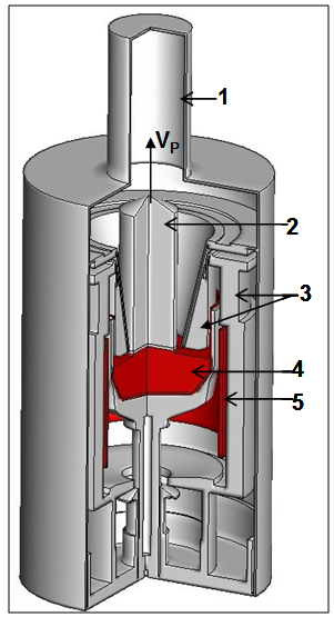 | Figure 1. The hot zone of Redmet-90M Cz puller: 1 - tank, 2 – crystal, 3 – thermal shields, 4 – melt, 5 – heater; VP – crystal pulling rate |
2.2. The Composition of Program Code, the Remote User’s Access and File’s Exchange
- CrystmoNet code provides the ability of user’s telecommunication access by scheme client-server on two operating platforms: MS Windows – at user's computer and Unix-like – at the remote server. CrystmoNet-Shell module and pre/postprocessor Mentat are installed on user’s computer. CrystmoNet-Shell module is the shell program, which controls all operations of CrystmoNet code. The shell program manages a distributed computing environment and provides the interface between the system components, which are executed on server and client computer. License server and the subject-oriented - Crystmo, Defects, Marc, Fluent modules, and Tecplot - graphical postprocessor are installed at server computer. The data exchange between client and server is carried out according to the scheme shown in Figure 2. The composition and structure of the code are designed for remote calculations with the use of high-performance servers. On a logical level the components of the code are distributed between the client’s computer, License server computer and the computational server (computing cluster). Client computer with pre/postprocessor Mentat is used for data input: the geometry of hot zone and parameters, as well as for graphic output of contours and graphs on display and printer. The modules - Crystmo, Marc and Fluent are executed on the server under Unix-like operating systems. The shell program - CrystmoNet-Shell opens the window with tabs on computer screen of user (see Figure 3: Server.data, Marc+Crystmo, etc.), which contains the input data for modules, the files to copy (from client to server and back), and command's buttons for a start of modules and Tecplot graphic postprocessor. The control of the number of the concurrent applications is managed by License server. The shell program executing on client’s computer provides start/stop of code's components and data's transfer between them.
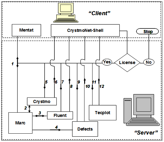 | Figure 2. The functional diagram of client-server interaction with the directions of file exchange between modules for remote work with CrystmoNet code |
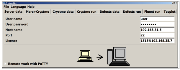 | Figure 3. Server.data tab for user's registration for license work on the remote server |
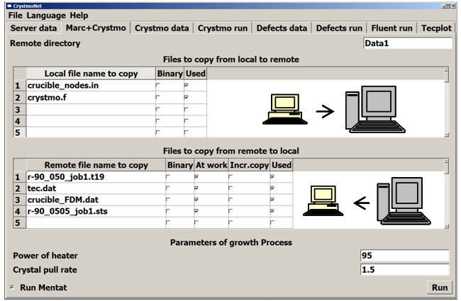 | Figure 4. Marc + Crystmo tab for a transfer of files from client to server and back for executing the single module – Marc or Marc+Crystmo jointly executing |
2.3. Marc Module with Mentat Pre/postprocessor
- Marc module includes Mentat graphic pre/postprocessor[12], in which the preparation of input data for Marc solver is carried out: the setting of the geometry of hot zone and its grid division into finite elements (Figure 5).
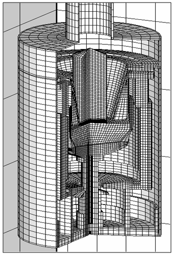 | Figure 5. The illustration of FEM grid for Cz hot zone, which has been generated and plotted by Mentat module |
2.4. Crystmo Module
- Crystmo module calculates the hydrodynamics and heat transfer in a melt for Cz crystal growth. Three-dimensional Navier-Stokes and heat transfer equations are solved together in Boussinesq’s approximation and cylindrical coordinates by FVM[2,3]. Physical parameters (density, viscosity, thermal conductivity and heat capacity) are assumed to be constant in a melt. The action of constant and rotating magnetic fields on the convective heat transfer in a melt may be taken into account[14]. The calculation grid, the adjusting and physical parameters are specified in tabular form in Crystmo.data tab. The temperature distributions on boundaries of a melt are taking into to account to the calculated data of Marc module for radiative-conductive heat transfer in Cz Si hot zone. For its transfer from FEM grid of Marc module on FVM grid of Crystmo module the data interpolation is done. The data for the file exchange between Marc and Crystmo modules are presenting in Tecplot format. For conjugated Marc+Crystmo execution the velocity components of a melt flow calculated by Crystmo are interpolated on FEM grid and then are passed to Marc in Tecplot format. File's exchange between client and server, and the starting of Crystmo module are done in Crystmo.run tab, which in appearance is similar to Marc+Crystmo tab (Figure 4).
2.5. Fluent Module
- Fluent is used as the hydrodynamic module for Cz modelling, which has the additional possibilities: the solution of Navier-Stokes and heat transfer equations in a complex domain (for example, in a double crucible), with taking into account of crystallization and turbulent models of fluid dynamics. The physical parameters of liquid or solid materials (viscosity, thermal conductivity and heat capacity) may be temperature dependent. For preparation of input data for Fluent solver and for imaging the numerical results the built-in image pre/postprocessor is used[15]. The examples of individual application of Fluent module for Cz modelling are known and fairly numerous, one of them is given in[16]. However, the examples of its joint using with Marc module are absent. In CrystmoNet code the conjugation of Marc and Fluent modules is built on basis of file's exchange. For this purpose, we have elaborated the special C++ subroutines, which allow user's input/output of data: the input of the temperature distributions on boundaries (of melt and crystal) in according with Marc results and output of velocity components in a melt after Fluent calculation. During the data transfer the same interpolation as for conjugated Marc+Crystmo calculations is done.
2.6. Defects Module
- Defects module calculates the recombination and diffusion of intrinsic point defects - IPD (vacancies and Si interstitials)[5] and the microdefect's formation[17] in growing dislocation-free Si single crystals. For this calculation the crystal temperature field is used, which has been calculated by Marc+Crystmo or Marc+Fluent modules. The system of equations for calculation of IPD concentration and the microdefect density is solved by finite difference method (FDM) in the crystal. FDM grid and the physical parameters are set in tabular form in Defects.data tab. The file exchange between client and server, and the run of Defects module is done in Defects.run window, which in appearance is similar to Marc+Crystmo tab (see Figure 4). The data for file exchange between Marc and Defects modules are set in Tecplot format. During file exchange the data interpolation is done as in conjugated calculation by Marc and Crystmo or Fluent modules.
2.7. Tecplot Module
- Tecplot module is used as the universal and most efficient graphic postprocessor that does the graphic images of numerical results obtained by different numerical methods (FEM, FVM and FDM). The graphic tabs of Tecplot module is simple and easy for graphic editing of numerical results[18]. The run of this module is done in Tecplot window (Figure 4). The file exchange between client and server provides loading the numerical results in Tecplot format for each of the calculation modules (Marc, Crystmo, Fluent and Defecs). An analysis of the numerical solutions is done by graphic tools of Tecplot module and by means of Mentat and Fluent postprocessors, too.
3. Examples of Cz Modelling
- Let's consider the examples of the application of CrystmoNet code for the conjugated Cz modelling. For adequate modelling of thermal field in a crystal it is important to take into account of the melt convection and the crystallization process. The convective heat transfer in a melt is considered in the crucibles of different shape (usual single crucible, double or more complex crucibles) under the effect of crystal or/and crucible rotation, thermal gravitational and thermal capillary convections. For the semiconductor melt (such as Si) may be taken into account the constant and rotating magnetic fields. The calculations of Cz heat transfer are based on the conjugation of RCM model of Marc module and CHT models of convection in Crystmo and Fluent modules. The calculations of stress state and microdefect formation in a crystal are done on basis of the results of such conjugated thermal modelling in Marc module (for "thermal mechanical" tasks) and in Defects one respectively.
3.1. Conjugated Heat Transfer
- For Marc+Crystmo conjugated option the calculations are carried out in the following sequence. At the beginning the calculations are carried out by Marc module for conductive-radiative heat transfer (without taking into account of velocities field in crystal and melt) and at an initial power of heater. For taking into account of the crystallization in Marc module the transition layer between melt and crystal in the temperature range TS
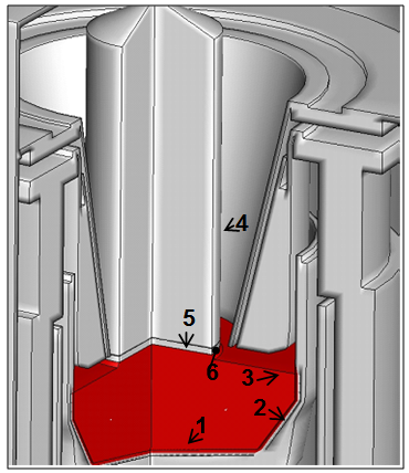 | Figure 6. The marked boundaries of a melt, on which the temperature distributions are recorded in the exchange file by Marc module for the following using in Crystmo or Fluent modules. Here: 1, 2 – bottom and lateral crucible walls, 3 – free melt surface, 4 – lateral crystal surface, 5 – layer of crystallization, 6 – control point on LSI edge |
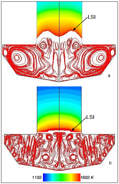 | Figure 7. The thermal field in crystal and streamlines in melt after conjugated Marc and Fluent calculations: a – W-shape of LSI for large heater power, b – concave shape of LSI for optimal heater power |
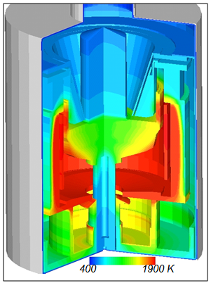 | Figure 8. The thermal field in Cz hot zone after conjugated Marc and Fluent calculations |
3.2. Conjugated Stress and Defects Calculations
- During crystal growth process the thermal conditions have a significant influence on the stress state in the large diameter Si single crystals. By means of Marc module it was calculated the thermal stress state of a 100 mm diameter Si single crystal on one growth stage for an estimation of the appearance of critical stresses, which cause the plastic deformation and the generation of dislocations (Figure 9a). The calculated values do not exceed the critical stress. Its maximum value (7.6 MPa) is achieved on the lateral crystal surface closely to LSI and it is caused by the largest temperature gradients in this area. The stress decreases rapidly with the increasing distance from LSI.
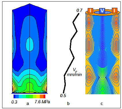 | Figure 9. The conjugated modelling the stress state and defect formation in Si growing crystal: a – the field of von Mises stress; b,c – the change of pulling rate Vp during growth process and corresponding I/V-distributions of microdefects |
4. Conclusions
- Until now for Cz crystal growth modelling there is the limited use of well-known commercial codes of extensive application: the such as AnsysFluent – for fluid mechanics and MSC.MarcMentat – for solid mechanics problems. Its usual application is related with a single solution of non-conjugated problems. It may be the radiative-conductive heat transfer, melt fluid dynamics or stress state in a crystal. For the conjugate Cz modelling the problem-oriented Cz commercial codes are used widely (CGSim, FEMAG, STHAMAS, CrysMAS et al). For many years these codes were developing in close contact with Cz technological practice and therefore well adapted for such calculations. It is an indubitable competitive advantage of these codes. The disadvantage is a rather narrow set of physical models, especially for solid mechanics in comparison with MSC.MarcMentat. Moreover the user is limited by possibilities of models included in these codes, and the independent integration of user's or other program modules is impossible without the developers of these codes.The present paper reviews one possible approach of integrated use of user's (author's) Crystmo and Defects modules and the codes of extensive application in Cz modelling: AnsysFluent, MSC.MarcMentat, Tecplot-360. This approach is implemented in CrystmoNet code and allows the remote access by means of client-server scheme. We took into account the desire of the majority of our colleagues and especially students for a work on their own computers (client) with using the most widely operating systems (MS Windows). It was elaborated non-standard network version of CrystmoNet code for a work at two operating systems: MS Windows – for user's work on client-computer and Unix-like – for all calculations on a remote server. The program-shell of CrystmoNet code manages by the distributed computing environment and provides the interface between the code's modules, which function on server and client computers. This version may be easily expanded by user's own modules for special applications of fluid and solid state mechanical problems emerging in Cz crystal growth technology. In the above examples of Cz modelling for conjugated heat transfer, stress state and defect formation in a crystal there is presented a little part of parametric calculations carried out by CrystmoNet code during an elaboration of hot zone for Redmet-90M Cz puller.
ACKNOWLEDGEMENTS
- We thank the Russian Foundation for Basic Research for the financial support of projects (11-08-00966, 12-02-01126, 12-02-90027-Bel) and Dr. Ezhlov (JSC "Giredmet") for the technical support and the access to MSC.MarcMentat and Tecplot-360.