R. De Luca1, O. Faella1, P. Zozzaro2
1Physics Department “E. R. Caianiello”, University of Salerno, Fisciano (SA), Italy
2Physics Laboratory at I.T.I.S. “G. Gatta”, Sala Consilina (SA), Italy
Correspondence to: R. De Luca, Physics Department “E. R. Caianiello”, University of Salerno, Fisciano (SA), Italy.
| Email: |  |
Copyright © 2014 Scientific & Academic Publishing. All Rights Reserved.
Abstract
Geometrical optics is used to devise and study a spherical thick lens for concentrating solar light onto a multilayered photovoltaic cell. It is found that the desired requirement of maintaining the uniformity of the light bundle and the direction normal to the plane of the photovoltaic device can be met. Construction details are specified for a given concentration ratio. Spherical and chromatic aberrations are seen not to affect the desired behavior of the optical system.
Keywords:
Light concentration devices, Solar energy, Concentrated photovoltaic systems
Cite this paper: R. De Luca, O. Faella, P. Zozzaro, Light Concentration by Means of Spherical Thick Lenses, International Journal of Optics and Applications, Vol. 4 No. 4A, 2014, pp. 1-5. doi: 10.5923/s.optics.201401.01.
1. Introduction
Concentrating solar light is important for a variety of renewable energy applications. In devising a concentrated photovoltaic (CPV) system [1], for example, one requires a bundle of concentrated light to impinge perpendicularly and uniformly on a planar surface where a multilayered semiconductor solar cell lies. These conditions (concentration, preferred normal direction, uniformity of the light bundle) can be met by optical systems of many kinds. As a first example, we might mention a Cassegrain optical system [2] made of two confocal parabolic mirrors facing each other as in fig. 1. In this system, light coming from infinity is concentrated in a region close to the common focal point F.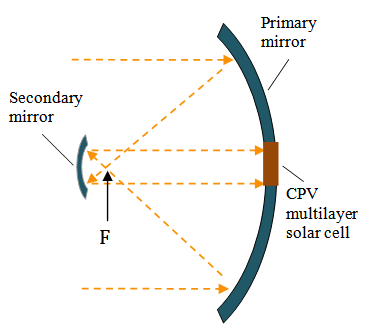 | Figure 1. Solar light is concentrated by a Cassegrain optical system consisting of two confocal parabolic mirrors facing each other. The primary mirror gathers light rays coming from infinity, projecting them in the vicinity of the common focus F. The secondary mirror sends concentrated light uniformly on the CPV multilayer solar cell. The direction of the light rays is orthogonal to the plane in which the CPV system lies |
In this case, however, it is necessary great precision and care in the fabrication of the optical system. One can therefore ask whether a single lens can accomplish the same task of this mirror system. From geometrical optics, under the hypothesis of paraxial rays, we can write, for a spherical thick lens [3]: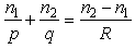 | (1) |
where n1 and n2 are the indices of refraction of the medium and of the lens, respectively, p and q are, in the order, the positions of the object and its image, and R is the radius of curvature of the spherical lens. For  , we obtain the position of the first focus F in q=f, so that:
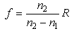 | (2) |
Thus, if we let the second surface to have a focal point coincident with F, we obtain, in a second refraction, light rays emerging parallel to the incoming direction, as shown in fig. 2. In the present work, after having carefully considered spherical and chromatic aberrations, we give details on the optical characteristics of this system, specifying all dimensions of the spherical thick lens able to concentrate light according to a given concentration factor.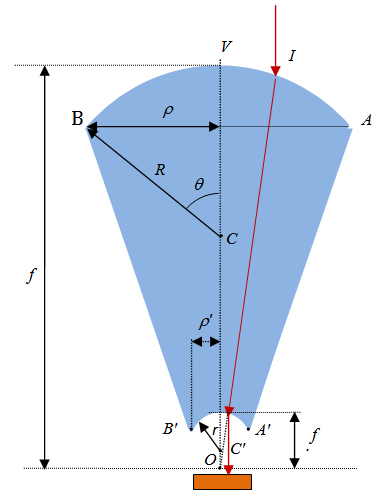 | Figure 2. Solar light is concentrated by a spherical thick lens. Both sides of the lens are spherically shaped, with different radius of curvature: the upper and lower surfaces have radii of curvature R and r, respectively. The two sides have a common focus in O |
2. The Optical System
In this section we give details on the expected optical behavior of the system schematically described in fig. 2. By the thick lens relation corresponding to the bottom side of the lens, we may write a relation similar to Eq. (2) for the quantity f’ shown in fig. 2: | (3) |
In this case we have exchanged the indices of refraction in (1) and have required  , obtaining the position of the second focus in
  In order to fix our ideas, let us take n1=1 and n2=n, so that:
 | (4a) |
 | (4b) |
We now choose our system to be a solid of revolution obtained by rotating the planar geometry represented in fig. 2 about the optical axis containing the segment OV. By considering the triangles OAB and OA’B’ in fig. 2, we may write the radii  and
and  being one half of the upper and lower diameters AB and A’ B’, respectively, as follows:
 | (5a) |
 | (5b) |
where  is the angle between the segments CB and CV. From Eqs. (4a-b) and (5a-b) we can derive the following simple proportions:
 | (6) |
The geometrical concentration ratio Cgeo can thus be thus defined as the ratio between the projection of the upper and lower spherical areas as follows: 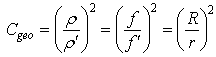 | (7) |
Therefore, it could appear that we might obtain an arbitrarily high concentration ratio Cgeo. In what follows we shall consider this factor to be Cgeo 400. Nonetheless, problems could arise from spherical and chromatic aberrations. In this way, before considering the total volume and the total mass of the lens, in the next section we shall briefly consider the effects of these types of aberration.
3. Aberrations
In the present section we shall give a brief account of the spherical and chromatic aberrations in the system, noticing that they do not affect the predicted optical behavior described in the previous section.
3.1. Spherical Aberrations
By starting with spherical aberrations, we look for the intersection of a light ray coming from infinity and the optical axis of a spherical thick lens. This intersection depends on the abscissa on which the incident ray impinges on the spherical surface. In this way, rays from infinity are not focused in a single point, so that the phenomenon of spherical aberration arises. In order to compute the maximum deviation from the value of f calculated by means of the paraxial axis hypothesis in (2), we construct the path of the light ray as in fig. 3. The light ray coming from infinity is thus seen to impinge on the spherical interface in P0=(x0,y0). The angles  and
and  are comprised between the normal line ln and the incident and refracted rays, respectively. These two angles are related by Snell’s law, so that:
 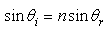 | (8) |
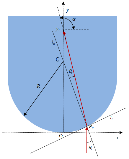 | Figure 3. Schematic representation of the path of a light ray coming from infinity and refracted inside a thick spherical lens of radius R. The angle of incidence in P0 is , the angle the refracted ray makes with the normal is , the angle the refracted ray makes with the normal is  |
As it can be noticed from fig. 3, the refracted line is at an angle  from the x-axis, so that the equation of this line is:
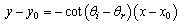 | (9) |
We define yI = y(0), so that, by setting  and
and  and by considering (8), we can write yI entirely in terms of
  as follows:
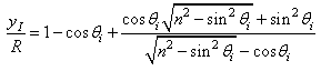 | (10) |
By a series expansion of the cosine and sine functions to third order in  we obtain:
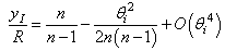 | (11) |
Therefore, we can estimate the error  we make, by assuming paraxial rays, in computing f for an incident ray forming an angle
  with the normal to P0, the refracted line is at an angle
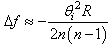 | (12) |
By doing the same with the spherical interface of radius r, by elementary geometry we first notice that the new incident and refracted angles  and
and  are related to
  and
and  by the following simple relations:
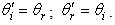 | (13) |
In this way, we find, by the same type of analysis: | (14) |
so that: | (15) |
For a choice of the maximum angle  and of the radius R=24.0 cm, we can compute the maximum deviation from f to be about
  =3.42 cm for n=1.60 and about
  =4.51 cm for n=1.49. The corresponding variations of f’ will be
  Therefore, the excursion of the focuses in this system is rather large.The question now is, will the calculated spherical aberrations affect the direction of the rays coming out of the lens from the second interface and the uniformity of the bundle, thus hindering the correct functioning of the optical system proposed in the present work? In order to see this, let us assume that, for some reasons, we allow variations of both f and f’ in the system. Because of (4), being only the focal lengths to vary, by taking the derivative of both sides and by approximating the infinitesimal variations of f and f’ to
  as above, we have:
 | (16) |
In this way, the system will behave in the same way as predicted in section 2, if the ratio of the two variations is such that:  | (17) |
which, because of (6), is exactly what found in Eq. (15).
3.2. Chromatic Aberrations
We next consider chromatic aberrations due to dispersion of light inside a dielectric. According to Cauchy’s equation, the index of refraction depends on the wavelength of the electromagnetic radiation in the visible range roughly as follows: | (18) |
where A and B are opportune coefficients, which depend on the particular material used. However, we are not particularly interested in the exact way n changes with  for reasons which will appear clear later. We only need to know that, if n varies in some way, Eqs. (4a) and (4b) predict variations
  and
and  which may be written as follows:
 | (19a) |
 | (19b) |
Once again we obtain that the ratio between the variations  and
and  is equal to the ratio of the radii R and r, thus verifying (17) as in the previous case of spherical aberrations. Therefore, even though chromatic aberrations modify the focal lengths for rays of different wavelength, these variations do not affect the way the system concentrates light on the CPV cell for the same reasons explained at the end of the previous subsection.
4. Dimensions and Mass
Under the hypothesis that Cgeo in the present section we specify the dimensions of the optical system in fig. 2. In this case, the ratios in Eq. (6) are
 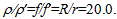 In order to intercept a not negligible solar radiation power and to illuminate a CPV cell of about 1cm2, we choose
  cm so that
  =0.60 cm. We can thus estimate the radiating power harvested by this optical system by considering the incoming power to be
  , where ES is the irradiance of the direct solar radiation, whose peak value is about 0.9 kW/m2. By making the assumptions that nearly normal incidence occurs at the upper and lower glass interfaces, so that the transmittances [4] can be set equal to T(n)=4n/(n+1)2 and
  , respectively, and by considering the power dissipated in the glass as negligible, we can write the transmitted power as:
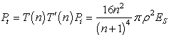 | (20) |
By now assuming a 35% efficiency of the CPV cell in converting radiating energy in electrical energy, we end up with an estimated value of the electrical power generated by a single element (optical system + CPV cell) of 0. 32 Pt. We still need to completely specify other geometrical quantities in the optical device. In order not to incur into too much discrepancy with the assumption of quasi-normal incidence, we might take the angle  In this way, from (5a) and (5b) we obtain R=24.0 cm and r=1.2 cm, respectively. We shall keep these geometrical quantities as fixed and determine, on the basis of different choices of the index of refraction of the lens, the focal lengths, f and f’. Next, consider the density of the material used for the thick lens to be denoted by dL, so that the mass M will be given by M = dL V, where V is the total volume of the lens itself. In order to calculate V, let us first calculate the volume VTC of the truncated cone by means of the difference between the cone with base radius
  and height
 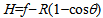 and the cone with radius
  and height
 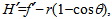 so that
  and:
and: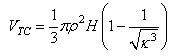 | (21) |
Let us now define the heights of the upper and lower spherical domes in the optical system, respectively, as follows: 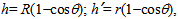 so that h/h’=f/f’. The missing volume to VTC is thus given by the difference between the volume of the upper and lower spherical domes
  defined as follows
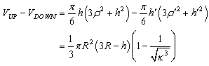 | (22) |
In this way, the total volume of the optical system can be written as follows: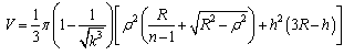 | (23) |
Consider first a glass with index of refraction n=1.6. From (4a) and (4b) we find f =64.0 cm and f’ =3.2 cm, respectively. By now taking specifying the density of the glass to be dL = 2.40 g/cm3, we calculate the volume of the system studied and, successively, its mass. By evaluating V from (23), we have 11590 cm3, so that M=27.8 Kg. Finally, from (20) we obtain at most a radiating power Pt=36.5 Watt, and an electric power of about 12.8 Watt. One could also wish to look for lighter materials with roughly the same index of refraction, in order to construct an optical device for practical applications. For example, we might choose to use transparent thermoplastic (plexiglas), with an index of refraction n=1.49 and a density of about 1.18 g/cm3. By going through the same calculations, for  cm and
  we obtain f =73.0 cm and f’ =3.65 cm. The volume of this system can thus be calculated to be roughly 12940 cm3, so that the final mass is reduced to about 15.3 Kg. Therefore, even though the space occupied by plexiglas is higher than glass with n=1.6 and with a higher density, we have a conspicuous reduction in the weight of the system. Finally, we can see that the maximum transmitted power in this case is Pt=37.6 Watt, for a peak electric power generated by the cell of about 13.2 Watt.
5. Conclusions
We have studied the optical behavior of a spherical thick lens for light concentration on a concentrated photovoltaic (CPV) cell. The proposed optical system looks like a transparent glass cone to which we take off the inferior part, whose interface is spherically shaped, and to which we add a superior spherical dome. We have noticed that the system can gather incoming light from infinity concentrating it uniformly and with normal incidence on a plane perpendicular to the incoming rays. Spherical and chromatic aberrations are seen not to affect the optical behavior predicted through the simplifying approximation that rays are monochromatic and paraxial. This happens because the system is constructed in such a way that the variation of the focal length f for the first convex portion of the optical device is compensated by a proportional variation of the focal length f’ of the second concave interface. In this respect, the system can be used as a concentrator of solar light for a concentrated photovoltaic (CPV) cell. In the present work the transmitted radiating power to the CPV cell is calculated under the assumption of normal incidence of light on the first and second interfaces and of negligible power dissipation inside the glass. Under these hypothesis, a device made of transparent thermoplastic (plexiglas), with mass of about 15.3 Kg, a radial aperture  cm, and total length of about 70.0 cm, is seen to concentrate solar light with a concentration factor Cgeo
 400 into a circular CPV cell, of approximately 1.1 cm2 of area and with 35% efficiency, giving out an electric power output of about 13.2 Watt. These studies, essentially based on geometrical optics, and the specific quantities described in the present work may trigger experimental and analytical research on the interesting topic of optical devices for CPV cells illumination.
References
| [1] | D. C. Law, R. R. King, H. Yoon, M.J. Archer, A. Boca, C.M. Fetzer, S. Mesropian, T. Isshiki, M. Haddad, K. M. Edmondson, D. Bhusari, J. Yen, R. A. Sherif, H. A. Atwater, N. H. Karam, “Future technology pathways of terrestrial III-V multijunction solar cells for concentrator photovoltaic systems,” Solar Energy Materials & Solar Cells, vol. 94 pp. 1314-1318, Aug. 2010. |
| [2] | Welford, W. T., 1991, Useful Optics, The University of Chicago Press, Chicago. |
| [3] | F. W. Sears, F. W., Zemansky, M. W., Young, H. D., 1977, University Physics, 5th ed., Addison-Wesley, Reading. |
| [4] | Yadav, P., 2006, Engineering Physics, Discovery Publishing House, New Delhi. |
| [5] | Sharma, K. K., 2006, Optics, Academic Press, Burlington, MA. |
 Abstract
 Reference
 Full-Text PDF
 Full-text HTML