-
Paper Information
- Paper Submission
-
Journal Information
- About This Journal
- Editorial Board
- Current Issue
- Archive
- Author Guidelines
- Contact Us
International Journal of Mechanics and Applications
p-ISSN: 2165-9281 e-ISSN: 2165-9303
2013; 3(A): 13-21
doi:10.5923/s.mechanics.201308.03
Wear Outcomes of a Metal on Metal Disc Arthroplasty – A Computational Model
 Abstract
 Reference
 Full-Text PDF
 Full-text HTML
Sanghita Bhattacharya, Second Vijay K. Goel
Engineering Center for Orthopaedic Research Excellence (E-CORE), Departments of Bioengineering and Orthopaedic Surgery, University of Toledo, and Toledo, OH
Correspondence to: Sanghita Bhattacharya, Engineering Center for Orthopaedic Research Excellence (E-CORE), Departments of Bioengineering and Orthopaedic Surgery, University of Toledo, and Toledo, OH.
| Email: |  |
Copyright © 2012 Scientific & Academic Publishing. All Rights Reserved.
Earlier efforts in areas of hip and knee arthroplasties suggest that wear debris, could initiate inflammatory responses leading to peri-prosthetic osteolysis and bone resorption at the implant-bone interface. Aseptic loosening of implants due to particle induced osteolysis is the primary cause of revision surgeries. Bench top wear tests as well as bioreactivity studies have emerged as a powerful preclinical tool. However there is still a gap between the in vitro bench-top wear tests and the retrieval test cases. Predictive finite element modeling based on wear-laws serve as an excellent design tool for parametric analyses. In such models, the effect of individual variables can be judged independently leading to an understanding of the role of that parameter on the final outcome. Comparative wear data for artificial cervical discs are sparse. The purpose of this study is to characterize the wear performance of a metal-on-metal (MOM) ball and trough artificial disc and compare the wear performance of this device to metal-on-polymer (MOP) ball-on-trough artificial disc in an in-vitro and in-vivo simulation using FE modeling. Our hypothesis is that wear rates and patterns in an in-vivo scenario differs from machine simulated data and is also dependent on the material combination chosen.
Keywords: Wear, Osteolysis, Total disc arthroplasty, Metal-on-metal
Cite this paper: Sanghita Bhattacharya, Second Vijay K. Goel, Wear Outcomes of a Metal on Metal Disc Arthroplasty – A Computational Model, International Journal of Mechanics and Applications, Vol. 3 No. A, 2013, pp. 13-21. doi: 10.5923/s.mechanics.201308.03.
1. Introduction
- Although disc arthroplasty is more than two decades old, it is still a newer technology in comparison to the larger joints.While developing the disc arthroplasty designs; we have utilized scientific knowledge from mature technologies including hips and knees. For instance, the materials adapted for the total disc arthroplasties (TDA) are metal on polymer (MOP) and metal on metal (MOM). These are similar to the materials being used for hip replacement systems. Along with other issues, device debris led osteolysis still remains an enduring concern for orthopedic implants[1]. Preclinical bench top simulator tests based on ASTM/ISO standards have been developed to predict wear based on an understanding of biomechanics and wear-related topics[2]. Although physical simulators have evolved over a period of time, they still have several shortcomings especially the ones designed for the evaluation of TDA. These simulators are expensive and are also a time consuming process to assess wear[3]. In addition, the spine wear simulators have a fixed center of rotation (COR), which is not representative of the variable COR that the TDA designs are trying to emulate. Furthermore, the effect of a malpositioned/misaligned implant is difficult to simulate because there are no current provisions to simulate adjoining structures (e.g., ligaments, annulus). This plays a crucial role in modulating the TDA wear. Additionally, inter station data variability is common; , therefore these simulations are more useful for comparing one design to another, than for actually simulating in vivo scenarios.In order to address the aforementioned limitations, mathematical wear-predictive models have been utilized in the areas of the hip, knee and spine to predict wear patterns [4-8]. Maxian et al.[6] are the first to implement the classical Archard’s wear law[9] to simulate wear in total hip arthroplasty (THA) using finite element methods. A, probabilistic model was developed by Knight et al.[4] to understand the effects of variations of both alignment and constraint, as well as other such conditions on the wear of the polymeric insert in total knee arthroplasty (TKA). Several groups developed mathematical models for assessment of disc arthroplasty wear based on the ideas from hip and knee wear simulations[3,8]. These models, in essence, mimicked the test conditions simulated in the wear simulators and have thus limited application. In order to bring the model’s predictions closer to the wear observed in retrieved implants, these models need further refinements.Wear is a multifactorial problem[10] in which implant-specific, patient-specific and surgeon-specific factors play an important role. Our group incorporated the Archard’s wear law in a finite element model of the cervical ligamentous functional spinal segment[11] in order to address these issues. This model allowed us to delineate the role of ligaments and other structures on the wear amount and pattern in TDA design similar to ProDisc-C. In addition, the predicted wear was in line with the wear outcomes observed in retrievals. This study also represents a case of non-uniform wear distribution as seen in an in vivo setting. This study, along with others, refuted the arguments presented by other researchers who claim that polymeric wear in spinal devices might not be a clinically relevant issue based on their in vitro wear data from laboratory simulations. The aim of the current manuscript is to understand the effects of different material combinations (metal-on-polymer vs. metal-on-metal) for a single TDA design, by utilizing a ligamentous functional spinal unit (FSU) model described below.
2. Methods
- First the finite element models were developed for TDR alone and TDR placed within a FSU. The technical details of the model formulation are provided elsewhere[11]. Then, these models were coupled with Archard’s law to predict TDR wear as a function of time for a maximum of 10 million cycles. Two finite element models were formulated to study the wear characteristics of TDR. One model includes the presence of spinal structures, while the other does not.Model of the TDR alone (TDR only)The artificial cervical disc was comprised of a superior metallic ball and an inferior trough design (Young’s Modulus= 220 GPa and Poisson’s ratio= 0.32) similar to Prestige (Medtronic Sofamor Danek). Both the inferior and the superior device endplates were meshed using hexagonal elements. The sliding interactions at the metallic ball-trough interface were simulated as a hard contact (pressure-over closure relationship without physical softening) with a coefficient of friction of 0.2 at the interface (Fig 1.A).TDR in FSU model (TDR+FSU)The experimentally validated ligamentous intact C5-C6 FE model[11] was modified to accommodate the artificial disc. The artificial disc was placed symmetrically in the disc space as per the surgical procedure that involved removal of the anterior longitudinal ligament (ALL), anterior annulus, entire nucleus, portions of the posterior annulus and the posterior longitudinal ligament (PLL) at the C5-C6 region. All other structures, including the remaining annulus, uncinate processes and Luschka’s Joints, were preserved (Fig 1.B). The vertebral endplates were modified in order to match the contours of the device endplates. Various spinal structures within the segment were appropriately simulated to mimic their functional characteristics. The vertebral bodies were defined as cancellous bone cores surrounded by 0.5-mm–thick cortical shells. The facet joints were modeled using surface definitions where the surface gaps between each facet region was assumed to be 0.5-mm based on prior computed tomographic imaging data. The facets were oriented at approximately 45 degrees from the horizontal plane, with some variation in the sagittal plane. The annulus fibrosis was modeled as a composite structure. The ligaments of the lower cervical spine, including the anterior longitudinal ligament (ALL), posterior longitudinal ligament (PLL), interspinous ligament, ligamentum flavum, and capsular ligaments, were modeled as three dimensional truss elements (T3D2). Furthermore, they allowed to behave nonlinearly via a ‘‘hypoelastic’’ option. An in-depth description of each anatomic structure and the model itself is provided elsewhere[11, 15].Boundary conditionsThe TDR-only model kept the inferior-most aspect of the inferior metal end plate in a fixed position. The TDR+FSU model kept the C6 vertebra completely constrained in all six degrees of freedom at the inferior end plate, inferior facets, and inferior part of the spinous process.LoadsThe TDR-only model, applied a preload through a coupled point on the superior surface of the superior device end plate. The TDR+FSU model applied an axial load using the follower load concept. A set of connector elements was used in the model to simulate the follower type compression on the segment—an approach that replicates the effect of muscle forces in vivo. In both models a varying compressive load of 50 to 150 N (ISO 18192) was applied. Next, flexion/extension (Flex/Ext) of ±7.5°, lateral bending (LB) of ±6° and axial rotation (AR) of ±4° via time-dependent amplitudes within a single-loading step were applied at 1 Hz with the specified phase difference consistent with ISO 18192.
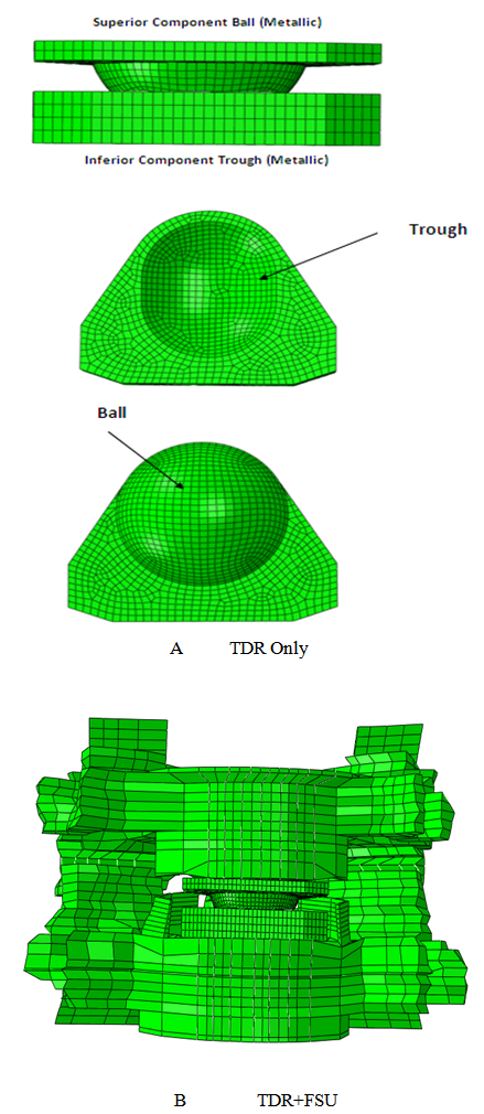 | Figure 1. A. FE model of metal on metal ball on trough implant (TDR Only) B. FE model of disc implanted onto a FSU (TDR+FSU) |
3. Results
- TDR Only vs. TDR+FSU (MOM)
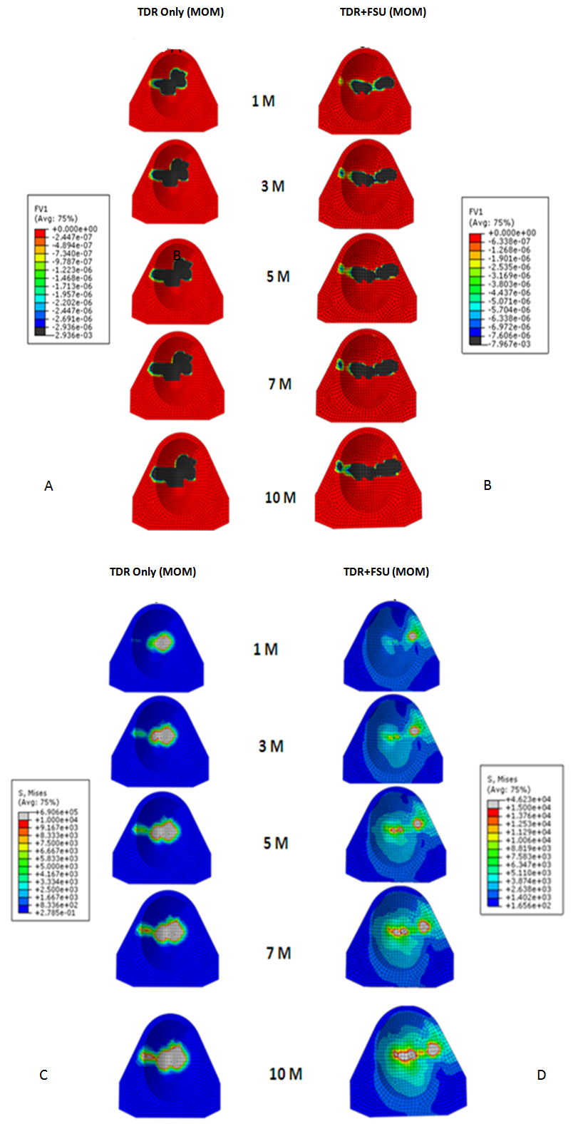 | Figure 2. Linear wear patterns (A&B) and stress patterns (C&D) for TDR only and TDR+FSU simulation for 1,3,5,7 and 10 million cycles |
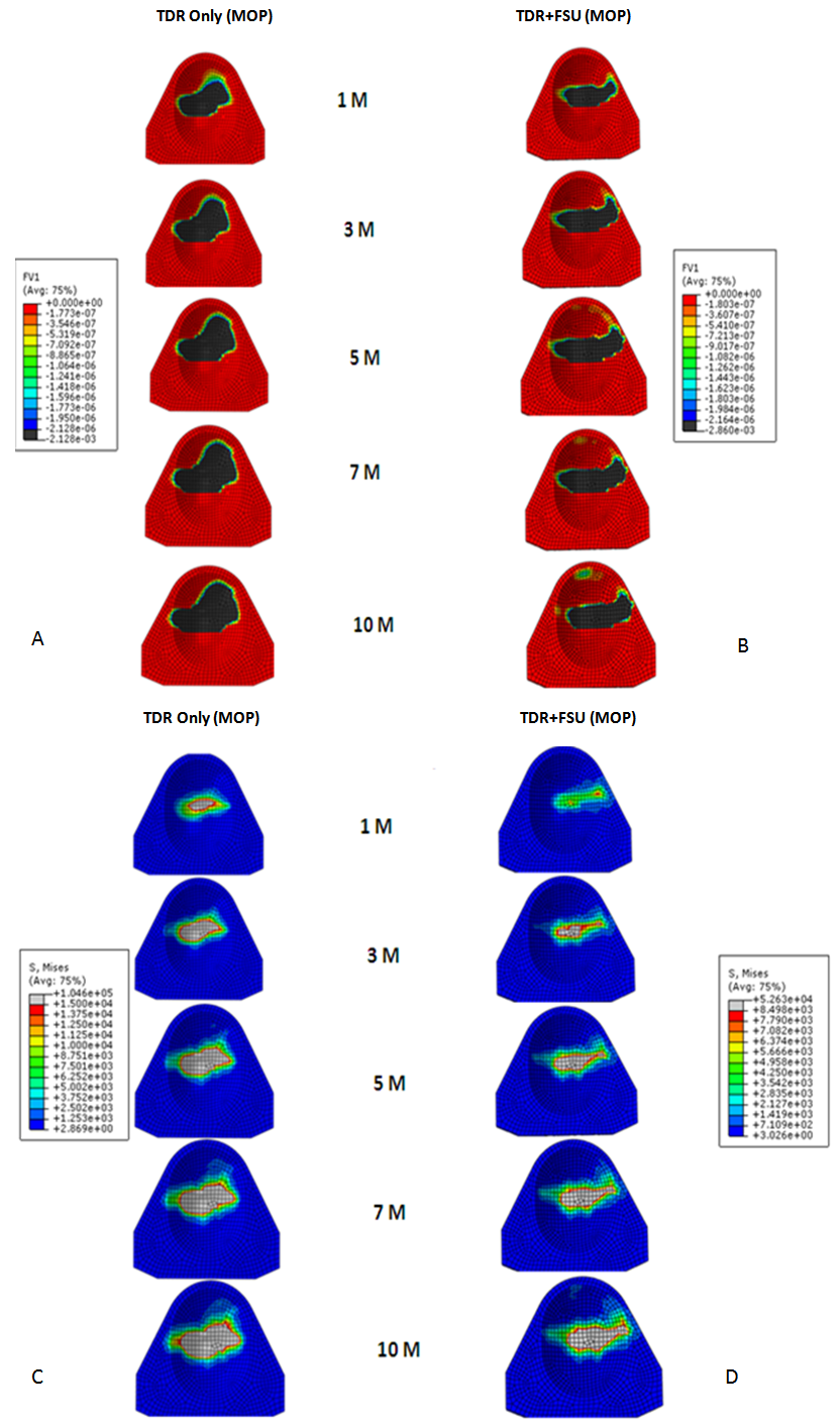 | Figure 3. Linear wear patterns (A&B) and stress patterns (C&D) for TDR only and TDR+FSU simulation for 1,3,5,7 and 10 million cycles |
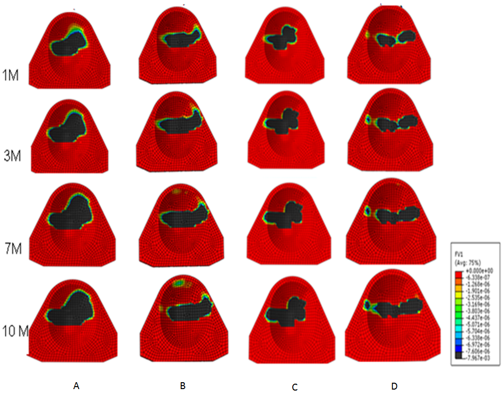 | Figure 4. Linear wear contour for A. TDR Only (MOP), B. TDR+FSU (MOP), C.TDR Only (MOM) and D. TDR+FSU (MOM) 1,3,7 and 10 million cycles |
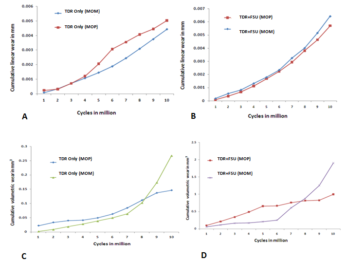 | Figure 5. A. Cumulative linear wear rate for TDR Only (MOM) vs.TDR Only (MOP) upto 10 million cycles B. Cumulative linear wear rate for TDR+FSU (MOP) vs.TDR+FSU (MOM) upto 10 million cycles C.Cumulative volumetric wear rate for TDR Only (MOP) vs.TDR Only (MOM) upto 10 million cycles D.Cumulative volumetric wear rate for TDR+FSU (MOP) vs.TDR+FSU (MOM) upto 10 million cycles |
4. Discussion
- In response to limitations of previously reported predictive wear models of the TDR alone, a concept was developed for studying wear characteristics using an artificial disc placed within a ligamentous FSU[11]. Unlike wear simulator experiments and TDR-only predictive models, the proposed approach allowed the study of the effects of spinal structures on wear. In the present paper, this model was further extended to investigate the effect of material couple on the wear characteristics of TDR.Before interpreting predictive wear data, it is essential to establish the model’s validity and clinical relevance. This can be achieved in several steps. Validation of kinematic results from both intact and implanted models are reported elsewhere[13]. The same model was used for wear simulation in this study. It has already been proven in our earlier paper that the TDR-only wear model (polymeric ball on socket) predictions are in agreement with several published studies[14]. For example, the volumetric wear reported was in agreement with the wear simulation data of Prodisc-C, as reported by the device-company[14] . The wear trend reported by Rawlinson et al.[8] for the lumbar artificial disc was also similar to the previous model’s predictions. The predicted wear pattern of the that study, marked by maximum wear at the outer periphery (circumferential wear pattern) for the TDR-only model, corresponds with the findings of de Jongh et al.[15]. These give credibility to the current model which is t derived from the previously validated model.In a wear simulator study conducted by Bushelow et al.[16] it was presented that in the case of lumbar artificial discs metal wear was 3-4 times less than polymeric wear rate. This is contrary to the 10-50 times reduction shown in total hip implants. It should be noted however, that the comparison was derived between ball on socket versus ball on trough design. The difference may be due to MOM vs MOP and the differences in the design of THA. Along similar lines we compared the cervical implants - metal on metal (ball on trough) test case with a metal on poly (ball on socket) design[14]. Metal on metal combination led to a decrease in volumetric wear by ~64 times, using the ISO test protocol. So the findings are in line with Buschelow’s comparative study. This comparison provides further validation of our predictive model; results being qualitative in agreement.When the artificial discs were simulated in a FSU, however, the MOM combination showed a volumetric wear of 1.91 mm3 which was greater than MOP predicted wear of 0.95 mm3, quite contrary to common sense understanding that wear rates in MOM are smaller than MOP combinations. This also reconfirms our previous finding that FE simulation of wear in implants should be conducted in a ligamentous spinal model instead of standalone test cases. Thus, based on our current findings we could rather establish that metal on metal could have been a better combination for THA, but not for TDA. A further validation of our work was provided by a study on similar device reported by Kurtz et al.[17]. Here the wear maps are quite similar to the wear contour that has been predicted by our FE models (Figure 6).
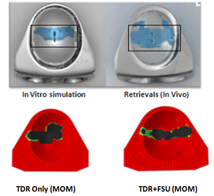 | Figure 6. Comparison of wear contours as seen in simulations and retrievals with FE models |
5. Conclusions
- Wear is a very complex multifactorial problem. Although standardized lab testing procedures are designed to replicate in vivo conditions, successful in vitro tests do not always translate to better physiological performance. Furthermore, it has also been reported in literature that retrievals often reflect failure modes which are not observed during bench top simulations. Massive efforts have been invested into wear reduction by design optimizations, implantation techniques as well as formulation of newer materials[3]. In regards to hip replacements, metal on metal articulations were favored in comparison to metal on poly combinations primarily because of its superior wear resistance properties [12]. Thus such a bearing combination was also designed for the artificial disc with the hope of it being a promising material choice. Recently, news of failed metallic hips has become a major concern for the research community. This has lead to a common bias against metal-on-metal hips. This would mean forgoing an entire class of product rather than a single implant or a company[18]. Even though the superiority of MOM is evident during in-vitro tests, this does not necessarily hold true in an in-vivo setting. In addition, ball-on-trough design could be much better suited for MOM than MOP. Furthermore, it is much too simplistic to look at only the material couple or the design; it is important to consider the affect of implant location and possible interactions with the surrounding anatomy /physiology which could lead to different wear outcomes. We are currently pursuing additional studies along these lines. Since total disc arthroplasty is still a newer technology, news of failed metal discs do not emerge quite often. This is primarily because there is a very disc implants so it may be a bit premature to judge them based on so few retrievals. Missing from the literature are long term retrievals which would assist the determination of more clinically relevant testing methodology. Based on our results we are able to conclude that though material properties are important but design factors, as well as soft tissue, play an equal role in determination of the wear outcomes in an implant.