-
Paper Information
- Next Paper
- Paper Submission
-
Journal Information
- About This Journal
- Editorial Board
- Current Issue
- Archive
- Author Guidelines
- Contact Us
International Journal of Mechanics and Applications
p-ISSN: 2165-9281 e-ISSN: 2165-9303
2013; 3(5A): 1-7
doi:10.5923/s.mechanics.201308.01
Impact of the Processing History on the Wear Performance of a PEEK-on-PEEK Bearing for Cervical Total Disc Replacement
 Abstract
 Reference
 Full-Text PDF
 Full-text HTML
Markus Kraft
Innovation/Materials & Surfaces, DePuy-Synthes, CH-4528 Zuchwil, Switzerland
Correspondence to: Markus Kraft, Innovation/Materials & Surfaces, DePuy-Synthes, CH-4528 Zuchwil, Switzerland.
| Email: |  |
Copyright © 2012 Scientific & Academic Publishing. All Rights Reserved.
In the present study the wear performance of an all PEEK ball-and-socket concept for cervical total disc replacement (TDR) was assessed by in vitro wear tests. The study focused on the effect of different processing histories - in particular milling versus injection molding - on the wear performance. The bearing surfaces were assessed and the retained wear particles were analyzed for their size and morphology. The obtained wear rates for milled parts and molded parts were found to be similar. Annealing of the molded parts did not alter the wear behaviour significantly. All investgated bearing surfaces showed deterioration with severe signs of wear damage. The study revealed that - independent of the processing history - an all PEEK cervical TDR concept does not seem to offer substantial benefits in terms of wear rates if compared to the well established solutions based on UHMWPE-on-CoCr. Therefore, the use of PEEK as a bearing material for cervical TDR must be critically reviewed.
Keywords: Cervical Spine, Total Disc Replacement, Wear Simulation, PEEK, PEEK-on-PEEK Articulation, Wear Particles, Processing History
Cite this paper: Markus Kraft, Impact of the Processing History on the Wear Performance of a PEEK-on-PEEK Bearing for Cervical Total Disc Replacement, International Journal of Mechanics and Applications, Vol. 3 No. A, 2013, pp. 1-7. doi: 10.5923/s.mechanics.201308.01.
Article Outline
1. Introduction
- Since the first implantation of the Charité® disc prosthesis in 1984[1] total disc replacement (TDR) has gained increased attention as an alternative to the fusion of adjacent vertebrae of the spine. The first generation TDRs were mainly based on the conventional materials for joint arthroplasty like UHMWPE-on-CoCr or CoCr-on-CoCr. Throughout the last two decades many different articulation concepts and material combinations have been studied as possible new articulation solutions for TDRs. As it is not leading to artefacts in CT or MRI, and as it features excellent properties as a structural implant material, PEEK has been proposed as a possible candidate material for an all polymer-on-polymer TDR.The first wear test results for a PEEK-on-PEEK bearing device were published by Schwenke[2] and Wimmer[3]. They used customized test protocols which were in part derived from the load parameters as defined in the ISO 18192-1 standard and which were intended to mimic the load and motion conditions of a nucleus replacement device for the lumbar spine. An assessment of the bearing surfaces showed evidence of highly polished areas, mild burnishing and light surface scratches[3]. The same group of researchers investigated the wear performance of a PEEK-on-PEEK cervical TDR[4][5]. They performed in vitro wear tests following the ASTM F2423 standard as well as the ISO 18192-1 standard. The documented wear rates compared well with other cervical arthroplasty devices in clinical use at the time. The bearing surfaces as documented in[5] showed a highly polished condition except for a sample which was tested in a modified test medium. At about the same time Grupp et al.[6] published simulator wear data for PEEK-on-PEEK cervical TDRs with less favorable results: they found much higher wear rates and observed pronounced multi-directional wear tracks with evidence of pitting and delamination. The results by Grupp et al. have been confirmed by Xin et al.[7] and Kraft et al.[8][9] who reported comparably high wear rates combined with a severe surface deterioration of the bearing surfaces[8][9]. The present study attempted to determine whether the manufacturing process of the implants influenced the wear performance of a cervical TDR based on a PEEK ball-and-socket design. Following wear simulator testing the bearing surfaces were further assessed in order to characterize the surface deterioration induced by the wear process. Finally wear particles were analyzed considering particle size distribution and particle shape.
2. Materials & Methods
- The geometry of the test samples was based on a ball-and-socket design with an articulation radius of approximately 7.5 mm. In order to assess the influence of the processing history on the wear performance the following three sample groups were prepared for testing: Group 1 (milled):milling from PEEK Optima LT1 barsGroup 2 (molded & annealed):injection molding from PEEK Optima LT3 pellets, subsequent annealing at 200°C for 4 hours in airGroup 3 (as molded):injection molding from PEEK Optima LT3 pellets
|
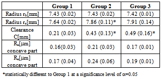
 The articulation radii rs of the concave parts (socket) showed some variation between the groups. The clearance values C = rs-rb for the molded parts were approximately twice the clearance values of the milled parts. The surface roughness Ra (arithmetic mean roughness, cut off length 0.8 mm) was statistically not different for all groups. As illustrated in Figure 1, the surface structures of untested samples depended on the processing history: Within Group 1 (milled) the marks from the cutting process were clearly visible whereas within the Groups 2 & 3 (molded) the surfaces corresponded with the structure of the surfaces of the molds. Prior to testing, all samples were gamma irradiated in air (approximate dose of 22 kGy). The PEEK samples were pre-soaked in demineralized water at ambient temperature for 28 days. The wear tests were performed on an EndoLab® servo-hydraulic wear simulator (further details in[9]) in order to mimic coupled, multi-directional spinal motion around the moving axes x, y, and z. In Figure 2 the test set-up and the sample orientation relative to the moving axes x, y, and z are illustrated. The input parameters for angular displacements per moving axis and the load parameters for the dynamic load FN acting along the z-axis were taken from the definitions for cervical prostheses as per ISO standard 18192-1, section 6.1. For all wear tests a frequency of 2 Hz was applied. The tests were performed at 37°C (±2°C) in a test medium consisting of newborn calf serum (protein concentration of 30 g/l), 20 mmol/l EDTA (ethylene diamine tetraacetic acid) to bind calcium phosphate, and an agent
 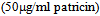 to retard degradation of the test medium by microorganisms (refer to ISO standard 18192-1, 1st edition 2008). The test medium was replaced every 0.5 million cycles (Mc) and retained for the isolation and analysis of wear particles. The amount of wear was determined by weight loss measurements of the specimens after 0.5 Mc, after 1 Mc, and subsequently after each interval of 1 Mc.
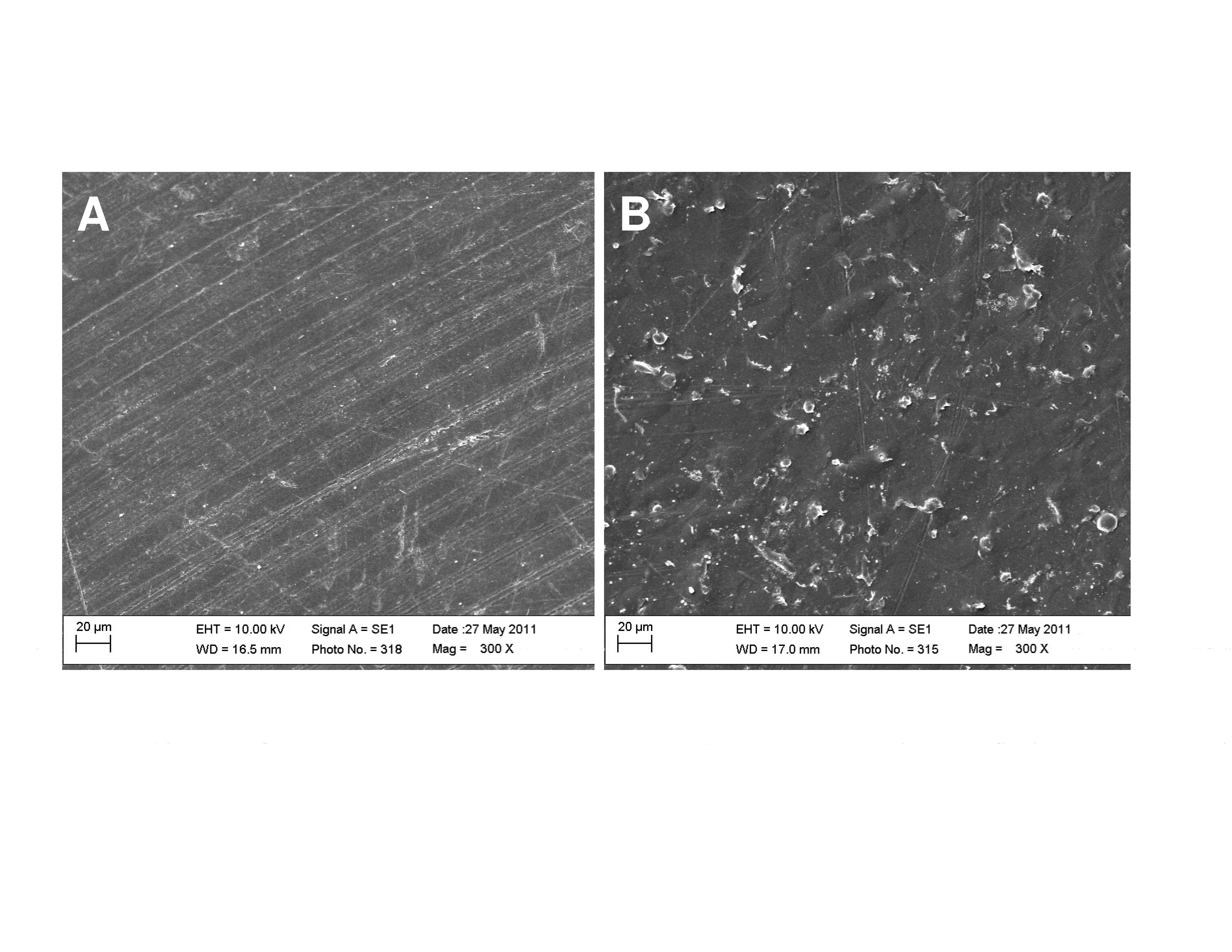 | Figure 1. Surface structure of (A) Group 1 (milled) and (B) of Groups 2 & 3 (molded), SEM images |
 | Figure 2. Sketch of the test set-up showing the sample orientation within the sample fixtures, the moving axes x, y, and z, as well as the load FN acting along the z-axis |
 polycarbonate filter. The filters with the retained wear particles were gold sputtered and examined by SEM at a magnification of 5000x. For each condition, at least 100 particles were analyzed (method from[11]). Equivalent circle diameters (ECD) and shape factors were calculated following ASTM standard F1877-5.
3. Results & Discussion
3.1. Wear Rates
- In Figure 3 the mean gravimetric wear for the Groups 1 to 3 (n=2 for each group) is shown as a function of wear cycles. The wear data for Group 1 (milled) showed in an initial phase between 0 and approximately 3 Mc, a high wear rate of 5.09 mg/Mc and in a second phase starting at 4 Mc up to 10 Mc, a markedly reduced wear rate of 1.44 mg/Mc. For Groups 2 and 3 (molded samples, n=2), during the short run in period over the first 0.5 Mc, very low wear was obtained. This was followed by a distinct wear increase reaching wear rate levels of 4.39 mg/Mc for Group 2 (molded & annealed, n=2) and 4.27 mg/Mc for Group 3 (as molded, n=2). The reported wear rates were obtained by linear regression and are displayed in Figure 3 for Groups 1 and 3. Since the wear rates for the first 4 to 5 Mc were comparable between the 3 groups and since the molded samples did not show evidence of more favorable wear behavior compared to the milled samples, the wear tests for Groups 2 and 3 were not continued beyond 5 Mc.
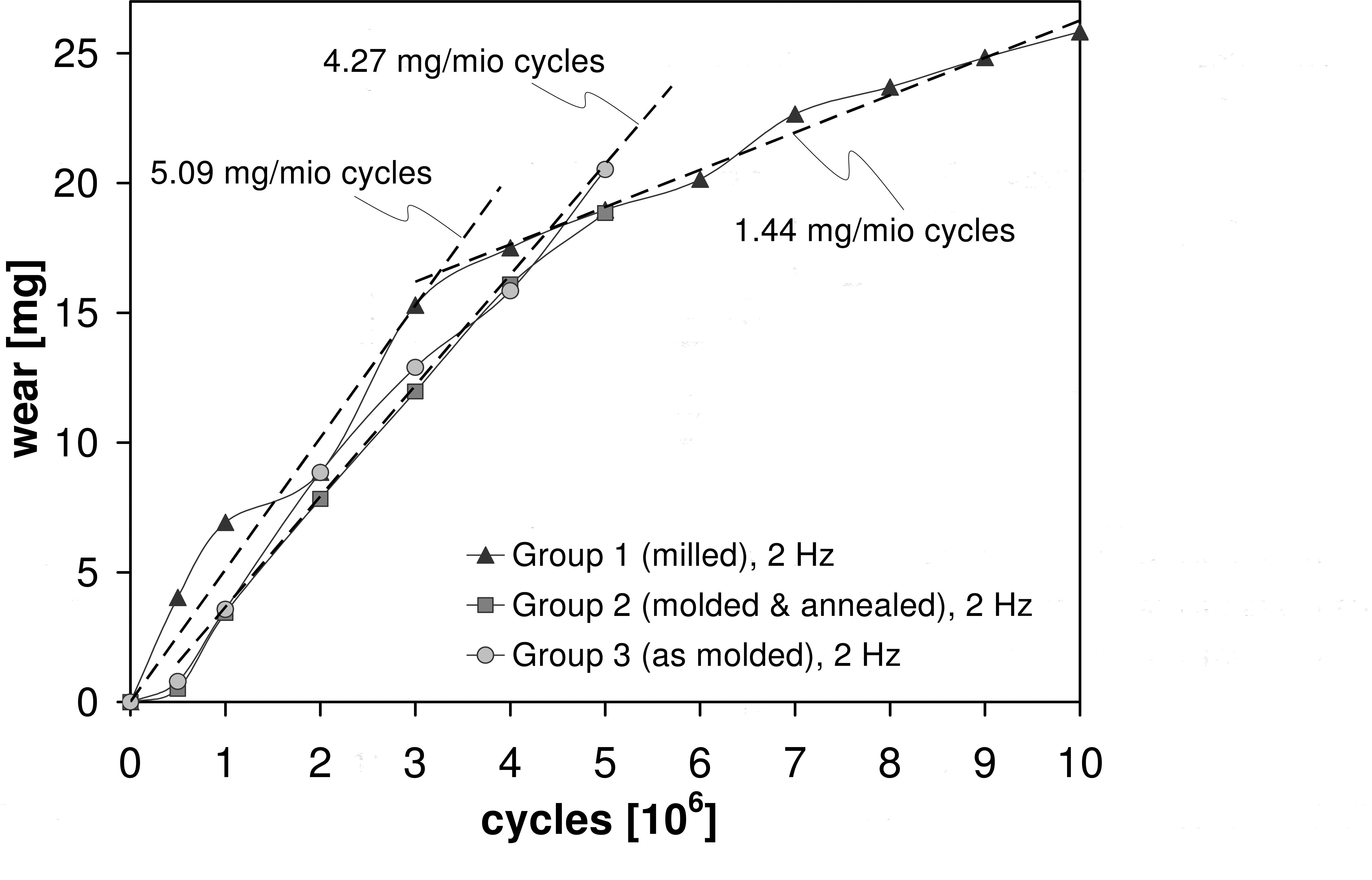 | Figure 3. Wear plot for Groups 1 to 3 |
3.2. Influence of Processing History on Wear Rates
- The main aim of the present study was to evaluate the influence of the processing history on the wear performance of a PEEK-on-PEEK cervical TDR. Milled parts are usually made from extruded and annealed bar stock material. Extrusion grade PEEK is characterized by a high molecular weight (Mw=115’000 daltons for this study). In order to allow for good mold filling properties, injection grade PEEK features a lower viscosity that is usually achieved by a lower molecular weight ( Mw=83’000 daltons for this study). For injection molded samples the hot melt cools down immediately near the mold walls while the central zones are subject to longer solidification times. This potentially leads to a variation in crystallinity, and an inhomogeneous microstructure within the molded part. Annealing (as done for Group 2) is a common way to reduce such inhomogeneities.Correspondingly, the three groups tested in the current study represent three relevant states of PEEK implant material in terms of raw material type and processing history. It is well known that the mentioned differences like overall morphology, degree of crystallinity, or mean crystallite size may impact wear behavior. In literature[17][18] the dependence of PEEK wear from molecular weight, degree of crystallinity, and molecular orientation has been described, however only for PEEK sliding against steel. The wear tests of the current study allowed the comparison of the wear rates of the three sample groups with different processing histories for the initial wear test phase covering 5 Mc. The obtained wear rates were in the same order of magnitude for all groups ranging from 4.27 to 5.09 mg/Mc, with 14% to 16% lower wear rates for molded versus milled samples. As a conclusion, the current study showed that within the explored range of sample characteristics and wear simulation parameters, the wear rates of milled and molded samples were similar and the annealing of molded samples did not have a considerable effect on the wear behaviour.
3.3. Bearing Surface Topography
- In Figures 4 optical microscope images (2.7x magnification) of the bearing surfaces of representative samples at different stages of the wear tests are shown. The bearing surfaces of Group 1 (milled) showed signs of wear at 0.5 Mc with distinct oval shaped wear traces which were consistent with the multi directional motion pattern of the wear test. At 3 Mc the images indicated a dramatic increase in wear damage with similar oval shaped wear traces but more pro-nounced groove-like appearance. With increasing number of wear cycles (5 & 10 Mc) the appearance of the worn bearing surfaces remained unchanged. For Group 2 (molded & annealed) the overall picture was similar to Group 1 except for reduced oval shaped scratches at 0.5 Mc which coincided with the low amount of wear for this end point (see Figure 3).In order to further characterize the bearing surfaces after test completion, SEM images were taken (refer to Figure 5). Qualitatively Group 1 (milled), subject to 10 Mc and the Group 2 (molded & annealed), subject to 5 Mc exhibited the same type of surface damage. In both cases, severe signs of wear with distinct curved wear tracks were found onto the bearing surfaces. A second type of damage was observed at exposed areas predominantly along the rims which were formed by the wear tracks. In these locations the material was subject to surface fissures and break-out of material, leaving pit holes of up to
 in diameter. A third phenomenon was captured e. g. in Figure 5(b) where abraded particles were plastically deformed to a flake like structure and compressed onto the bearing surface. From literature it is well known that PEEK-on-PEEK wear is attributed to the combined action of micro-cutting, fatigue delamination, and plastic flow effects ([19],[20]). The wear pattern at different stages during the wear tests as documented in Figures 5 support the hypothesis of a progressive increase of surface roughening in the initial 0.5 to 1 Mc possibly caused by asperite contacts. At a later stage all tested samples show wear pattern of similar severity. The observed wear pattern in this study conform well to observations reported in[6] and similarly in[7]. On the other hand, the deterioration of the bearing surfaces are not in line with the concept of a self-mating behavior for a cervical all PEEK articulation as postulated in[4] or[5]. Under the applied conditions wear testing of a PEEK-on-PEEK bearing concept for a cervical TDR led to an unfavorable wear situation with severe damage of the bearing surfaces for all sample groups, hence independent of the processing history of the respective PEEK parts.
 | Figure 4. Appearance of concave & convex bearing surfaces as a function of wear cycles |
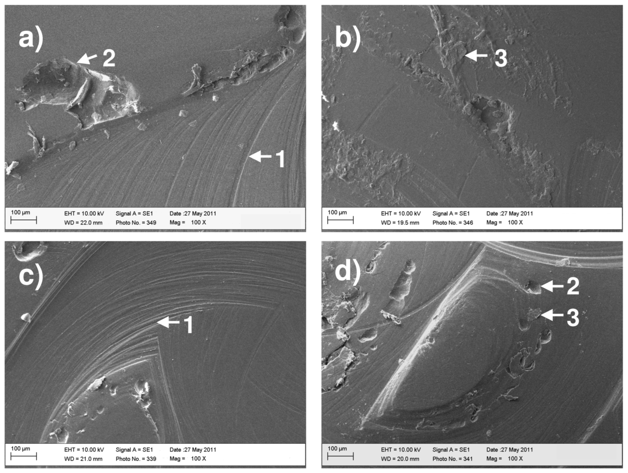 | Figure 5. SEM images of bearing surfaces: (a) Group 1 at 10 Mc, concave; (b) Group 1 at 10 Mc, convex; (c) Group 2 at 5 Mc, concave; (d) Group 2 at 5 Mc, convex; wear signs: (1) wear tracks, (2) break-outs, (3) flake like structures |
3.4. Wear Particle Analysis
- For selected test intervals the distribution of the equivalent circle diameters (ECD) of the wear particles were compared (refer to Figure 6). As a
 filter was used, particles smaller than
  were not retained and were therefore.not captured. The ECD values ranged between
  and
and  The ECD distribution of Group 1 was shifted to larger values compared to ECD distributions for Groups 2 & 3.
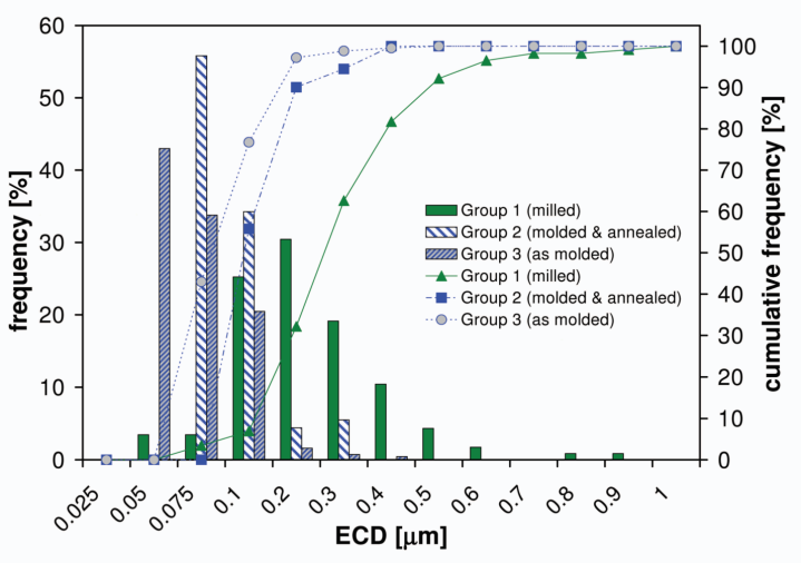 | Figure 6. Distribution of the ECD for Groups 1, 2, and 3, exemplary for the test interval 4.5 to 5 Mc |
|
|
 In contrast in[4] a mean ECD value of
  has been found which is by far larger than the mean ECD values found in this study. Previous wear simulator studies with UHMWPE-on-CoCr couples for cervical TDR revealed polyethylene wear particles with a size range between 0.05 and
  and a mean ECD between 0.17 and
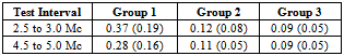
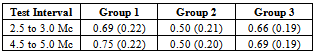
  As a conclusion the majority of the cited studies reported similar particle sizes in the submicron range for both PEEK and UHMWPE.In Table 3 the mean shape factors for the analyzed test intervals are listed. The mean shape factors were approximately 0.5 for Group 2 (molded & annealed). For Groups 1 & 3 the respective values ranged from 0.66 to 0.75. When comparing to literature the values for the shape factor are in the same order of magnitude as respective values reported in[6] ( mean shape factor of 0.5) and[4] (mean shape factor of 0.66).
4. Conclusions
- The wear behavior of milled and molded PEEK samples with and without annealing has been investigated. The results suggest that the wear rates for milled parts and molded parts are similar. An annealing of the molded parts does not seem to alter the wear behavior. An all PEEK cervical TDR concept does not seem to offer substantial benefits in terms of wear rates if compared to the well established solutions based on UHMWPE-on-CoCr. The high wear rates correlate with a severe deterioration of the bearing surfaces. These findings indicate that independent of the manufacturing method the use of PEEK for cervical TDR might be subject to severe long term damage of the bearing surfaces. Similar to the findings stated in[21] the present study suggests that an all PEEK bearing solution for cervical TDRs bears considerable tribological risks. Considering the large wear rates in the initial test phase and considering the lack of long term clinical data on PEEK wear in cervical arthroplasty, a much broader understanding on the interrelation between wear test parameters, design parameters, and the wear behavior of a PEEK-on-PEEK bearing is deemed necessary.
ACKNOWLEDGEMENTS
- The author wishes to thank Y. Bisselbach (DePuy-Synthes) for his help in obtaining the SEM micrographs and M. Hintner (Endolab GmbH) for his assistance with the wear tests. Special thanks to M. Bushelow (DePuy Synthes) for interesting discussions as well as to E. Minnock (DePuy Synthes) for a critical review of the manuscript.