-
Paper Information
- Previous Paper
- Paper Submission
-
Journal Information
- About This Journal
- Editorial Board
- Current Issue
- Archive
- Author Guidelines
- Contact Us
American Journal of Materials Science
p-ISSN: 2162-9382 e-ISSN: 2162-8424
2015; 5(3A): 55-61
doi:10.5923/s.materials.201502.09
Dielectric Behavior of P(VDF-TrFE) /PZT Nanocomposites Films Doped with Multi-walled Carbon Nanotubes (MWCNT)
 Abstract
 Reference
 Full-Text PDF
 Full-text HTML
Ashok K. Batra1, Matthew E. Edwards1, 2, Almuatasim Alomari1, Adnan Elkhaldy1
1Department of Physics, Chemistry and Mathematics, Alabama A&M University, Normal, USA
2Institute of Higher Science Education Advancements and Research (IHSEAAR), New Market, USA
Correspondence to: Matthew E. Edwards, Department of Physics, Chemistry and Mathematics, Alabama A&M University, Normal, USA.
| Email: |  |
Copyright © 2015 Scientific & Academic Publishing. All Rights Reserved.
In this study, we have demonstrated a comparison of the dielectric and electric properties achieved in P(VDF-TrFE)/ PZT and P(VDF-TrFE) doped with multi-walled carbon nanotubes (MWCNT). PZT/P(VDF-TrFE) composites (0–3 type) doped with MWCNT were prepared and fabricated by the conventional cost effective solution casting technique. The dielectric and electric transport properties of composite films have been investigated. The dielectric parameters of the composite films were calculated by the measurement of capacitance and dielectric loss. The dielectric constants, ε' and ε'', each a function of temperature and frequency have been determined. The results showed an increase in both quantities with increasing frequency and temperature. From the Cole-Cole plot, the optical dielectric constant, static dielectric constant, spreading factor α, and the molecular relaxation time were calculated.
Keywords: Dielectrics, Composites, PZT/P(VDF-TrFE), Multi-walled carbon nanotubes
Cite this paper: Ashok K. Batra, Matthew E. Edwards, Almuatasim Alomari, Adnan Elkhaldy, Dielectric Behavior of P(VDF-TrFE) /PZT Nanocomposites Films Doped with Multi-walled Carbon Nanotubes (MWCNT), American Journal of Materials Science, Vol. 5 No. 3A, 2015, pp. 55-61. doi: 10.5923/s.materials.201502.09.
Article Outline
1. Introduction
- Piezoelectric materials have been used in recent years in many applications, including dynamic strain gauges, transducers and vibration sensors for alarms, switches, speakers, and contact microphones [1-9]. PVDF and PZT are considered two of the most important piezoelectric materials. This status is due to the fact that the piezoelectric coefficient of PVDF and its copolymers such as [P(VDF-TrFE)] is ten times larger than any other polymer. It is also a material of high flexibility, high toughness, and can be readily formed into a thin film profile. Moreover, PZT is a ferroelectric ceramic material with characteristics including high dielectric constant, high coupling, high charge sensitivity, high density with a fine grain structure, a high Curie point, and a clean noise-free frequency response. Carbon nanotubes (CNTs) have been widely used with ceramic-polymer composites because of their large aspect ratio and high surface area. Furthermore, Ferroelectric lead zirconate and barium titanate are the candidate materials for high-k capacitance.These materials require high temperature processing that is not compatible for embedding the capacitors in the printed circuit board.Several researchers, including the authors of this paper, have investigated pyroelectric, piezoelectric, and other physical properties of P(VDF-TrFE) composite (0-3 type) films fabricated by the low temperature solution casting method [9]. Mechanical, ferroelectric, and dielectric properties of PZT/PVDF 0–3 composites have been studied for electrical and mechanical properties of PZT/PVDF 0–3 composites, and the results have shown that composites with higher ceramic content had higher dielectric constant and dielectric loss tangent. Effective relative permittivity, dielectric loss factor, piezoelectric charge coefficient, and Young’s modulus of PZT/PVDF have been studied experimentally, and the results have been shown to be well fitted theoretically. Effects on electrical and structural properties of PZT-PVDF composites have been examined by PVDF phase formation, and its Influence on electrical and structural properties of PZT-PVDF Composites, the piezoelectric coefficient and remnant polarization, was found to decrease with a decrease in ceramic particle size. PZT/PVDF composites (0–3 type) doped with carbon nanotubes were prepared and studied by Guan et al (2013). PZT/PVDF composites doped with carbon nanotubes were prepared by adding carbon nanotubes to PZT/PVDF composites (0-3 type) to enhance the dielectric constant.PZT/[P(VDF-TrFE)] matrices were prepared using the solution casting method: Poling studies of PZT/PVDF-TrFE composites, screen-printing on indium–tin-oxide (ITO)-coated glass substrates, structural and functional properties of screen-printed on piezoelectric and pyroelectric films have been investigated. In 2009, Batra et al. investigated pyroelectric polymer composites: silver nano-particles embedded in P(VDF-TrFE)/Lithium tantanate, and indicated an enhancement in pyroelectric performance as compared with virgin P(VDF-TrFE)/LT composites [11].According to the literature, only few works were concerned about studying P(VDF-TrFE)/PZT doped with multi-walled carbon nanotubes (MWCNT) with their dielectric behaviors from the viewpoint of their use in embedded capacitors. These electric phenomena are essential to understand the mechanical and poling behavior of composites. For example, the accumulation and de-trapping of electric charges resulting from mechanical or thermal loads can be responsible for the failure of these materials. Different composites of PZT, BT, and BST with various types of polymers such as PVDF, PVC, PVA, and copolymers have been widely studied and reported in the literature [5]. However, in this paper we demonstrate dielectric behavior of P(VDF-TrFE)/PZT composites doped in MWCNT of thick films. In the present paper, synthetic P(VDF-TrFE)/PZT composites doped in MWCNT for active functional components of the thick film composite and conductive silver paint for the electrodes have been investigated for dielectric and AC conductivity in a large domain of temperature and frequency. The composite P(VDF-TrFE)/PZT (modified lead zirconate titanate nano-particles) doped in MWCNT films were fabricated by an efficient conventional and cost effective brush coating on flexible copper substrate that acted as one of the electrodes as well.
2. Experimental and Methods
- The 0-3 connectivity composite films were fabricated using the solution casting technique. The first step in the preparation of the Pmix was to mix a suitable amount of modified nano-PZT (lead zirconate titanate) powder (about 100 nm particle size) in P(VDF-TrFE) at room temperature. A requisite amount of MWCNT solution was then added to form nPMix, and this mixture was ultrasonically agitated/mechanically stirred, for several hours, to break-up the agglomerates and disperse the MWCNT uniformly in the Pmix. The length and diameter of multi-walled carbon nanotubes were 10 µm and 9 - 12 nm (average) respectively. The obtained nPMix composite solution was kept in a suitable container for the solvent to evaporate. The films were annealed for 2 - 3 hours in the air at 110˚C. A full-face silver electrode was deposited on the film (front and back faces), then the film was cut into 10 mm × 10 mm sized element for testing. The electrode samples were poled at 60˚C using 9 kV/cm for 2 hours. After the poling process, the samples were short circuited and annealed at 50˚C for 2 hours. The flowchart of the fabrication processes is depicted in Figure 1.
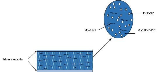 | Figure 1. Representation of P(VDF-TrFE)/ PZT with MWCNT film |
|
 | (1) |
 | (2) |
 | (3) |
3. Results and Discussion
- FTIR spectra of the samples show that crystallization of the polymer occurs in the ferroelectric phase, with Fig. 2 showing the presence of the absorption band at 880, 1169, and 1397 cm-1, characteristic of the ferroelectric phase of the polymer.
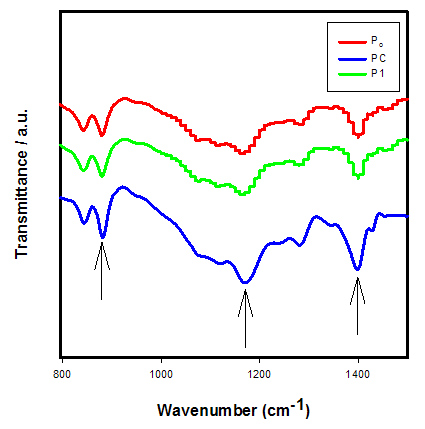 | Figure 2. Transmission spectra of Po, P1 and PC films at room temperature |
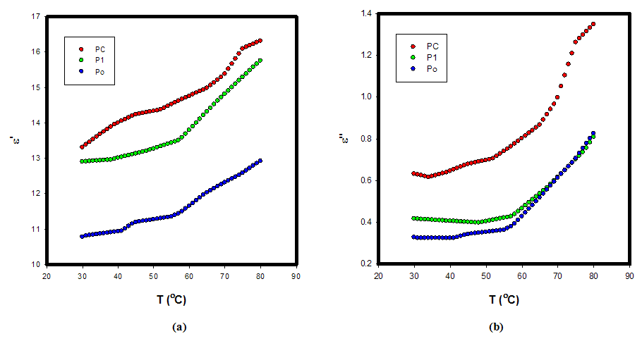 | Figure 3. (a) Real part of dielectric constant (ε') (b) imaginary part of dielectric constant (ε'') vs. temperature of P(VDF-TrFE)/PZT film at 10 kHz |
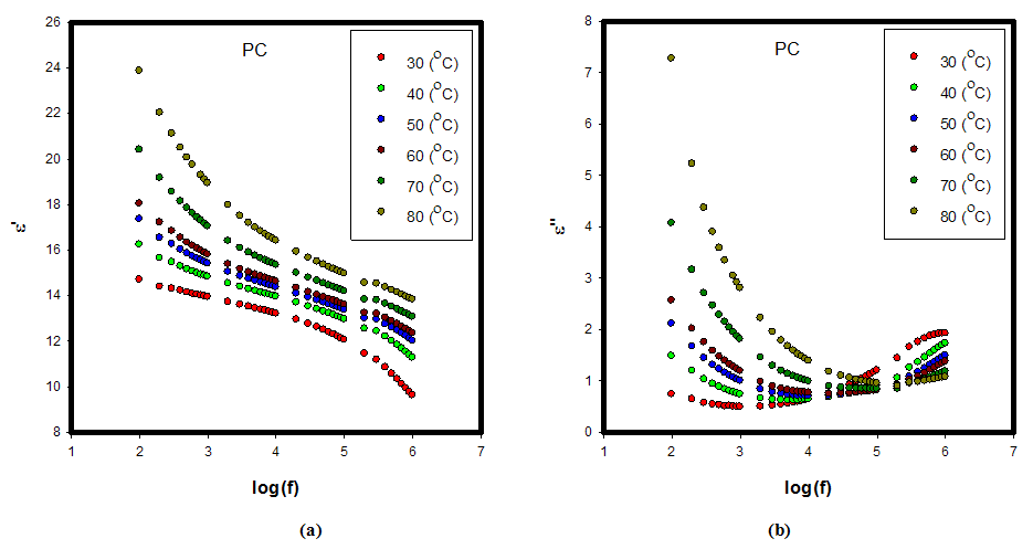 | Figure 4. (a) Real part of dielectric constant (ε') (b) Imaginary part of dielectric constant (ε'') vs. frequency of P(VDF-TrFE)/PZT with MWCNT film at different temperature |
 1/T as is shown in Fig. 4. The results show that with increasing frequencies, for each sample the activation energies Ea slightly decrease e. g., for sample P1 energy Ea decreases from 0.268 eV for 1 kHz to -0.117 eV for 1 MHz (see Fig. 5.). Also, it has been observed that the calculated Ea of the samples is negative at 100 kHz and 1 MHz, which indicates that the electrons are already activated, and that at 1 kHz and 10 kHz, Ea is positive, which indicates that a large number of electrons are present at the interface of samples. Therefore, interfacial polarization is easily realized. However, the positive activation energy implies that the movement of electrons is restricted in the samples at 1 kHz and 10 kHz as we increase the frequency, while electrons are released.
 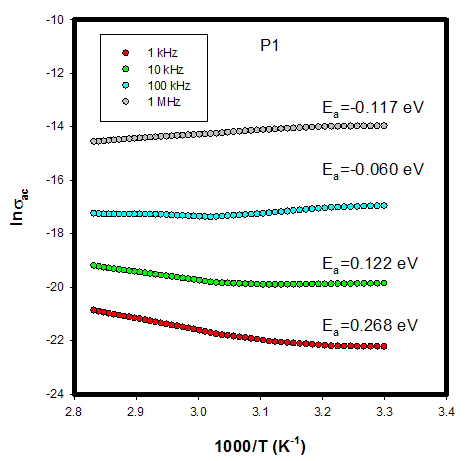 | Figure 5. Temperature dependence of the AC conductivity for P(VDF-TrFE)/PZT film (P1) at different frequencies |
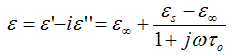 | (4) |
 : is the low frequency of
  (the static dielectric constant),
  is the high frequency of
  the optical dielectric constant, and
  is the applied angular frequency
  .Cole and Cole (Graca et al., 2003) suggested that the complex dielectric constant of liquids and solids might follow the empirical relation of the form:
 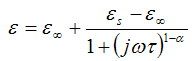 | (5) |
 is the average relaxation time and α is the spreading factor of the actual relaxation time
  (0 < α < 1). When α equals zero, the dielectric has only one relaxation time.The Cole-Cole analysis can be used to obtain the relaxation time of the relaxation process. The average relaxation time may be calculated from the relation:
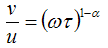 | (6) |
 is the distance on the Cole-Cole plot between εs and an experimental point, and
  is the distance between the experimental point and ε∞.Fig. 6 shows the Cole-Cole plot of the real part of the dielectric constant ε' (dielectric constant, real component) and dielectric loss ε'' (dielectric constant, imaginary component) of sample PC at various temperatures. It is clear from the plot that the relaxation process differs from the Debye relaxation process. The center of the circle of which this arc was a part lays below the real axis and the diameter drawn through the center from the ε∞ point made an angle
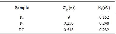
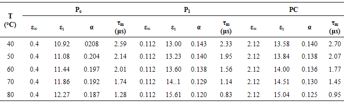
  From the Cole-Cole plot the parameters like the spreading factor α, optical dielectric constant ε∞, static dielectric constant εs, and molecular relaxation time τm are determined and listed in Table 3.
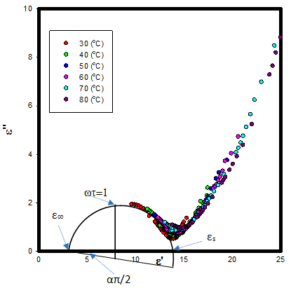 | Figure 6. Cole-Cole plots for PZT/P(VDF-TrFE) composites (0–3 type) doped with MWCNT at various temperatures |
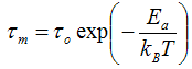 | (7) |
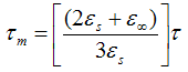 | (8) |
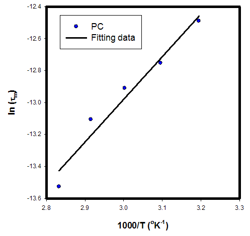 | Figure 7. ln (τm) vs.1000/T for sample PC. The solid black line shows the fits to Eq. (8) |
|
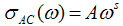 | (9) |
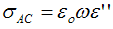
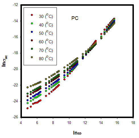 | Figure 8. Frequency dependence of AC Conductivity σAC of PZT/P(VDF-TrFE) composites (0–3 type) doped with MWCNT at various temperatures for PC sample |
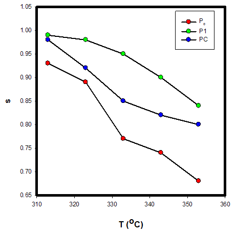 | Figure 9. Temperature dependence of frequency exponent (s) for samples |
 | (10) |
|
4. Conclusions
- The experimental results obtained from our nanocomposite films P(VDF-TrFE)-PZT can be summarized as follows:• Films of P(VDF-TrFE)-PZT have been fabricated using the conventional cost-effective solution casting method. This technique is a very useful and inexpensive process for manufacturing nanocomposite high-k capacitors, sensors, and piezoelectric energy conversion devices because the films can be fabricated with less energy, time, and effort as compared to ceramic and single crystal fabrication. • Films were characterized for their dielectric and electric transport properties as a function of composition, frequency, and temperature. The correlated barrier hopping (C.B.H.) was attributed to that possible conduction mechanism. The increase of dielectric constants at lower frequencies was attributed to space-charge and interfacial polarization.• The dielectric constant of the composite films increased with an increase in modified PZT volume fraction in the composite films. The dielectric constant reached around room temperature 14 at 1kHz for the 10.94 vol % - P(VDF-TrFE) /PZT with MWCNT film, which is larger than the dielectric constant of P(VDF-TrFE) film without PZT nano-particles. Based on the preliminary results obtained, P(VDF-TrFE) /PZT films are attractive for their use in sensing elements and high-k capacitance especially in applications where flexible and curved-surface based sensors are required. Further work is in progress to fabricate films with higher concentration of active ceramic to ascertain the ferroelectric, piezoelectric, and pyroelectric properties including the mechanisms for enhancement of properties of P(VDF-TrFE)/PZT composite films.
ACKNOWLEDGEMENTS
- The authors gratefully acknowledge the support for this research work through the National Science Foundation grant # EPSCoR R-II-3 (EPS-1158862), Evans Allen Grant of USDA, the HBCU-UP and APEX grants. The authors extend special appreciation to Professor Chance Glenn, Dean, college of Engineering, Technology and Physical Sciences, and Dr. Mohan Aggarwal for their support and keen interest in the subject, and thanks to Mr. Garland Sharp for fabrication of the sample holders.
References
| [1] | Mailadil T. Sebastian, “Polymer-Ceramic composites of 0-3 connectivity for circuits in electronics a review,” Int. J. Appl. Ceram. Technol. Vol. 7, pp. 415-434, 2010. |
| [2] | X. Guan, Y. Dong, Z. Hui Li, and J. Ou, “PZT/PVDF composites doped with carbon nanotubes,” Sensors and Actuators A: Physical, vol. 194, pp. 228-231, May. 2013 |
| [3] | P. Han, S. Pang, J. Fan, X. Shen, T. Pan “Highly enhanced piezoelectric properties of PZT/PVDF composite by tailoring the ceramic Curie temperature, particle size and volume fraction,” Sensors and Actuators A., vol. 204, pp. 74-78, 2013. |
| [4] | R. C. Buchanan, J. Huang, “Pyroelectric and sensor properties of ferroelectric thin film for energy conversion,” J. Europ. Ceram. Soc. Vol. 19, pp. (147-1471?) 1999. |
| [5] | A. K. Batra, M. D. Aggarwal, M. Edwards, A. S. Bhalla, “Present Status of Polymer: Ceramic Composites for Pyroelectric Infrared Detectors. Ferroelectrics,” vol. 366, pp. 84-121, 2008. |
| [6] | A. K. Batra, M. A. Alim, M. D. Aggarwal, J. R. Currie, “The electrical response of modified Lead Titanate –based Thick films,” Physica B, vol. 404, pp.1905-1911, 2009. |
| [7] | P. Guggilla, A. K. Batra, M. E. Edwards, “Electrical characterization of LiTaO3:P(VDF-TrFE) composites,” J. Materials Science, vol. 44, pp. 5469-5474, 2009. |
| [8] | M. E. Edwards, A. K. Batra, A. K. Chilvery, P. Guggilla, M. Curley, M. D. Aggarwal, “Pyroelectric properties of PVDF: MWCNT nanocomposite film for uncooled infrared detectors,” Materials Sciences and Applications, vol. 3, pp. 851-855, 2012. |
| [9] | M. E. Edwards, A. K. Batra, A. K. Chilvery, P. Guggilla, M. D. Aggarwal, “Characterization of polymeric composite films with MWCNT and Ag nanoparticles,” Infrared Sensors, Devices, and Applications II, SPIE vol. 8512, 2012. |
| [10] | S. Wen, D. L. Chung, “Pyroelectric behavior of cement-based materials,” Cement and Concrete Research, vol. 33, pp. 1675-1679, 2003. |
| [11] | A. K. Batra, J. Corda, P. Guggilla, M. D. Aggarwal, M. E. Edwards, “Dielectric and pyroelectric properties of LiTaO3:P(VDF-TrFE) composite films” SPIE, vol. 7213, 2009 |
| [12] | J. Kumar, S. N. Choudhary, K. Prasad, R. N. Choudhary, “Electrical properties of 0.25Ba(Bi1/2Ta1/2)O3-0.75BaTiO3,” Adv. Mat. Lett. Vol. 5, no. 2, pp. 106-110. 2014. |
| [13] | S. El-Sayed, “Optical properties and dielectric relaxation of polyvinylidene fluoride thin films doped with gadolinium chloride,” Physica B. vol. 4, no. 454, pp. 197-203, 2014. |
| [14] | D. K. Ray, A. K. Himanshu, T. P. Sinha, “Structural and low frequency studies of conducting polymer nanocomposites,” Indian J. Pure Appl. Phys. vol. 45, pp. 692-699, 2007. |
| [15] | M. I. Mohammed, A. S. Abd-rabo, E. Mahmoud, “Conductivity and dielectric behavior of chaleogenide Gex Fex Se100-2x thin films. Egypt,” J. Sol., vol. 25, no. 1, pp. 49-56, 2002. |
| [16] | A. C. Lopes, C. M. Costa, R. Sabater, “Dielectric relaxation, ac conductivity and electric modulus in poly (vinylidene fluoride)/NaY zeolite composites,” Sold State Ionics, vol. 235, pp. 42-50, 2013. |
| [17] | R. Singh, J. Kumar, R. K. Singh, A. Kaur, R. D. P Sinh, N. P. Gupta, “Low frequency ac conduction and dielectric relaxation behavior of solution Grown and uniaxially stretched poly(vinylidene fluoride) films,” Polymer, vol. 47, pp. 5919–5928, 2006. |
| [18] | N. F. Mott, E. A. Davis, Electronic Processes in Non-crystalline Materials, 2nd edition, Oxford University Press Inc, New York, 1979. |
| [19] | A. K. Jonscher, Dielectric Relaxation in Solids, Chelsea Dielectric Press, London, 1983. |
| [20] | S. R. Elliot, “A.C. conduction in amorphous chalcogenide and pnictide semiconductors,” Adv. Phys vol. 36, pp. 135-214, 1987. |
| [21] | N. Vijayakumar, E. Subramanian, P. D. Pathinettam, |
| [22] | “Single/Double Soft-Templates involved synthesis of polyaniline blends: interfacial polymerization and characterization by AC impedance analysis,” Journal of Macromolecular Science, Part B: Physics. Vol. 51, pp. 1617-1636, 2012. |