-
Paper Information
- Next Paper
- Previous Paper
- Paper Submission
-
Journal Information
- About This Journal
- Editorial Board
- Current Issue
- Archive
- Author Guidelines
- Contact Us
American Journal of Materials Science
p-ISSN: 2162-9382 e-ISSN: 2162-8424
2015; 5(3A): 8-15
doi:10.5923/s.materials.201502.02
Ammonia Sensor Based on Polymer-Inorganic Nano-composite Thin Film Upconversion Light Emitter Prepared by Double-Beam Pulsed Laser Deposition
 Abstract
 Reference
 Full-Text PDF
 Full-text HTML
Abdalla M. Darwish1, Simeon Wilson1, Ashley Balckwell1, Keylanta Taylor1, Sergey S. Sarkisov2, Darayas N. Patel3, Brent Koplitz4
1PhysicsDepartment, Dillard University, New Orleans, USA
2SSS Optical Technologies, LLC, Huntsville, USA
3Department of Mathematics & Computer Science, Oakwood University, Huntsville, USA
4Chemistry Department, Tulane University, New Orleans, USA
Correspondence to: Abdalla M. Darwish, PhysicsDepartment, Dillard University, New Orleans, USA.
| Email: |  |
Copyright © 2015 Scientific & Academic Publishing. All Rights Reserved.
The objective of the paper was to demonstrate feasibility of an ammonia sensor using polymer –inorganic nano-composite thin film upconversion light emitters made by the new double-beam pulsed laser deposition method. The existing pulsed laser deposition vacuum chamber was modified to accommodate two laser beams of different wavelengths for the in-situ ablation of two targets: a polymer host poly(methyl methacrylate) mixed with indicator dye Phenol Red and the brilliant rare earth doped upconversion phosphor NaYF4:Yb3+, Er3+. Nano-composite films were deposited on silicon substrates by the proposed method with near-infra-red laser radiation (1064-nm wavelength) ablating the polymer target dissolved in Gamma-butyrolactone together with the indicator dye, and frozen in circulating liquid nitrogen (matrix assisted pulsed laser evaporation – MAPLE), and visible radiation (532 nm) ablating the inorganic target. The deposited nano-composite films retained bright green upconversion fluorescence with a spectral peak at 540 nm attributed to the inorganic phosphor nano-particles pumped with the 980-nm infrared laser diode. The spectrum of the green emission matched the absorption band of the indicator dye exposed to ammonia. When the films were exposed to ammonia, they demonstrated an optical response in the form of the drop of the intensity of green radiation monitored with a silicon photodiode. The sensitivity of the opto-electronic sensor of ammonia based on the nano-composite films was measured to be close 0.4% ammonia in air, and the response time was 5 minutes.
Keywords: Polymer-inorganic nano-composite films, Pulsed laser deposition, Nano-particle dopants, Ammonia sensors
Cite this paper: Abdalla M. Darwish, Simeon Wilson, Ashley Balckwell, Keylanta Taylor, Sergey S. Sarkisov, Darayas N. Patel, Brent Koplitz, Ammonia Sensor Based on Polymer-Inorganic Nano-composite Thin Film Upconversion Light Emitter Prepared by Double-Beam Pulsed Laser Deposition, American Journal of Materials Science, Vol. 5 No. 3A, 2015, pp. 8-15. doi: 10.5923/s.materials.201502.02.
Article Outline
1. Introduction
- Ammonia is a common hazardous air pollutant. A study by the National Research Council [1] identified ammonia emissions as a major air quality concern at regional, national, and global levels. Besides its well-documented direct negative effect on humans and animals at relatively high concentrations (above 25 ppm), it also has many significant negative impacts on ecology, which build up over time at much lower concentrations (within ppb range). Deposition of atmospheric ammonia can cause eutrophication of surface waters, where phosphorus concentrations are sufficient to support harmful algal growth. Nutrient enrichment and eutrophication lead to the decline of aquatic species, including those with commercial value. Sensitive crops such as tomatoes, cucumbers, conifers, and fruit cultures can be damaged by over-fertilization caused by ammonia deposition if they are cultivated near major ammonia sources [2]. The deposition of ammonia on soils with a low buffering capacity can result in soil acidification or basic cation depletion. Volatilized ammonia can travel hundreds of miles from the site of origin. In Europe, scientists have concluded that nitrogen pollution in the Mediterranean Sea is caused in large part by ammonia emissions in northern Europe. Ammonia emissions from the Midwestern United States may contribute to eutrophication of the Gulf of Mexico. The Chesapeake Bay is likely receiving ammonia deposition from upwind areas with intensive agricultural operations such as Ohio and North Carolina. In addition to its effects on water, plant, and soil systems, ammonia reacts with other compounds to form particulate matter (PM) with a diameter of 2.5 microns or less, which is referred to as PM2.5. This classification of PM is of particular concern because the small size of the particles allows them to penetrate deep into the lungs. Several recent community health studies indicate that significant respiratory and cardiovascular problems are associated with exposure to PM2.5. Other problems associated with long-term exposure to fine particles include premature death and increased hospital admissions from respiratory causes. These fine particles also contribute to the formation of haze. In the United States, haze has reduced natural visibility from 90 miles to between 15 and 25 miles in the East and from 140 miles to between 35 and 90 miles in the West [3]. EPA estimates that animal agriculture accounts for 50% to 85% of total man-made ammonia volatilization in the United States [4]. Currently, ammonia emissions in ambient air are regulated only indirectly through the EPA issued National Ambient Air Quality Standards (NAAQS) for PM2.5 closely associated with atmospheric ammonia [5]. However, some states established their own direct standards for ammonia emissions. For instance, Arizona has an acceptable level of ammonia concentration in ambient air of 2000 ppb (24-h long exposure) [6]. Some regulatory reports mandate maximum ammonia concentrations of 500 ppb at property fence lines of agriculture facilities. Attempts to put ammonia emissions under control are facing the lack of inexpensive, reliable, and maintenance free sensor of ammonia. EPA with the help of Battelle conducted verification testing of the instruments from different providers in terms of continuous monitoring of ambient ammonia [7]. All the tested instruments were expensive ($20 to $150K) and required substantial maintenance. In a separate development, the Department of Homeland Security (DHS) has issued comprehensive Guide 100-04 with the description of several dozens of sensors of ammonia [8]. The group of sensors (0-200 ppm range), which might be used for environment monitoring, is dominated by electrochemical devices. Their major disadvantage is a short operational lifetime (5000 ppm/h or less). Optical colorimetric sensors are good candidates to address the problem: they offer heightened sensitivity to ammonia (within sub-ppm and ppm range) combined with low cost and ruggedness [9]. They have three major components: light source, reagent film changing its optical absorbance in response to ammonia, and the photodetector. The reagent film is made of some host material (polymer, sol gel, etc.) impregnated with a pH indicator dye changing its color (optical absorbance in a particular spectral region) in response to ammonia (which reduces pH). Further advancement in the technology has been recently proposed by Marder et al. [10]. They added to a polymer matrix doped with indicator dye Phenol Red nano-particles of the rare earth (RE) compound that upconverts the frequency of the infra-red (IR) pumping source and re-emits in several bands of visible light. The advantage here is that one band of the emitted visible light matches the ammonia-sensitive absorption band of the indicator dye while the others fall out. So the “matching” emission band could be used to read the response to ammonia while the others were used as the references to compensate parasitic responses to temperature, humidity, and other fluctuations thus improving sensitivity. This paper describes the result of the investigation of a colorimetric sensor of ammonia based on the polymer / indicator-dye / RE-compound nano-composite reagent film prepared by the pulsed laser deposition method (PLD). PLD technique in its new variant of the double beam deposition combined with the matrix assisted pulsed laser evaporation (DB-MAPLE) of the polymer/indicator-day material [11, 12] improves the homogeneity of the nano-composite organic-inorganic film and better controls its thickness and the doping proportion the RE nano-particulate in the polymer matrix. This paper describes the preparation method, physical properties of the reagent film, the performance of the sensor of ammonia, and makes conclusions on its usefulness.
2. Reagent Film of the Sensor
- The principle of functioning of the ammonia sensor under consideration is illustrated in Figure 1. A polymer nano-composite film is additionally doped with an indicator dye (Phenol Red), which turns from yellow to red upon exposure to atmospheric ammonia. The upconversion phosphor nano-particulate of the film is illuminated with an infrared laser diode (980 nm wavelength) and generates upconversion visible light of green color (~ 540 nm spectral peak). When the indicator dye exposed to ammonia turns red, it absorbs the green light from the phosphor: higher concentration of ammonia corresponds to the weaker intensity of the green light recorded by a photodetector. As can be seen from Figure 2, green emission peak of the upconversion phosphor falls within the absorption band of Phenol Red exposed to ammonia. Reagent nano-composite film was made using the DB-MAPLE method. A dye-doped polymer host (deposited with the MAPLE method using the first laser beam) was impregnated with the nano-particles of a highly efficient upconversion RE compound (co-deposited using the regular PLD with the second laser beam).
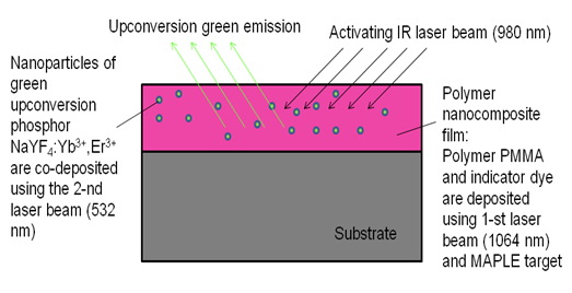 | Figure 1. Diagram explaining the principle of operation of the polymer-inorganic nano-composite upconversion film as a chemical sensor |
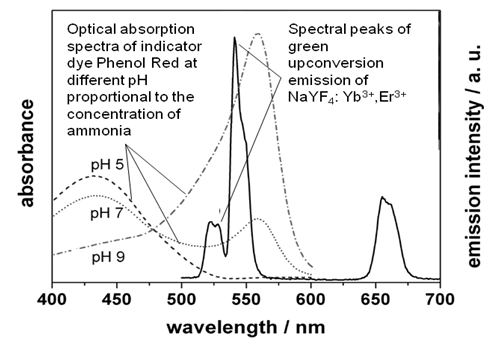 | Figure 2. Preliminary experimental results: absorption spectrum of indicator dye Phenol Red (dissolved in water) matches green upconversion spectral peaks of the phosphor |
2.1. Upconversion Phosphor
- Suitable hosts for the RE ions with efficient energy upconversion are based on materials with low phonon energies, which minimize the non-radiative multi-phonon relaxation process of the RE dopant. Very efficient upconversion phosphors are based on fluorides, such as crystalline hexagonal-phase of NaYF4 (β-NaYF4), doped with RE ions [13, 14]. In this work NaYF4 crystals co-doped with trivalent RE ions of Yb3+ and Er3+ were synthesized in powder form using the solution based technique (wet process) in the presence of Na2-ethylenediaminetetraacetic acid (EDTA) during the co-precipitation procedure to obtain homogeneous nucleation. First, 0.5 mol of NaF was dissolved in about 60 ml of water. An aqueous rare-earth chloride solution was prepared by mixing 16 ml of 0.2-mol YCl3, 3.4 mol YbCl3, and 0.6 ml of 0.2-mol ErCl3. The YCl3 solution was obtained by dissolving Y2O3 in hydrochloric acid and adjusting to pH 2 to avoid any hydrolysis. An RE (Yb or Er) chloride solution was allowed to mix with 20 ml of 0.2-mol EDTA solution for metal-EDTA complex to occur. All the RE chlorides, EDTA and NaF were obtained from Aldrich, and the Y2O3 was synthesized in the lab using Y(NO3)3 and Na2CO3 from Aldrich. The EDTA complex solution was quickly introduced into the NaF solution and the mixture was allowed to stir vigorously for several hours. After stirring, the solution was allowed to sit overnight for the precipitate to settle. The precipitate was filtered, washed several times with distilled water and with ethanol. The precipitate was dried under vacuum to remove any traces of water. The freshly prepared NaYF4:Yb3+, Er3+ crystalline powder prepared in the above procedure did not show any upconversion fluorescence. After annealing at a temperature of 400°C for one-hour, strong upconversion fluorescence from the powder illuminated with a 980-nm IR laser diode could be observed by naked eye at room illumination. As can be seen from the optical absorption spectrum of the compound in Figure 3, a laser diode with the emission peak near 980-nm is the optimal pumping source for the upconversion emission. The energy of the laser photons is mostly absorbed by the ions of Yb3+ acting as synthesizers, then transferred radiationlessly to the ions of Er3+, which generated the upconversion, higher energy photons due to the two-photon process [12].
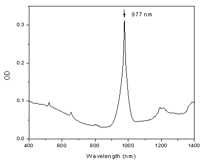 | Figure 3. Optical absorption spectrum of the NaYF4: Er3+, Yb3+ phosphor |
2.2. Polymer Host
- Indicator dye Phenol Red Sodium Salt (PR) was dissolved in Gamma-butyrolactone (GBL) at a concentration of 88 mM/L using heating to a temperature of 60°C and stirring with a magnetic stirrer. Polymer poly (methyl methacrylate) known as PMMA in powder form was added to the solution at a concentration of 1 g of solids per 10 mL of liquids and dissolved using heating (at 70°C) and magnetic stirring. In order to check the response to ammonia, a 20-µm-thick film was made on a glass slide by dipping and drying for one hour. The film had initially yellow color. After exposure to the fume (ammonia) of ammonium hydroxide, the film changed color to dark purple and returned back to yellow after the exposure. The optical absorption spectrum of the film exposed and unexposed to ammonia matched the optical absorption spectrum of PR presented in Figure 1. The “green” band of upconversion emission of NaYF4:Yb3+, Ho3+ around 540 nm fell in the ammonia initiated absorption band of the dye. It could thus be expected that in the nano-composite film containing the dye and the RE material, the green upconversion emission would be noticeably absorbed in the presence of ammonia.
2.3. Pulsed Laser Deposition
- The conventional pulsed laser deposition (PLD) of a single material onto a substrate includes the sequence of the processes: (a) heating a single target with the laser pulse; (b) melting the heated target material followed by its vaporization; (c) ionizing the atoms of the vaporized target material by the electrons accelerated in the strong electric field of the laser pulse and creating weakly ionized plasma; (d) expanding of the plume made of the weakly ionized plasma driven by electrostatic repulsion of the positive ions of the target material towards the ambient gas or vacuum separating the target from the substrate; (e) condensing of the target material from the plume on the substrate and thin film formation. Since the spread of the plume is driven by electrostatic repulsion, the axis of the plume is always normal to the surface of the target regardless of the direction of the incident laser beam. A new double-beam PLD method was used to make the nano-composite organic-inorganic reagent film [11, 12].The PLD system at Dillard University is schematically presented in Figure 4. Only laser beams 1 and 2 were used in this work. The laser beams were forced to scan over the targets with oscillating (in X and Y directions) reflectors (Figure 5) to eliminate pre-mature target erosion and cracking due to laser ablation of a target in a single spot.
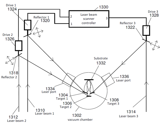 | Figure 4. Schematic of the multiple (three) beam PLD system with laser beam scanners |
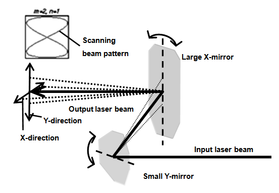 | Figure 5. Schematic of the laser beam scanner based on oscillating reflectors |
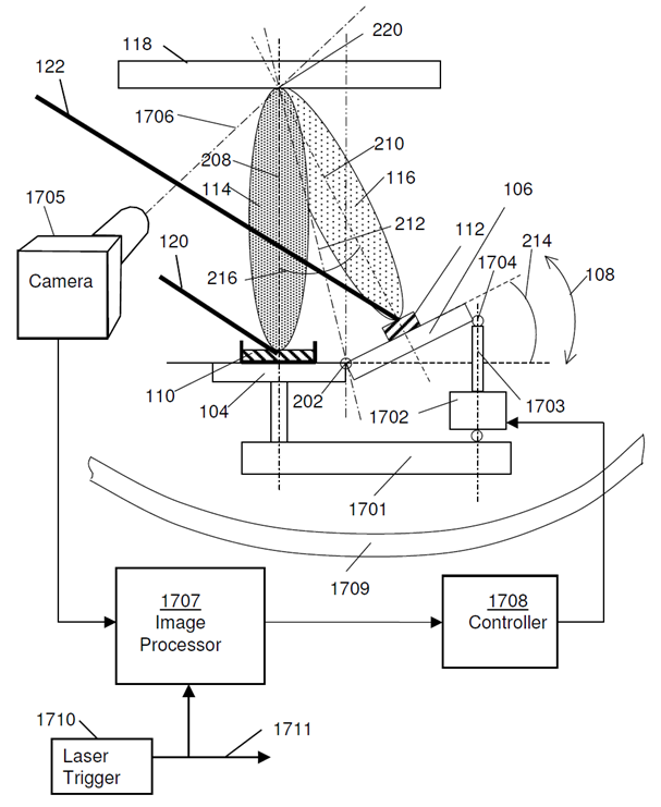 | Figure 6. Schematic of the plume overlapping control system |
2.4. Properties of the Nano-composite Films
- The morphological and optical properties of the nano-composite reagent films of PMMA-PR: NaYF4: Yb3+, Er3+ prepared by the DB-MAPLE method were similar to those described elsewhere [11, 12]. The dominant crystalline phase of the embedded nano-particles of the inorganic phosphor compound (fluoride host of the RE ions) was the hexagonal β-phase, the most favourable for the efficient visible upconversion fluorescence. The average size of the phosphor nano-particles was 5-10 nm. They were evenly distributed in the polymer matrix. The average thickness of the films was close to 20 nm. Being illuminated with a 980-nm laser diode, the films exhibited bright visible upconversion emission with the spectrum similar to that of the bulk phosphor powder (Figure 2).
3. Experimental Setup
- The prepared reagent nano-composite films were tested as ammonia sensors using the experimental setup schematically depicted in Figure 7. The photograph of the general view of the setup is presented in Figure 8.
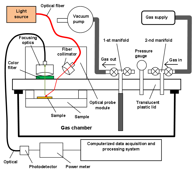 | Figure 7. Schematic of the experimental setup to investigate the nano-composite films for sensing ammonia |
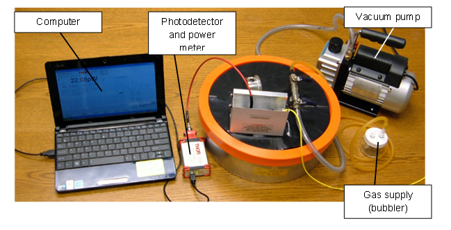 | Figure 8. Photograph of the experimental setup to investigate nano-composite films for chemical sensing |
4. Results and Discussion
- The nano-composite reagent films were exposed to ammonia using the above-mentioned setup. Figure 9 presents a typical response (the drop of the intensity of the green upconversion emission recorded with a power meter using a silicon photodetector) to ammonia (~5% molar concentration of ammonia in air). The relative humidity (RH) of the air during the exposure was ~ 50%. The film response to ammonia was not significantly affected by the variation of RH between 30 and almost 100%. Typical response time to the exposure was ~ 5 min.
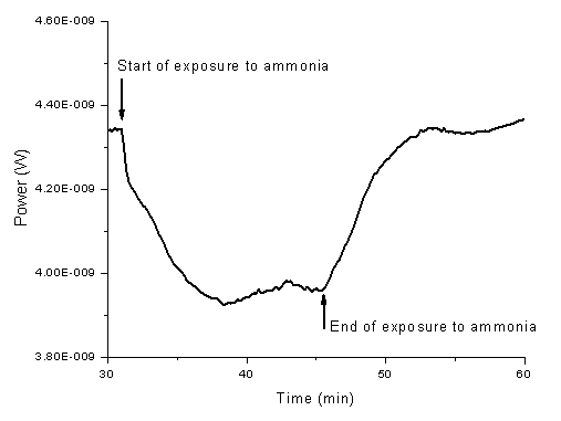 | Figure 9. Time plot of the response of the sample nano-ocomposite reagent film to the exposure to 5% ammonia in air |
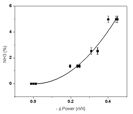 | Figure 10. Ammonia concentration plottet versus the sensor output. Solid line presents the approximation quadratic calibration curve |
5. Conclusions
- It has been thus demonstrated for the first time, to the authors’ knowledge, that the reagent nano-composite films prepared by the new DB-MAPLE method of simultaneous co-deposition of a polymer-indicator dye mixture and a RE-based upconversion phosphor could be used in chemical sensors of ammonia in air. The sensing effect is based on the increased absorption of the visible upconversion emission from the phosphor nano-particles (illuminated by an infra-red laser diode) by the indicator dye exposed to ammonia. Preliminary testing indicated that the sensor based on such films had a sensitivity of ~ 0.4% of NH3 in air and a response time of ~ 5 min. Such sensor is suitable for the applications that include detection and alarming on severe leaks from ammonia storage vessels (pressurized tanks), industrial refrigeration, and industrial ammonia transportation pipelines. Further improvement of the sensitivity might extend potential applications to the early leak detection and environment pollution hazardous to humans and animals.
ACKNOWLEDGEMENTS
- The authors like to acknowledge the support from DoD AFOSR grant FA9550-12-1-0068, FA9550-12-1-047, Army W911NF-14-1-0093, W911NF-11-1-0192, and NSF award # HRD 1002541. The authors like to thank Metal Fab south Inc. Mr. Jason and Kevin Bergeron for their invaluable machining service to the project.