-
Paper Information
- Previous Paper
- Paper Submission
-
Journal Information
- About This Journal
- Editorial Board
- Current Issue
- Archive
- Author Guidelines
- Contact Us
International Journal of Energy Engineering
p-ISSN: 2163-1891 e-ISSN: 2163-1905
2016; 6(1A): 32-43
doi:10.5923/s.ijee.201601.05

A Review on Recent Gasification Methods for Biomethane Gas Production
 Abstract
 Reference
 Full-Text PDF
 Full-text HTML
Sunil Kumar , S. K. Shukla
Department of Mechanical Engineering, Indian Institute of Technology, Banaras Hindu University, Varanasi, India
Correspondence to: S. K. Shukla , Department of Mechanical Engineering, Indian Institute of Technology, Banaras Hindu University, Varanasi, India.
| Email: |  |
Copyright © 2016 Scientific & Academic Publishing. All Rights Reserved.
This work is licensed under the Creative Commons Attribution International License (CC BY).
http://creativecommons.org/licenses/by/4.0/

Though gasification technology is upgrading and attracting researchers to invent new ways to produce good amount of useful bio-fuels, the presence of tar and hazardous gaseous contents obtained in the form of residues and also from emissions is still a major problem for many end users. Many researchers till this date have tried and tested new methods and were nearly successful in their attempts to remove tar completely. A review is conducted in search for new technologies to obtain tar free clean producer gas. In this paper focus is lead on methods applied for pre-treatment of biomass for cracking down the complex polymer structure - lignocellulose into porous materials, advantages of using agriculture sludge as biomass fuel, ways to obtain a sludge feedstock composition which would not lead to tar formation during gasification process, modification of gasifier design and operating parameters, In-situ catalytic conversion methods to crack down large hydrocarbon molecules if ever they are formed, cleaning techniques to remove tar and other impurities, up-gradation of product gas to methane for higher calorific value. Based on the information collected, a pilot design of the gasification plant will be proposed for achieving a clean tar free product gas or biogas.
Keywords: Gasification, Syngas, Biomass, Tar, Filtration, Design Parameters, Diesel blending, Bio-methane
Cite this paper: Sunil Kumar , S. K. Shukla , A Review on Recent Gasification Methods for Biomethane Gas Production, International Journal of Energy Engineering, Vol. 6 No. 1A, 2016, pp. 32-43. doi: 10.5923/s.ijee.201601.05.
Article Outline
1. Introduction
- In the present scenario demand of electricity increases day by day but the power sector cannot fulfill this demand completely. Agriculture industries influences large part of the economy in India and having a huge amount of biomass like wood, bio-waste. At present to fulfill the shortage of power supply diesel generators are extensively used to produce electricity in rural and hilly areas. These generators produce grate amount of emission which affect the surrounding environment. In this quest it is our need to usage clean and eco-friendly bio-fuel which will not harm the environment and help to produce electricity independently without need of external power supply sources.Human evolution in a period of fast growing era, man’s dependency increases on various energy forms like thermal, electricity, mechanical and hydro. But at the same time the available conventional energy resources are being exhausted at a faster rate so it is need to focus on the technology to produce energy from the renewable sources. And hence we can save the nature. Solar, hydro, Wind energy’s are available in abundance but the immediate conversion of these energy’s into useful form is not so easy and therefore biomass comes into the picture. Biomass is formed from living species like plants and animals. It is a collection of organic and inorganic materials mostly consists of by-products and wastes form animals and agriculture. Biomass is considered renewable because of unlike fossil fuel and can be reproduce plant through crop harvesting and consumption of food by the animals. Plants absorb carbon dioxide for their growth and return back to the atmosphere it means it will not disturb carbon dioxide level in atmosphere and therefore biomass is considered as “Carbon Neutral Fuel” [1]. According to the estimated data provided by the Ministry of new and renewable energy of India, there is about 500 million metric tons of biomass available every year and 120 – 150 million metric tons of agriculture and forestry residues are available in surplus amount per annum which have the potentiality to generated 18000 MW of power and additional 5000 MW power can be generated using bagasse as biomass fuel in 550 sugar mills running currently in India. Currently, bagasse is been used extensively as biomass fuel in as many as 288 biomass co-generation projects summing up to 2665 MW power generation capacity, which were installed in sugar mills running in 16 leading states of India [25].Extraction of biofuels can be done in two methods, anaerobic method and thermal conversion method. Anaerobic method uses fermentation procedure to extract ethanol and methanol fuels, review in this area is not within the scope of this paper. Thermal conversion method involves pyrolysis, partial combustion and reduction or gasification reactions. The whole process is termed as Gasification, which converts the available biomass into bio-fuels like product gas, syngas, biogas etc. The main constituents present in the product gas are carbon monoxide, Hydrogen, carbon dioxide, methane, water vapor, nitrogen oxides, tar (Heavy Hydrocarbons), sulphur compounds and particulate matter. The major component which cause problem is still in the biomass industry is Tar.Since two decades lot of research efforts were invested on modifying the design of the reactor, changing the operating and design parameters, modifying filtering techniques, using various catalytic converters to efficiently break down the Tar components or convert them to carbon monoxide or carbon dioxide and water vapour etc. Detailed discussion types of biomass pre-treatment processes for cracking down the complex polymer structure - lignocellulose into porous materials, advantages of using agriculture sludge as biomass fuel, ways to obtain a sludge feedstock composition which would not lead to tar formation during gasification process, modification of gasifier design and operating parameters, In-situ catalytic conversion methods to crack down large hydrocarbon molecules if ever they are formed and for yielding higher percentage of CO and H2 cleaning techniques to remove particulate matter and other impurities, up-gradation of product gas to methane to increase the calorific value.
2. Pre-Treatment of Biomass
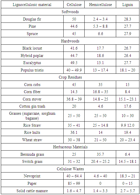
- The common entity present in the agricultural based biomasses is the chemical structure containing cellulose, hemicelluloses and lignin. Materials having these structures are called as Lignocellulosic materials. Wood, wood wastes, sugar cane bagasse, sweet sorghum, rice straw, nut shells, corn stover, corn cobs, grasses, wheat straw, banana waste, solid cattle manure, cotton seed hairs, newspapers, etc, are few lignocellulosic biomass materials which can be used as feedstock for anaerobic or thermal conversion gasification processes.Survey shows that lignocellulose is the main source for generation of renewable energy [26] from biomass and it is also the main source for the formation of primary, secondary and tertiary tar products during gasification. Detailed experimental analysis was performed to check on the severity of the pyrolytic reactions with temperature and time as functions [25]. Cellulose derived products like the levoglucosan, hydroxyl acetaldyhyde and furfurals, hemicelluloses derived products and lignin derived methoxyphenols are termed as the primary tar products. On further cracking phenolics and olefins are formed which are classified as secondary tar products and when subjected to high temperatures about 900°C the secondary tar products change to alkyl tertiary products like toluene, indene, methyl naphthalene and other methyl derivatives, these tertiary products when condensed at high pressures and temperatures benzene, naphthalene, acenaphthylene, pyrene, anthracene etc. are formed but low yields [25]. Therefore pre-treatment process is an essential method to deconstruct these complex lignocellulosic structures into simplest molecular particles having the required energy and would not cause any tar formation during the gasification. Table 1 shows the list of lignocellulosic biomass materials with their respective cellulose, hemicellulose and lignin contents. The table shows that cellulose constitutes larger proportion in most of the biomasses. It accounts for more than 50% by weight and has a linear homopolymer of glucopyranose residues linked by β-1, 4 – glycosidic bond [29].
|
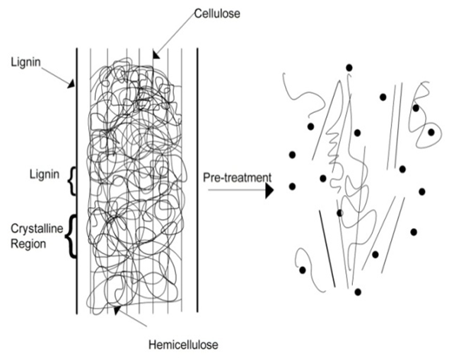 | Figure 1. Schematic representation of Pre-treatment process on lignocellulosic material [30] |
3. Downdraft Gasification
- Gasification technology is basically process for converting solid or liquid feed stock into a gaseous or liquefied fuel that can be burned to release energy [1].There are many gasifier reactor have been designed depending on their uses. Gasifier are mainly three type- Fixed-bed type, Fluidized-bed type and Entrained-flow type these types are classified according the type of feed stock used. In this paper we are using downdraft gasifier for gasification. The feed stock is feed from the top of the gasifier through hopper and the gasifying agent like air , oxygen or steam is introduced from the sides of the reactor at combustion zone. The gasification process involve complex combination of pyrolysis and oxidation where the biomass start converting gaseous form and release CO, H2O, CH4, CO2, H2, NOx and tar.
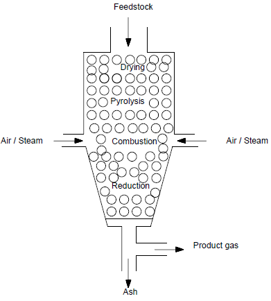 | Figure 2. Downdraft gasifier |
4. Chemical Reactions
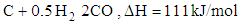
- Chemical reactions in the gasification process are listed down [1].
 | (1) |
 | (2) |
 | (3) |
 | (4) |
 | (5) |
 | (6) |
 | (7) |
 | (8) |
 | (9) |
 | (10) |
 | (11) |
 | (12) |
 | (13) |
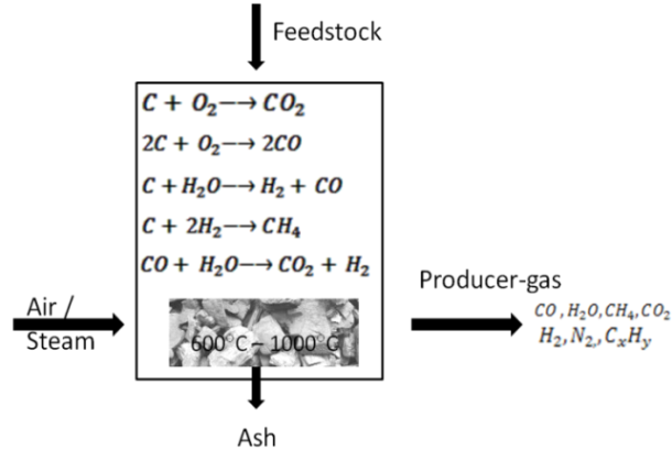 | Figure 3. Typical Outline Sketch of Gasification Process |
5. Design and Operating Parameters
- Biomethane extraction from the producer gas depends on the quality of the gas produced by gasifier. Methane product can be easily extracted if the yield of methane is high in the product gas. Gasification process design play a major roll on quality, yield and composition of the product gas to obtain a purified SNG. Following parameters are reviewed in order to construct process plant based on literature survey.
5.1. Biomass
5.1.1. Biomass Type
- Agriculture waste sludge materials like Rice husk, wheat straw, wood chips, saw dust, cow manure, bagasse are chosen because of its availability and various advantages [2].
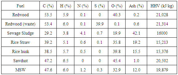
5.1.2. Ash Content
- Proximate analysis gives the detail of amount of ash present in the biomass. If less ash content presents in the biomass it means the quality of gas is good and it also improve the gasifier performance. From the observation Table 2 only wood biomass having lower ash content compare to other biomass. This clearly says that the wood type biomass is more favourable [1].
|
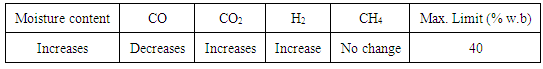
5.1.3. Moisture Content
- Moisture presence in the biomass affects the calorific value of product gas, heat input, gasifier performance and concentration of CO, H2 and CO2.From the data available in Table 3 as the moisture contents increase in the biomass the concentration of CO2 and H2 increases whereas the CO decreases, there is no effect on production of CH4. When wood is used as a feed stock in downdraft gasifier, the maximum permissible limit of moisture content is 40% [1, 2, 3].
|
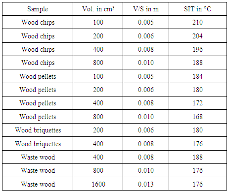
5.1.4. Ignition Temperature
- Behaviour of the combustion reaction rate solely depends on the self igniting temperature of the biomass. Maintaining this temperature or above it would make the biomass self-sustained, providing required heat energy to carry out endothermic reactions such as Drying, Pyrolysis and Reduction reactions. Most of the biomass materials are volatile in nature, therefore the required temperature to burn is not high compared to the coal and other fossil fuels. From the data provided in [1, 7] show that most of the wood biomass materials are having the self ignition temperature ranging between 160°C and 220°C. The Table 4 conveys that the ignition temperature decreases with increase in volume of the wood feedstock fed into the gasifier, in the form of chips, pellets or briquettes [6]. V/S means ratio of volume over surface area of the sample.
|
5.1.5. Feedstock Pellet Size
- Dimensioning of the wood biomass into a uniform shape will increase the performance of the gasifier. On comparing different sizes of the pellets, it is found that smaller the pellet size better the gasifier efficiency and quality of the gas. From the information provided, out of the 12mm, 8mm and 6mm sized pellets, gasification using 6 mm sized roundwood feedstock gave 56.7% Cold gas efficiency. Wood logs and bark chips which are even more smaller than the pellets have shown better performance. [7].
5.1.6. Feedstock Pre-Processing
- Pre-processing involves preparing the biomass fuel to a permissible level which helps in yielding a quality gas. Pre-processing influences the heating rate, energy consumed to remove moisture and tar, ash fusion temperatures. Each biomass type contains different compositions with varying organic and inorganic elements in it. Alkali and alkaline earth metals and other metals like silica, sulfur and chlorine are the main inorganic elements which participate in undesirable reactions in the combustion chambers leading to critical problems of fouling and slag during gasification process. [6, 7]
5.2. Product Gas
5.2.1. Desired Composition
- Clean product gas has following components like CO, H2O, CH4, CO2, H2. Syngas composition depends on the chemical composition of the feed stock feed into the gasifier. Typical syngas composition are CO (35% - 40%), H2 (20% - 40%), CO2 (25% - 35%), CH4 (0% - 15%) and N2 (2% - 5%). The main object is to produce large amount of bio-methane (Natural gas). Syngas (SNG) can be obtained after filtration and purification of product gas.Syngas has high conversion efficiency so through methanation process it can be converted to bio-methane. High amount of CH4, H2, CO and proportionally negligible amount of N2 is desirable.
5.2.2. Power Output
- Required power output for generation of electricity is an essential input parameter. Based on this parameter, amount of fuel to be fed into the gasifier and amount of gasifying medium to be used for combustion reaction can be estimated [1].
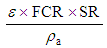
5.2.3. Flow Rate of Product Gas
- Following expression gives the volume flow rate of the producer gas (m3/s) [1].
 | (14) |
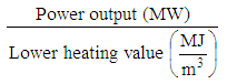
5.2.4. Higher Heating Value
- High heating value of a fuel is defined that the amount of heat released by a specific quantity of fuel is combusted. Paper [9] provides a detail data of lower and higher heating values of various fuels. The higher heating values for gaseous, liquid and solid fuels, Natural gas has 52.225 MJ/kg, Diesel has 45.766 MJ/kg, Gasoline has 46.536 MJ/kg and Hydrogen has 142.18 MJ/kg. These data clearly stated that the Natural gas has the potential to the other conventional fossil fuels after hydrogen [9].
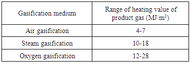
5.2.5. Gasifying Agents
- Air, steam and oxygen are three gasifying agent. The selection of gasifying agent depends on the heating value and composition of the product gas. Table 5 shows the HHV of product gas using different gasifying agents. In atmosphere, air has 79% of N2 and 21% of O2, the oxygen is the active part in combustion but at high temperature N2 gets oxidized and form NOx which lowered the calorific value of product gas then the product gas produced by other gasifying agent like steam or pure oxygen.
|
5.3. Design Parameters of Gasifier
5.3.1. Gasifier Type
- Downdraft gasifier is preferred because it removes more amount of tar, better efficiency (70 – 85%), low cost and suitable for wood gasification.
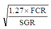
5.3.2. Reactor Height
- The reactor height from top to bottom can be finding by the use of this expression. The parameter depends on SGR, operating time and density of the fuel [4].
 | (15) |
5.3.3. Reactor Diameter
- Following expression is used to determine the reactor diameter [14].
 | (16) |
5.3.4. Throat Design
- Gasifier throat is nothing but the reduction of area just before the oxidation zone which provide the uniform motion to devolatilized or pyrolized biomass and allowing uniform distribution of temperature and sufficient time for tar cracking into small molecules of hydrocarbon. Throat dimensioning is related to the “Hearth Load” concept.
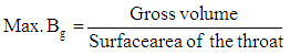
5.3.5. Hearth Load (Bg)
- Hearth load is the ration of amount of fuel consumed to the surface area of the throat (Bs), expressed as Kg-m3/cm2-h. It is given that for one kilogram of dry fuel under normal conditions produces about 2.5 m3 of producer gas. The relation between Bg and Bs is given by: Bg = 2.5 BS. Hearth load depends on the temperature and heat insulation of hot zone. A maximum value of 0.9 indicates that the gasifier is in good operation. Higher value of hearth load increases the pressure drop over the reduction zone of the gasifier. The gasifier produces lass tar or tar free when it should be properly insulated and maintained the hearth load value between 0.15 and 0.18 [3].
 | (17) |
5.3.6. Insulation
- In gasification process temperature plays a major role. Quality and composition of the product gas are very much affected by the temperature fluctuation. From temperature range 200°C to 800°C active oxidation reaction occurs and from 800°C to 1200°C tar is cracked into smaller gaseous molecules. Average of about 1000°C temperature is maintained continuously. Due to improper reaction heat loss occurs thereby consumption of biomass fuel increases and gasifying medium lead to decrease gasifier efficiency.It is essential to conserve the heat generated by the combustion reactions in the reactor. Corrosion of inner layer of the gasifier is another problem to be taken care of. Good insulation, non-corrosive and long life material at high temperatures must be selected. Materials which can withstand high temperatures are stainless steel, firebricks, ceramics, refractory materials like cement, copper, brass, alumino-silicate. Among these stainless steel is bit expensive as it requires inert gas welding techniques, with copper and brass are also expensive and are costlier compare to other materials from the list. Instead, alumino-silicate material, a high-temperature insulation wool (HTIW) is recommendable as it is light weight, capable of withstanding temperatures upto 1500°C, high durability, better heat-flow resistance and inexpensive [10].
5.3.7. Cyclone Separator
- It is one of the dry collectors which remove dust, droplet, and ash particles at low cost and low maintenance. The operating principle of the cyclone separator is that it paves a rotary path to the gases, increasing the settling rate by many times than the gravitational separators. The detailed design principles and selection strategies are available [10, 38].
5.4. Operating Parameters of Gasifier System
5.4.1. Residence Time and Heating Rate
- Residence time and heating rate go hand in hand in every zone. These parameters affect the tar levels, phase transformations of the biomass fuel. Different products are obtained for different values of these parameters. A pre-heated feedstock, heating rate gets faster and residence time is brought down to lesser time period for yielding the same product. Carlos [8] explains the effects of pre-heating feedstock with various pellet sizes on heating rate and resulting constituents of the product gas.
5.4.2. Air Flow Rate
- Air is a gasifying agent used in combustion zone to partially oxidize the devolatilized biomass. The parameter is useful to determine the fan size or blower which is need to fixed along the sides of the reactor. Parameter depends on equivalence ratio, fuel consumption rate, stoichiometric rate of fuel and density of air. Air flow rate can be calculated by given expression.
 | (18) |
5.4.3. Operating Temperature
- Amount of oxygen feed to the gasifier system depends on the operating temperature. Oxidation reactions are exothermic reactions which release heat energy that become the source of whole gasifier system to work properly and to process pyrolysis and combustion zone also. Once the gasifier temperature reaches the self ignition temperature of the biomass then the gasification process becomes self sustaining and solely depends on the oxygen source [10].
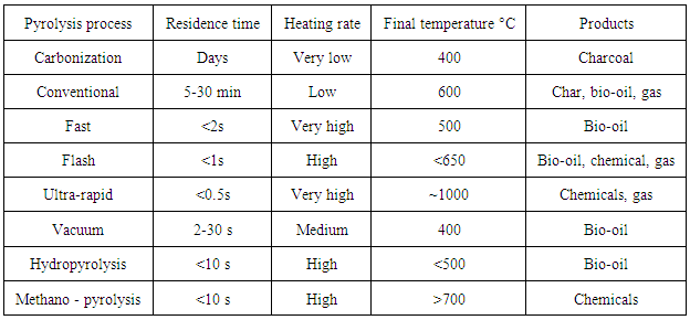
5.4.4. Equivalence Ratio
- Equivalence ratio (ER) is the ratio of actual air-fuel ratio to stoichiometric air - fuel ratio. The parameter refers when air and oxygen is used as a gasifying agent. It helps to determine the tar concentration present during gasification. By increasing the ER tar formation in the product gas can be reduced. High ER means greater oxygen content allowed to react with the volatiles present in the combustion zone. When air is used as gasifying agent for gasification process the suitable value for ER is between 0.25 to 0.3. Variation in the ER affects the energy in the product gas, gas composition, gasification temperature and conversion of energy from char to gas. For complete oxidation of biomass with air a weight ratio (mass of air / mass of biomass) of 6.36 is required whereas with oxygen a weight ratio of 1.476 is needed. So to convert all char into gas as Equivalence ratio 0.25 has been more preferred.The conversion rate of part of wood energy to gas reaches maximum. Air filtered from nitrogen, dust particles and other impurities enters the reactor with more oxygen content. Using such a filtered air is recommendable to improve the efficiency of the gasification and quality of the product-gas.Table 6 provides information on the products obtained by heating the biomass at different heating rates and residence times. Depending on the combination of set of parameters, pyrolysis is classified into various processes. When biomass is set to undergo the devolatilization process, with very low heating rate and very slow residence time carbonization reactions are observed which yield charcoal as the product, if heating rate is maintained low and decreasing the residence time to 5 – 30 minutes then a conventional pyrolysis process takes place at temperature of 600°C producing char, bio-oil, and gas as products. Likewise, by increasing the heating rate and allowing less residence time, bio-oil, chemicals and gas are the main products obtained at different proportions respectively.
|
6. Tar Formation
- After thermal or partial oxidation of biomass material it produce tar which is undesirable aromatic by product having condensable hydrocarbon, complex polyaromatic hydrocarbon and oxidized 1-5 aromatic ring.
6.1. Classification of Tar
- Tar is classified into four major types [11].1. Primary products: Hydroxylacetaldehyde, Levoglucosan, furfurals, analogous hemicellulose-derived products and lignin-derived methoxyphenols.2. Secondary products: Olefins and phenolics.3. Alkyl tertiary products: Include methyl derivatives of aromatics, acenaphthylene, methylnaphthalene, toluene and indene.4. Condensed tertiary products: PAH series like benzene, naphthalene, acenaphthylene, anthracene/ phenanthrene, and pyrene.Temperature and gas phase residence time is the function of transformed tar product. Tar formation at different temperature is shown by given equation. The process as follows when biomass reaches its self ignition temperature about 250°C, due to partial oxidation reactions under low pressure and 400°C temperature a part of biomass fuel start to transformed into primary vapours (oxygenates) then these oxygenate convert into light hydrocarbons aromatic like phenolic ethers at 500°C, then at 600°C it convert into alkyl phenolics, then heterocyclic ethers at 700°C, then at 900°C and above the large complex polyaromatic hydrocarbons are formed. Finally these large molecules get cracked down to CO, H2, CO2, H2O and upon condensation form soot and coke.
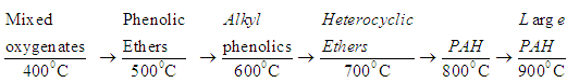 | (19) |
7. Product Gas Cleaning Methods
7.1. Tar Reduction Techniques
- Tar can be eliminate by two methods: Primary method, in which tar reduces inside the gasifier system and second method in which tar eliminates outside the gasifier system by several approaches like physical separation or thermal cracking, plasma assisted cracking or catalytic reforming. Few strategies are suggested by Y. Neubauer [13] to reduce tar production. The combination of primary and downstream utilization technique would be effective in tar removal. Steps involved are:
7.1.1. Staged Gasification Systems
- Multistage downdraft gasifier is good option to improve the gasification efficiency and reduce the tar contents present in the product gas. In this approach the four reaction zones are separated to each other, the process start from drying followed by pyrolysis, combustion and reduction. List of few staged gasifier names are: Viking gasifier, TK Energi AS, Clean ST Gas, Xylowatt. The tar concentration in product gas is comparatively very low in these gasifiers. Ulrik Henriksen et al. [14, 15] shows the performance details of Viking gasifier that is gasifier efficiency is about 93%, tar and dust level are less than 5.
7.1.2. Use Catalytic Active Bed Materials as Additives in the Biomass
- Following are the catalytic active bed material used as additive in the biomass these additive or catalyst are dolomite, limestone, olivine sand, bauxite, lanthanum, alumina, nickel aluminate, cobalt, natural clay minerals and iron minerals [17]. Active carbon, calcined dolomite, Y-zeolite at 550°C are the best suited for tar removal after investigating the many catalyst by different visitors [17]. These additives needs throughout mixing with the biomass before starting pyrolysis process. Yafei Shen et al. [16] deals with In-situ catalysis using Silica – Based nickel nano particles embedded in rice husk char. Nickel catalysts embedded rice husk are prepared and tested in various proportion during gasification process as a result small amount of PAHs and simple molecular structure of tar compounds are found. The formation of tar can be reduce or eliminate by the use of Ni catalysts but this approach is bit expensive as the additives have to be replaced after few hours of operation with new bed. Instead of Bio char the In-situ catalyst is more useful, cheaper and efficient to remove heavy PAHs like toluene, benzene. Activated carbon has higher surface area and thereby it has higher removal efficiency of 69% to 92%. Removal of toluene can be increased by 10% at higher temperature 800°C [18].In the case of In situ catalyst, Bio-char derived catalyst was found potential enough to remove most of the tar content. Biochar is the byproduct of the biomass gasification. Researchers in Okhlahoma state university have processed the bio-char catalyst consisting of original biochar, biochar – derived activated carbon and biochar – derived activated carbon with acidic surface. Results showed that tar was removed by 92% and with increase in reactor temperature the toluene removal efficiency was increased by 3 to 10%. [37].
7.2. Downstream Utilization Technique
7.2.1. Cyclone Separator
- Cyclone separator is attached at the outlet of the gasifier system to remove dust particles and other solid impurities grather then 10μm size [10]. The design of cyclone separator can be scaled up according to the desired dimension of gasifier size.
7.2.2. Bag House Filter
- To capture dust particles the bag house filters are widely used. The gas passes through this fibrous bag which is enclosed inside the metal caged chamber. The dust particles are accumulated inside the bag. Once the dust cake is completely block the bag then it need to remove by manually or to apply pressurized gas to its proper functioning.
7.2.3. Reforming Char Catalyst
- The bio-char catalyst, used in the reduction bed can be used outside the gasifier as a downstream catalytic converter. Catalysts supported by char have been proven to show high potentiality for reforming of biomass tar. Nickel additive is efficient enough in reducing tar. Although Nickel based char can be used in tar reforming but a comparison study shows that char supported Iron catalyst is better for tar reforming application than Ni supported char catalyst [19].
7.2.4. Scrubbing System / Gas Washing
- For filtering producer gas, wet scrubbing system also used. This scrubbing system works on the principle of Brownian motion of the particles with diameter between 0.1 to 1 μm. This filtering system is able to remove 49% of heavy tar, 62% of light tars and 79% of hydrocyclic contents with a dew point at around 180°C but the main problem with is system is that during process water and tar gets mixed with each other and form sticky polymeric liquids which cannot be decomposed anywhere [20].In recent years a new system has been developed by ECN known as OLGA system in Netherlands. In this system dust, tar and water are not allowed to mix. OLGA runs on basis of dew point control. The technology developer mainly ECN and Dahlman Industrial group assure that OLGA eliminates 100% - heavy tars, 100% - light tars, 99% Heterocyclic contents with dew point maintained below 20°C.
7.2.5. Catalytic NOx Absorber
- If air is used as the gasifying agent then the oxides of nitrogen are formed due to high temperature oxidation reactions. Catalytic converters like SCR, EGR and Adsorption techniques were used to remove NOx molecules from exhaust gases. Few papers have reviewed on methods to filter NOx. Energy research centre investigates results on absorption of Nitrogen oxides in alkaline solution of sodium hypochlorite in a packed column. Results of the above investigations shown that the absorption work efficiently which depends on parameters like gas velocity, spraying density, concentration of nitrogen oxides in gas and concentration of spraying solution [20].
7.2.6. Sequestration of CO2
- For storage and capturing of CO2 is still under research phase. Number of methods has been tested to sequester CO2. Caron dioxide scrubber is one such device uses catalyst like amines, minerals-zeolites, lithium hydroxide, sodium hydroxide and activated carbon to absorb CO2. Among these catalysts activated carbon is cheap source and available in large quantity and thereby it is used as a catalyst to absorb CO2. Once catalyst gets saturated it can be regenerated by blowing ambient air and collect accumulated CO2 and then reuse it in scrubber [22].
8. Methanation
- Methanation is the last stage process in the purification of the product gas. The product gas has to be tar free and has less concentration of CO2. The remaining CO and CO2 left in the gas will undergo catalytic reaction with hydrogen to form methane.
 | (20) |
 | (21) |
9. Literature Review Gap and Future Research Direction
- The development of the gasification technology involves many stages involving process planning, component selection and designing, fabrication, assembly, experimentation and validation. From the reviews, it is found that most of the researchers have started from the second stage, followed with third and fourth stage. Figure 4 shows the flow diagram of the planning stages, first stage focuses on the process planning. Based on the objectives put forward in this paper, large part of efforts has to be invested on the formulation of the biomass fuel to reduce Tar formation to negligible levels. There are two important issues which have to be dealt, Firstly, efforts on analysis of various feedstocks developed through combinations of agro based waste products with cattle manure is required as there is little information provided from the literature survey. Secondly, design of selective catalytic reduction type catalytic converter for gasification process.
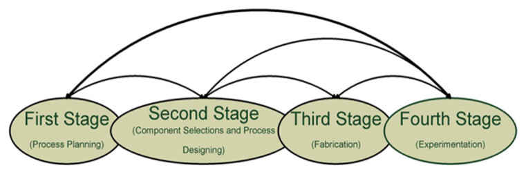 | Figure 4. Planning stages for development of gasification technology |
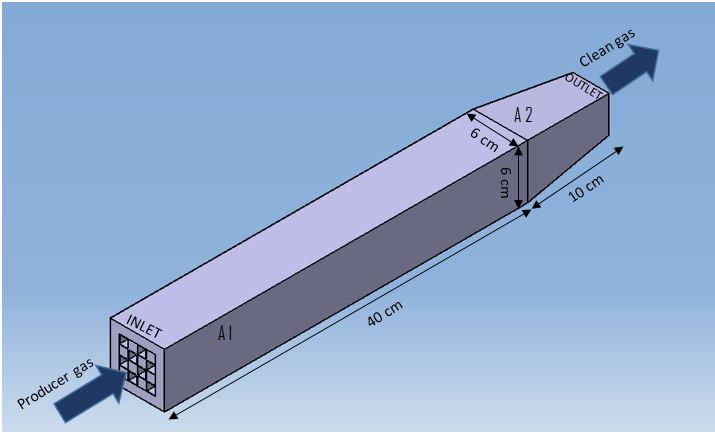
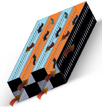 | Figure 5. Cross-section view of a selective catalytic reduction type novel catalytic converter |
 | Figure 6. Catalytic converter with outer casing |
 | (22) |
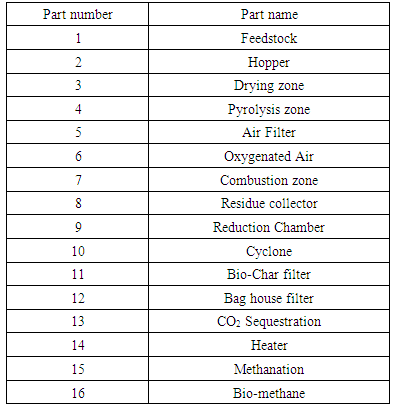
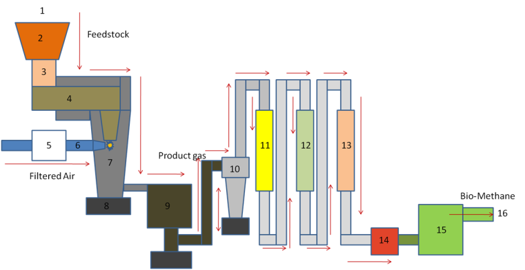 | Figure 7. Proposed pilot plan of multistage downdraft gasifier |
|
10. Conclusions
- Review of the literature survey highlights that many innovative approaches have been implemented by the researchers to improvise gasification process. With the help of technology advancements, gaps which were once left behind like Tar removal are gradually being filled by close observations and analyzing the complexity in the processes. Deep study of the variations in the biomass characteristics has provided few clues on how to batter the Tar and NOx pollutants and other impurities. Pre-treatment of the biomass and preparation of the feedstock would resolve the issue of Tar to large extent. By using effective catalyst like nickel based catalyst would reduce NOx in the producer gas. Designing a novel catalytic converter for removing impurities in the gas would provide clean producer gas. Pilot work is essential for broadening the know-how in the gasification process, thereby paving way for structuring efficient gasification process.
ACKNOWLEDGEMENTS
- The authors gratefully acknowledge the MHRD New Delhi for financial support under Centre for Energy and Resources Development (CERD) to perform this study.