S. D. Pandey 1, V. K. Nema 2, S. K. Shukla 3
1Faculty of Engineering, KNIPSS, Sultanpur, India
2G.R.D.K. Institute of Science and Technology, Jabalpur, India
3Dept. of Mechanical Engineering, IIT (BHU), Varanasi, India
Correspondence to: S. D. Pandey , Faculty of Engineering, KNIPSS, Sultanpur, India.
| Email: |  |
Copyright © 2016 Scientific & Academic Publishing. All Rights Reserved.
This work is licensed under the Creative Commons Attribution International License (CC BY).
http://creativecommons.org/licenses/by/4.0/

Abstract
A jaw crusher breaks minerals, ores of high strength. The stiffness of swing jaw plate has not been varied with changes in rock strength. Thus stiffness of swing plate is enough to crush taconite with an unconfined compressive strength (QU) of up to 308 MPa, may be over signed for softer fragmental. Hence the weight of the swing plate is necessary to reduced. In this paper, work can be done with help of Point-Load Deformation Failure (PDF) relationship along with interactive failure of rock particles. Design of a plate is carried by using CATIA software. The finite element analysis (FEA) will be carried out by using ANSYS software. The changes found in corrugated swing jaw plates behaviour are calculated with the traditional jaw. The modified stiffened plate model is estimated to reduce the consumption of energy by 35%.
Keywords:
Jaw Crusher, Point-Load Deformation Failure (PDF), Corrugated Jaw plate, Stiffened-Jaw Plate
Cite this paper: S. D. Pandey , V. K. Nema , S. K. Shukla , Theoretical Analysis of Swing Jaw Plates used in Heat Exchanger, International Journal of Energy Engineering, Vol. 6 No. 1A, 2016, pp. 23-31. doi: 10.5923/s.ijee.201601.04.
1. Introduction
Crushing is the process of reducing the size of the lump of ore or over size rock into definite smaller sizes. Based on the mechanism used crushers are of three types namely Cone crusher, Jaw crusher and Impact crusher. The first stage of size reduction of hard and large lumps of run-of-mine (ROM) ore is to crush and reduce their size. The mechanism of crushing is either by applying impact force, pressure or a combination of both. The jaw crusher is primarily a compression crusher while the others operate primarily by the application of impact. The crusher crushes the feed by applying pressure, impact and shearing effect or combined action by contacting the moving units against a stationary unit or against another moving unit. The crushers are very much rugged, massive and heavy in design and contact surfaces have replaceable high tensile manganese or other alloy steel sheet having either flat or corrugated surfaces. Many engineering structures consist of stiffened thin plate elements to improve the strength/weight ratio. The stiffened plates subjected to impact or shock loads are of considerable importance to mechanical and structural engineers. The main aim of the present work is to propose an efficient use of modeling in the connection between the plate and the stiffener, and as part of it the constraint torsion effect in the stiffener.The objective of this paper is to increase the design and analysis of commercially available swing jaw plates (including stiffening elements), having 304mm opening at top and 51mm at bottom and 0.9 m wide. The theoretical design calculations of jaw plates have been computerized. The design and modelling of crusher’s jaw plates is accomplished by using CATIA, by using this package three dimensional model of jaw plate has been developed. Finite Element Analysis of jaw plates are carried out by using ANSYS 12. This work is extended to improve the strength / weight ratio of swing jaw plate by adding different number of stiffener elements on the jaw plates.
2. Design of Jaw Plates
Today’s industry is concerned about energy consumption in crushing. At present engineers are focussing on ways to decrease the weight (and consequently the stiffness) of the swing plate of jaw crushers to match the strength of the rock being crushed. An investigation of the energy saving of plate rock interaction when point load deformability and failure relationships of the rock are employed to calculate plate stresses. In order to conduct this investigation, a model has been created in the modeling software CATIA and then with the help of finite element analysis software ANSYS analysis it. Firstly, the model will be analysed without stiffeners and then further analysis is continued by adding the stiffeners to the model. Influence of the stiffeners on the strength of the jaw plate will be discussed by using the results obtained from FEA simulation.The factors of importance in designing the size of jaw crusher’s plate are: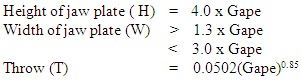 where the crusher gape is in meters.These dimensions vary between various manufacturers catalogue as they have their own specifications and design. The dimensions chosen for this paper is, Top opening i.e. gape 304 mm (12 in.) and bottom opening 51mm (2 in).
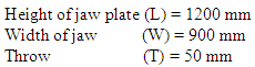
3. Modeling of Swing Jaw Plates without Stiffeners
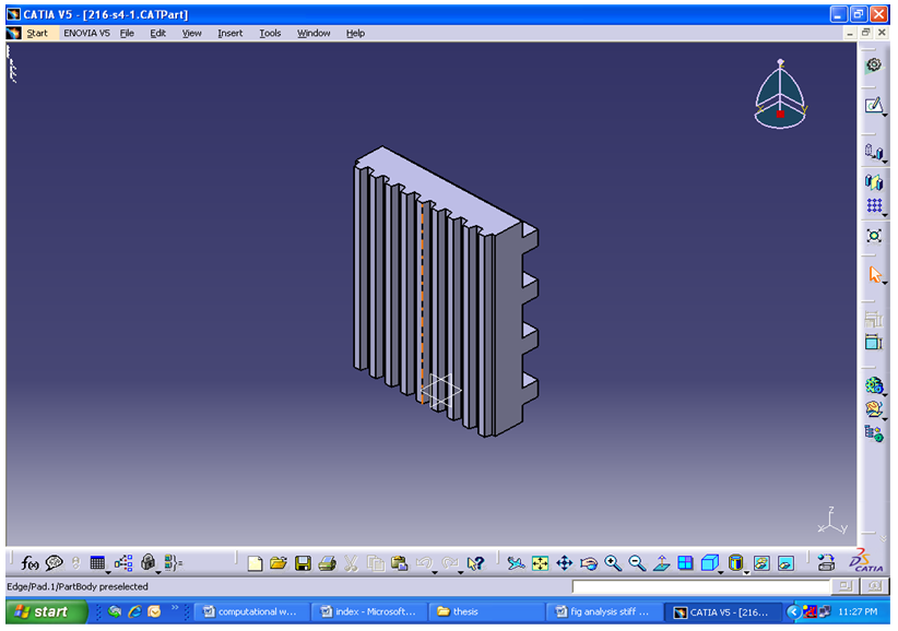
All The modeling of swing jaw plate is done with CATIA, here different thickness are taken and then this plates are analysed.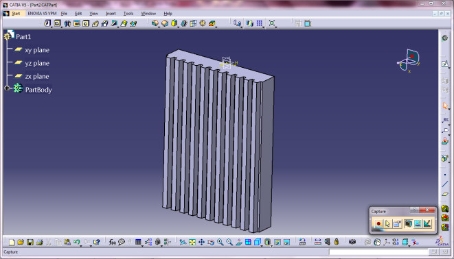 | Figure 1. Solid Model of Corrugated Swing Jaw Plate |
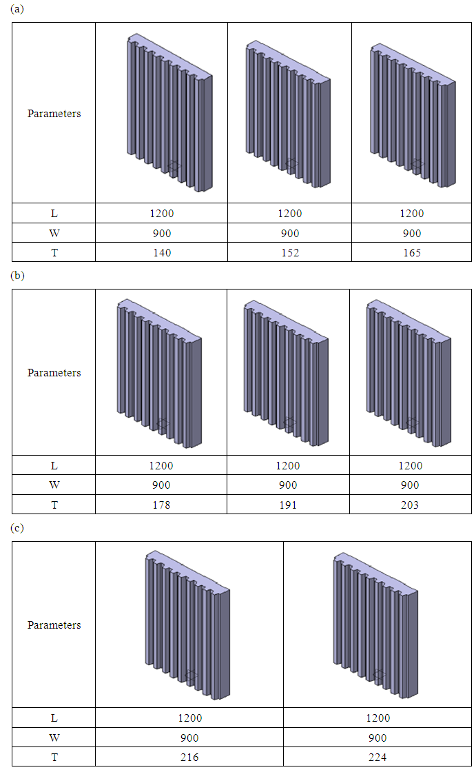 | Figure 2. (a), (b), (c), Corrugated Swing Jaw Plate Models having Dimensions in mm |
Assumptions:Analysis was undertaken based on the assumption that the point load strength of the disk and irregularly shaped particles to be equal and tensile point loads of different particle sizes are acting normal to the plate. For the analysis of the of swing jaw plate, the model of the swing jaw plate is converted into IGES file and then this file is called for the analysis.
3.1. Applying Materials
Before the Structural Analysis module is used for the FEA model, it must have material assigned to it. Each material in ANSYS has mechanical properties for computing the analysis for different materials but it has a facility to edit and add some material properties for other parts. For the analysis of plate. Martensitic steel are use, because it is hardenable, which means that it is possible to modify the properties via heat treatment in the same way as for hardenable carbon steels.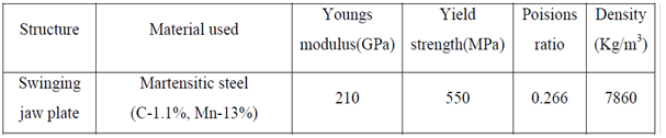
3.2. Apply Boundary Conditions
Boundary condition for Swing jaw plate is simply supported i.e. the support at bearing location hinge support and at the free end toggle force acting. due to which this plate is acts as a simply supported, figure shows the fixed point of plate. 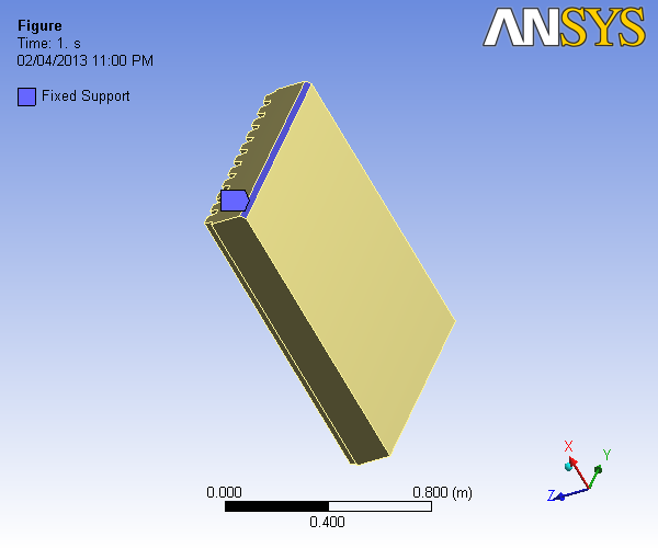 | Figure 3. Showing Swing Jaw Plate Model Boundary Condition |
3.3. Applying Loads
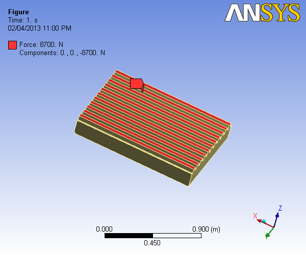 | Figure 4. Showing loading condition on Swing Jaw Plate |
3.4. Linear Static Stress Analysis
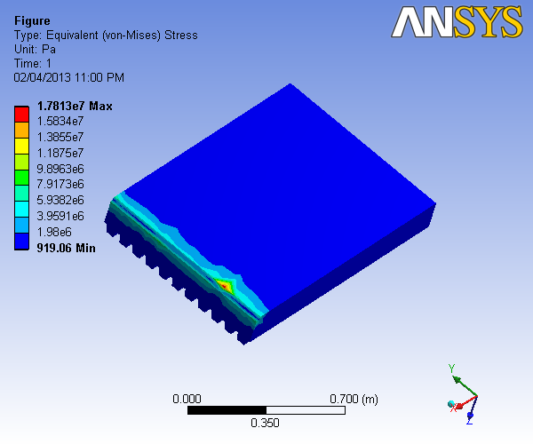 | Figure 5. Showing Swing Jaw Plate Stress Analysis |
 | Figure 6. Showing Swing Jaw Plate Displacement |
4. Swing Jaw Plates with Stiffeners
4.1. Solid Modeling of Swing Jaw Plates with Stiffeners
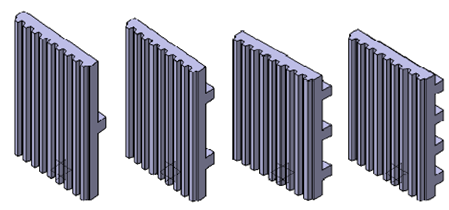
 | Figure 7. Solid Model of Corrugated Swing Jaw Plate with Stiffeners |
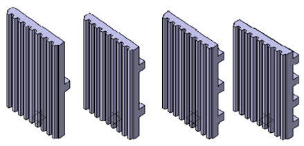 | Figure 8. Swing Jaw Plates (1200Χ900Χ140) with Stiffeners |
 | Figure 9. Jaw Plates (1200Χ900Χ152) with Stiffeners |
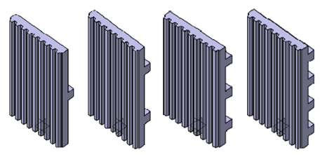 | Figure 10. Swing Jaw Plates (1200Χ900Χ165) with Stiffeners |
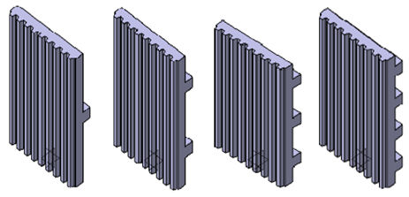 | Figure 11. Swing Jaw Plates (1200Χ900Χ178) with Stiffeners |
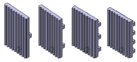
 | Figure 12. Swing Jaw Plates (1200Χ900Χ191) with Stiffeners |
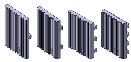
 | Figure 13. Swing Jaw Plates (1200Χ900Χ203) with Stiffeners |
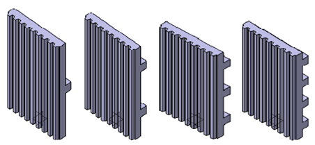
 | Figure 14. Swing Jaw Plates (1200Χ900Χ216) with Stiffeners |
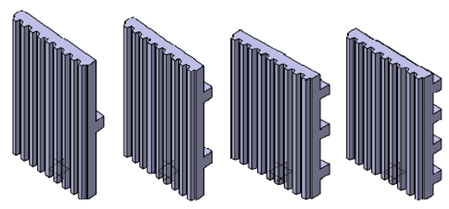 | Figure 15. Swing Jaw Plates (1200Χ900Χ224) with Stiffeners |
5. Swing Jaw Plates Static Stress Analysis
5.1. With Stiffeners
Below is a finite element representation of the stiffened plate shown above. The plate is thick, therefore thick plate theory applies. Square beam stiffeners are mounted as shown. The structure is simply supported and point loads at applied to the surface of the plate.
5.2. Apply Boundary Conditions
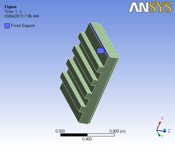 | Figure 16. Showing Stiffened Swing Jaw Plate Boundary Condition |
Table 1.
 |
| |
|
5.3. Applying Load
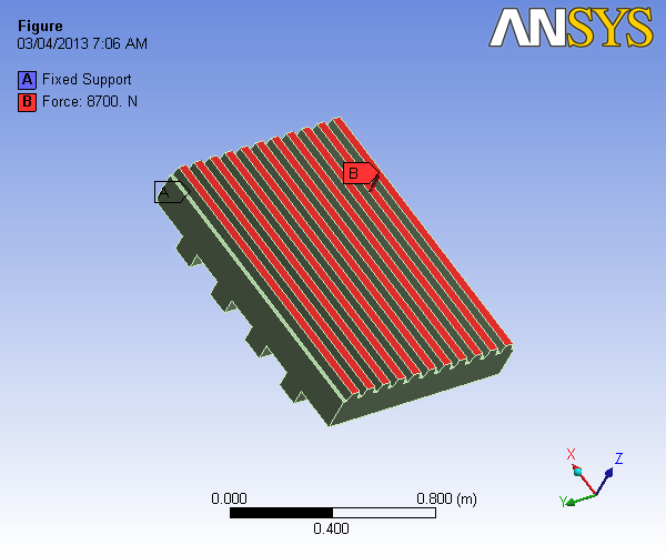 | Figure 17. |
5.4. Linear Static Stress Analysis Results
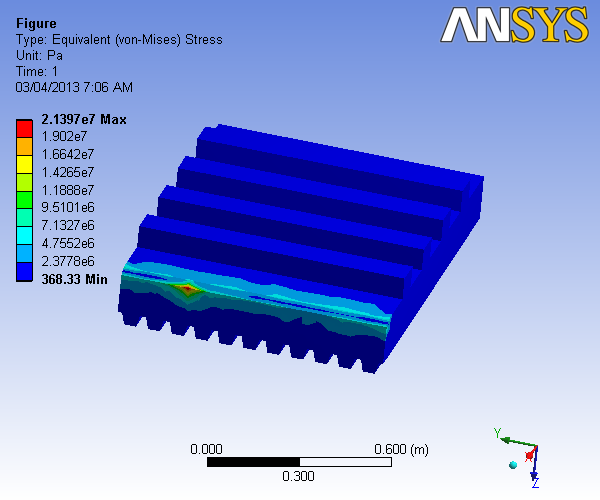 | Figure 18. Showing Stiffened Swing Jaw Plate Stress Analysis |
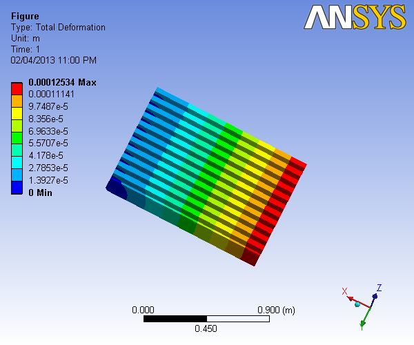
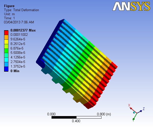 | Figure 19. Showing Stiffened Dispacement Swing Jaw Plate |
6. Results and Conclusions
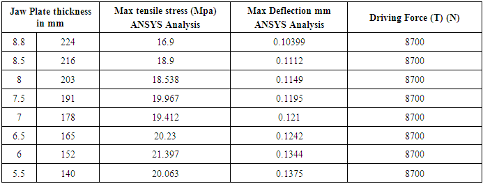
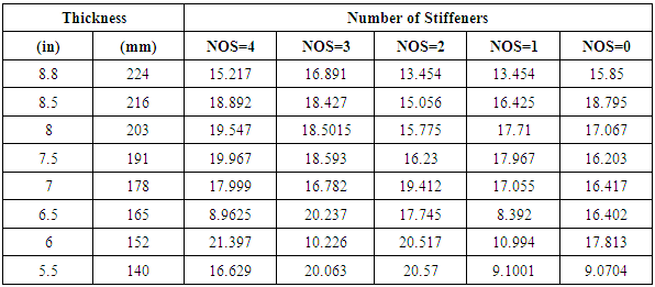
FEA models using ANSYS are employed to calculate maximum tensile stresses for a variety of model plate thicknesses.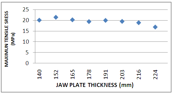 | Figure 20. Maximum Tensile Stress Response for Various Jaw Plate Thicknesses |
Table 2. Effect of stiffeners on maximum response for various jaw plate thicknesses
 |
| |
|
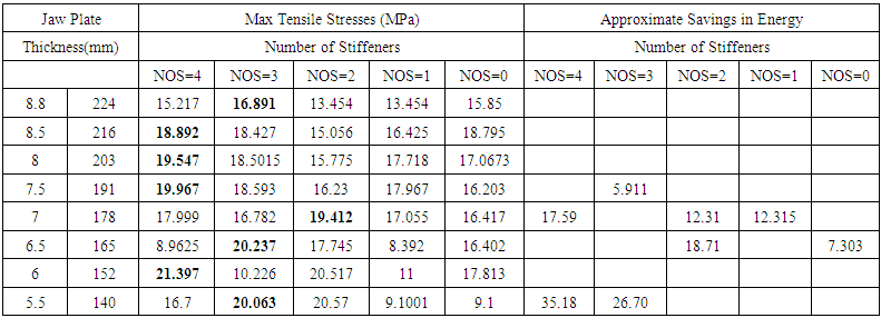 | Table 3. Comparison of Various Jaw Plates with and without stiffeners |
6.1. Approximate Savings in Energy using Stiffeners
If fatigue of the plate is of concern, then the maximum tensile stress is important. The maximum induced tensile stress for the 216 mm thick model plate equals that induced for the 140 mm plate. This difference is found because the particles do not fail simultaneously but fail at different stages, of a single crushing cycle. If the peak acceleration (a) of the 203mm and 152 mm plates is assumed to be equal, then the force reduction resulting from a smaller plate is proportional to the acceleration times the change in plate mass. Since the mass is somewhat proportional to the thickness of the 216 and 140 mm models, the crushing energy absorbed by plate movement is reduced by approximately [(216 – 140)/216] = 35%. Of course this 35% is an estimate, as the model plates which are stiffened and leads to reductions in plate weight and indicates that design of new energy efficient systems should include deformation (PDF) properties of the crushed material.
7. Conclusions
The stiffened plate models which leads to reductions in plate weight and indicates that Design of new energy- efficient systems of the crushed material. Thus stiffness of swing plate is enough to crush taconite with an unconfined compressive strength (QU) of up to 308 MPa, may be over signed for softer fragmental. Hence the weight of the swing plate is necessary to reduced. In this paper work can be done with help of Point-Load Deformation Failure (PDF) relationship along with interactive failure of rock particles. Design of a plate is carried by using CATIA software. In case stiffened jaw plates as the number of stiffener increases the strength/weight ratio of the jaw plate increases making it stronger than that of without stiffener. The stiffened plate models which leads to 35% saving in energy, of course this 35% is an estimate.
ACKNOWLEDGEMENTS
The authors gratefully acknowledge the MHRD New Delhi for financial support under Centre for Energy and Resources Development (CERD) to perform this study.
References
| [1] | DeDiemar R.B. “New concepts in Jaw Crusher technology”, Minerals Engineering, Volume 3, Issues 1-2, 1990, Pages 67-74. |
| [2] | Russell A.R., Wood D. M. “Point load tests and strength measurements for brittle Spheres”, International Journal of Rock Mechanics and Mining Sciences, Volume 46, Issue 2, February 2009, Pages 272-280. |
| [3] | Dowding Charles H, Molling R, Ruhl C," Application of point load-deformation relationships and design of jaw crusher plates”, International Journal of Rock Mechanics and Mining Sciences & Geomechanics, Volume 20, Issue 2, April 1983,Pages 277-286. |
| [4] | Gupta Ashok, Yan D.S. “Mineral Processing Design and Operation-An introduction”, Published by Elsevier, 2006, Pages 99-127. |
| [5] | Bharule Ajay Suresh, Computer aided design and Analysis of Swing Jaw Plate of Jaw Crusher, NIT Rourkela, 1-11, 2009. |
| [6] | Computer Aided design of Jaw Crusher” by Sobhan Kumar Garnaik NIT Rourkela, 1-11, 2009-10. |
| [7] | Niles I. L., “MS Thesis -Point Load Strength: Jaw Crusher Design”, August, 1978. |
| [8] | Pollitz H C, “Crusher Jaw Plates” United States Patent, Patent Number 3,140,057, Issued on July, 1982. |
| [9] | Cao Jinxi, Qin Zhiyu, Wang Guopeng, “Investigation on Kinetic Features of Multi-Liners in Coupler Plane of Single Toggle Jaw Crusher”, Journal of Taiyuan Heavy Machinery Institute, July 200. Pages 210-219. |
| [10] | Yashima Schimum, “Analysis and Optimization of Crushing Energy of a Compound Swing Jaw Crusher”, Journal of Taiyuan Heavy Machinery Institute, March 1995, Pages 188-192. |

 Abstract
 Reference
 Full-Text PDF
 Full-text HTML