A. Tripathi 1, M. Dubey 2, H. Chandra 3, Anil Kumar 3
1Automobile Engineering Department, RJIT, BSF Academy Tekanpur, Gwalior, India
2Mechanical Engineering Department, V.E.C Lakhanpur, Sarguja University, Ambikapur, India
3Mechanical Engineering Department, Bhilai Institute of Technology, Durg, India
Correspondence to: A. Tripathi , Automobile Engineering Department, RJIT, BSF Academy Tekanpur, Gwalior, India.
| Email: |  |
Copyright © 2016 Scientific & Academic Publishing. All Rights Reserved.
This work is licensed under the Creative Commons Attribution International License (CC BY).
http://creativecommons.org/licenses/by/4.0/

Abstract
In this paper, thermal modeling for the performance evaluation of gas turbine cogeneration system with reheat is presented. The total useful energy rate has been analyzed for Joule-Brayton cogeneration reheat cycle and the efficiency at the maximum total useful energy rate is also determined. It has been found that the dimensionless total useful energy rate and the corresponding thermal efficiency decrease with the increase of power to heat ratio. The inclusion of reheat significantly improves the overall performance of the cycle. This methodology may be quite useful in the selection and comparison of combined energy production systems from the thermodynamic performance point of view.
Keywords:
Brayton cycle, Cogeneration, Total useful energy rate, Thermal efficiency, Finite time thermodynamics
Cite this paper: A. Tripathi , M. Dubey , H. Chandra , Anil Kumar , Thermodynamics Performance Analysis of Reversible Reheat Joule–Brayton Cycle with Cogeneration System, International Journal of Energy Engineering, Vol. 6 No. 1A, 2016, pp. 1-6. doi: 10.5923/s.ijee.201601.01.
1. Introduction
Thermal efficiency of real heat engine could not exceed beyond Carnot efficiency while working between same heat source and sink temperature respectively, this is due to the fact that all the processes in a Carnot cycle are completely reversible and executed at a very slow process. Since the reversible Carnot cycle was proposed in 1824, its thermodynamics efficiency has been used as a standard for all real heat-engine efficiencies. The maximum output power and efficiency for the endoreversible Carnot cycle by considering the external irreversibility due to finite temperature difference between the heat cycle and the external reservoirs, lading to new branch of finite time thermodynamics in 1975, investigated by Curzon and Ahlborn [1]. However the basic idea about FTT was initiated by Chambadal [2] and Novikov [3], such was followed and derived by Curzon and Ahlborn [1] for Carnot cycle. For evaluating the power output and thermal efficiency of thermodynamic cycle finite time thermodynamics (FTT) is more practical than the classical thermodynamics. In recent decade, many important works related to Carnot, Brayton, Rankine, Stirling, Ericsson power cycle applying theory of finite time thermodynamic have been published [2-15]. Thermodynamic performances of various Brayton cycles have been widely analyzed and optimized using finite time thermodynamics [5-6]. The Curzon and Ahlborn efficiency is equal to the efficiency of reversible Joule-Brayton heat engine, operating at the maximum power output given by Leff [10].Few researchers have obtained quite effective results using FTT for performance analysis of cogeneration plants. Combined heat and power (CHP) or Cogeneration is the simultaneous production of electricity and usable heat. A unified comparison method for the calculation of thermodynamic efficiency applied to CHP plant have presented by Athanasovici, et al. [11]. The new thermodynamic criterion for analyzing the efficiency of a cogeneration plant is proposed by Feng et al. [12], which can also be used for cost optimization of CHP systems. The exergy optimization for endoreversible Carnot cogeneration cycle is performed by Sahin et al [13]. Using FTT, they also determined the optimum values of the designed parameters of the cogeneration cycle at maximum exergy output.More complex system such as reheat combined heated power may be needed to achieve better thermodynamic performance. If reheat is employed, a more powerful production and higher turbine exhaust temperature will result [14]. In industry, the open-cycle Brayton heat engines are mostly used. It is a good way for improving energy utilization efficiency to achieve the combined production of power and heat.The cogeneration system with reheat has not been analyzed as much as the simple cogeneration system that has been seen from the literature survey. Only few papers have been published focusing on thermodynamic analysis of combined energy production with reheat. However, the optimization of the Joule-Brayton power cycle obtained by previous researchers, which mainly focused on the power output characteristics of the cycle, may not be optimal for cogeneration purposes. Therefore, it is required to optimize cogeneration plant as whole. To obtain useful power output and heat output is the purpose of cogeneration plant, which is different from the power plant, therefore, in this paper a new criterion of total useful energy rate of a reversible reheat Joule-Brayton cycle for cogeneration is carried out.
2. Methods
2.1. Theory and System Description
Figures 1 and 2 show the schematic and T-s diagram of a Joule-Brayton reheat cogeneration cycle with reheater respectively. The basic components of Joule-Brayton reheat cogeneration cycle are compressor (C), combustion chamber (CC) or heater (H), high pressure turbine (HPT), reheater, low pressure turbine (LPT) and heat exchanger (HE). 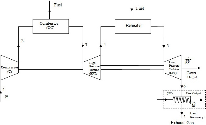 | Figure 1. Schematic diagram of Joule-Brayton reheat cogeneration cycle |
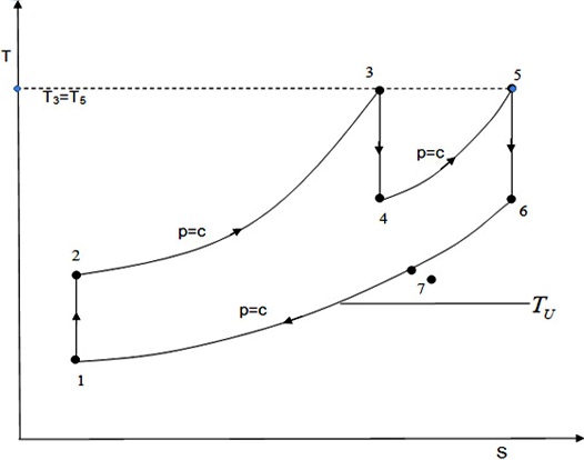 | Figure 2. T-S diagram of Joule-Brayton reheat Cogeneration cycle |
At state 1 the gas enters in a compressor and is compressed up to state 2 isentropically. State between 2 to 3 the isobaric heat addition process takes place in the combustion chamber and the compressed gas enters the turbine at state 3 and expands isentropically up to state 4. The isobaric heat addition process takes place between state 4 to 5 in the reheater after the hot gas leaves from HPT. After that the gas enters the LPT at state 5 and expands up to state 6 isentropically. Use a heat Recovery system between state 6 to 7 before rejecting heat to the heat sink, thus completing the cycle. Any irreversibility caused by flow, heat transfer, and combustion are not considered therefore the Joule-Brayton power cycle is strictly reversible model. The output of Joule-Brayton reheat engine is a useful work for user and rejects the waste heat to the ambient environment. The Joule-Brayton reheat engine reduces the consumption of fuel, waste heat in the exhaust gas, so cogeneration of power and heat is obtained. However to obtain a certain amount of heat flow from the cycle, the external irreversibility caused by heat transfer across a finite time temperature difference must be present. Therefore, this cycle is called as endoreversible Joule-Brayton Reheat Cogeneration cycle.
2.2. Thermodynamics Analysis and Performance Parameters
The power of a Joule-Brayton reheat cogeneration cycle can be written as: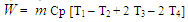 | (1) |
The useful heat flow rate is: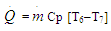 | (2) |
The total useful energy rate (TUER) of the cogeneration cycle is defined as the sum of power and useful heat output: | (3) |
The relevant parameters required for the evaluation of thermodynamics performance of cogeneration reheat cycle is the pressure ratio parameter which is given by: | (4) |
While the cycle temperature ratio is given by: | (5) |
Assuming that there is a minimum temperature required by the thermal energy consumer (TU), called the user’s temperature ratio and defined as: | (6) |
The potential of waste heat in the exhaust gas which can be recovered for useful purpose can be defined as:  | (7) |
Using the adiabatic relation of an ideal gas for the reversible Joule-Brayton cycle and substituting Eqs. (4-7) into Eqs. (1-3), yields: | (8) |
 | (9) |
 | (10) |
Introducing new term power to heat ratio, of the cycle (R) is defined as: | (11) |
And substituting Eq. (8) and (9) into Eq. (11), yields: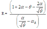 | (12) |
The performance of the cogeneration cycle has a great effect on the heat to power ratio (R) and it is constrained by the user’s requirement for power and heat. Thus using Eq. (12), yields: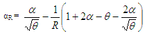 | (13) |
It is not difficult to find that αR and θ which is constrained by the following inequality,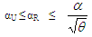 | (14) |
Substituting Eq. (13) into Eq. (10) yields: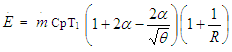 | (15) |
Considering the fuel energy consumption F of the cogeneration cycle, this can be computed by: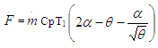 | (16) |
Introducing the dimensionless total useful energy rate (Ē) which is obtained by dividing Ė by mCpT1, for a constant specific heat and a fixed ambient temperature (T1), yields: 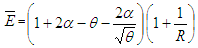 | (17) |
The efficiency of the Joule-Brayton reheat cogeneration cycle is given by: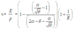 | (18) |
3. Results and Discussion
Data for all the input parameters are taken from Hao and Zhang [15] for the analysis purpose. Fig.3 shows the variation of dimensionless total useful energy rate,  with respect to pressure ratio parameter, θ, for various power-to-heat ratios, R, for constant cycle temperature ratio, α. From this figure it has been observed that the maximum DTUER increases with decreasing value of R. This decreases in R, increases heat recovery from heat exchanger. This figure also shows that
  is increase with θ up to an optimum point, after that it is decrease by increasing θ.
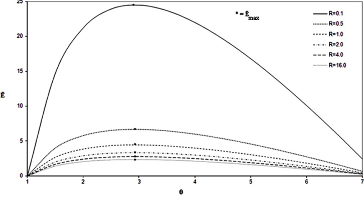 | Figure 3. Variation of Ē, with respect to θ for various values of R (α = 5.0) |
The variation of efficiency given in Eq. (18) with respect to the pressure ratio parameter (θ), for various power-to-heat ratios (R), for a constant cycle temperature ratio (α), is shown in Fig.4, from which it has been indicated that the maximum efficiency decreases with increasing the value of power to heat ratio. It is very clear that the decrease in heat utilization from heat exchanger causes an increase in value of R. It is due to the fact that the total useful energy rate decreases and simultaneously efficiency also decreases. This figure also indicates that the increase in value of θ, the value of η increases up to a certain point after that it decreases.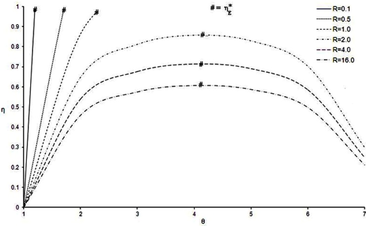 | Figure 4. Variation of η with respect to θ for various values of R (α=5.0) |
The effect of reheat on performance parameter is also shown in Fig. 3-4. It has been observed from the result that for the same input parameter, taken from reference [15], inclusion of reheat gives significant improvement in DTUER  efficiency (η), as compared to the work of Hao and Zhang [15].
4. Conclusions
The Joule-Brayton reheat cogeneration cycle based on total useful energy rate has been analyzed. The effects of power to heat ratio, cycle temperature ratio, and user temperature ratio on the optimum value total useful energy rate and the corresponding efficiency at maximum TUER have been assessed. It is found that the power to heat ratio increases, the maximum total useful energy rate decreases. Reheat expansion gives significant improvement in DTUER, and efficiency, which will be useful in obtaining the important thermodynamic information for proper trade offs in the comparison and selection of cogeneration systems.
Nomenclature
Cp = Constant pressure specific heat (kJ/kg-K)Cv = Constant volume specific heat (kJ/kg-K) = Dimensionless total useful energy rate (DTUER)E = Total useful energy rate (TUER) (kW)F = Fuel energy consumption (kW)
 = Mass flow rate of air (kg/s)P1 = Pressure at inlet to the compressor (N/m2)P2 = Pressure at outlet to the compressor (N/m2)P4 = Intermitted pressure (N/m2)
 = Heat flow rate (kW)R = Ratio of power to heatT1 = Inlet temperature at compressor (K)T2 = Temperature at inlet to combustion chamber (K)T3 = Temperature at inlet to the high pressure turbine (K)T4 = Temperature at outlet to the high pressure turbine (K)T5 = Temperature at inlet to the low pressure turbine (K)T6 = Temperature at outlet to the low pressure turbine (K)T7 = Temperature at outlet of heat exchanger (K)TU = Useful temperature (K)
 = power (rate of work) (kW)Greek lettersα = Cycle temperature ratioαR = Recovery temperature ratioαU = Useful temperature ratioθ = Pressure ratio
 η = Efficiency
References
| [1] | F.L. Curzon, B. Ahlborn, 1975, Efficiency of a Carnot engine at maximum power output, Am. J. Phys. 43(1), 22–24. |
| [2] | P. Chambadal, 1957, Les Centrals Nucleaires, Armand. Colin Paris, 41-58. |
| [3] | I. I. Novikov, 1958The efficiency of atomic power stations, J. of Nuclear Energy II (17), 125-128. |
| [4] | A. Durmayaz, O.S. Sogut, B. Sahin, H. Yavuz, 2004, Optimization of thermal systems base via finite-time thermodynamics and thermo economics, Prog. Energ. Combust, 30, 175–217. |
| [5] | A. Bejan, 1996, Entropy generation minimization: the new thermodynamics of finite-size devices and finite-time processes, J. Appl. Phys. 79(3), 1191–1218. |
| [6] | K. Lucas, 2000, On thermodynamics of cogeneration, I. J. of Thermal Sci., 39, 1039–1046. |
| [7] | C.Y. Cheng, C.K. Chen, 1998, Efficiency optimizations of an irreversible Brayton heat- Engine, Trans. ASME J. Energy Res. Tech. 120(2), 143–148. |
| [8] | B. Sahin, A. Kodal, T. Yilmaz, H. Yavuz, 1996, Maximum power-density analysis of an irreversible Joule–Brayton engine, J. Phys. D: Appl. Phys. 29, 1162–1167. |
| [9] | C. Wu, 1991, Power optimization of an endoreversible Brayton gas-turbine heat engine. Energy Convers. Mgmt., 31(6), 561–565. |
| [10] | H.S. Leff, 1987, Thermal efficiency at maximum work-output: new results for old heat engines. Am. J. Phys. 55(7), 602–610. |
| [11] | V. Athanasovici, O. Le Corre, G. Brecq, M. Tazerout, 2000, Thermo-economic analysis method for cogeneration plants, Proc. of ECOS, Netherlands, 157–164. |
| [12] | X. Feng, Y.N. Cai, L.L. Qian, 1998, A new performance criterion for cogeneration system, Energy Convers. Mgmt. 39 (15), 1607–1609. |
| [13] | B. Sahin, A. Kodal, I. Ekmecki, T. Yilmaz, 1997, Exergy optimization for an endoreversible cogeneration cycle, Energy, 22(5), 551–557. |
| [14] | I.G. Rice, 1980, The combined reheat gas turbine/steam turbine cycle Part I––A critical analysis of the combined reheat gas turbine/steam turbine cycle, ASME J. of Engg. Power, 102, 35–41. |
| [15] | X. Hao, G. Zhang, 2007, Maximum useful energy rate analysis of an endoreversible Joul-Brayton cogeneration cycle, I. J. of Appl. Energy, 84, 1092-1101. |

 Abstract
 Reference
 Full-Text PDF
 Full-text HTML