-
Paper Information
- Next Paper
- Previous Paper
- Paper Submission
-
Journal Information
- About This Journal
- Editorial Board
- Current Issue
- Archive
- Author Guidelines
- Contact Us
Computer Science and Engineering
p-ISSN: 2163-1484 e-ISSN: 2163-1492
2015; 5(1A): 1-7
doi:10.5923/s.computer.201501.01
Partial Image Secret Sharing Using Discrete Wavelet Transform
 Abstract
 Reference
 Full-Text PDF
 Full-text HTML
Abdelnaser Rashwan , Honggang Wang
Electrical and Computer Engineering Department, University of Massachusetts Dartmouth, North Dartmouth, MA
Correspondence to: Honggang Wang , Electrical and Computer Engineering Department, University of Massachusetts Dartmouth, North Dartmouth, MA.
| Email: |  |
Copyright © 2015 Scientific & Academic Publishing. All Rights Reserved.
It is challenging to apply secret image sharing schemes for image transmission over wireless networks. Many of the existing secret images sharing schemes do not pay much attention to the relationship between the share size and share transmission. To reduce a share size and protect the image transmission, we propose a secret sharing scheme that uses a Discrete Wavelet transform (DWT) decomposing an image into low frequency and high frequency bands. Our proposed scheme can be applied in each frequency band individually to produce shares. Since the low frequency band has the significant coefficients of the image, in case of a share transmission over a lossy wireless channel, redundant shares are only taken from the low frequency bands to mitigate the loss in the reconstructed image. Since the I-frame in MPEG codec is the most significant frame and all other frames in the video sequence are referenced to it, we apply our secret scheme in this frame to secure video sequence. We use our simulation to prove the efficiency of the proposed schemes.
Keywords: Secret images sharing, Discrete Wavelet transforms
Cite this paper: Abdelnaser Rashwan , Honggang Wang , Partial Image Secret Sharing Using Discrete Wavelet Transform, Computer Science and Engineering, Vol. 5 No. 1A, 2015, pp. 1-7. doi: 10.5923/s.computer.201501.01.
Article Outline
1. Introduction
- With the fast development of various types of communication networks, there is an increasing demand to secure the data transmission. Users want to keep their data secure from unauthorized users. This always requires using some encryption techniques such as data hiding and steganography. However, many of these protection schemes are not designed for the image transmission over wireless networks. If an unauthorized user obtains the encryption key, then it will become easy for him/her to obtain an access to the whole data of interest. Moreover, saving sensitive information in just one storage node would not be efficient if that node is subject to physical damage.Secret image sharing schemes have been implemented to protect secret images from being compromised. Secret sharing schemes have an advantage over the aforementioned schemes where in secret sharing schemes, even if the unauthorized user has access to some data, he/she will not be able to decrypt the whole data of interest.Shamir [1] first hypothesized the secret sharing. The author named his new approach the (T, N) threshold scheme. The threshold scheme splits the secret data into small pieces called “shares”. The secret data could be only reconstructed by using a number of shares no less than a defined threshold T. In [11] Brinkman et al. have suggested a secret sharing scheme to look for the image contents in encrypted data. It is also shown how to securely retrieve the image at receiver using Shamir. Bai [2] also suggested a scheme by using matrix projection with Shamir’s scheme. Lately, Wang et al. [3] proposed an incrementing visual cryptography by employing random grids. Chen and Tsao [4] designed a threshold RG-based on visual secret sharing scheme. To reduce the share size, Thein and Lin [3] suggested numerical processing procedures to share a secret image secretly where they initially permute an image into random image and then shares. Shares are generated using a secret sharing approach proposed by Shamir. They succeeded in reducing the share size to 1/T of the original image. In [15], Huffman code was used to reduce the share size. In addition, there are some research works using the secret sharing for secure data transmission. However, they did not pay attention to the secret sharing sensitivity to errors and how that packet loss could degrade the reconstructed image quality.In terms of multimedia encryption, many encryptions schemes are proposed to protect the video [6] [17]. In [11], Qiao and Klara suggested splitting a group of I-frame packets into two parts and then both parts are XORed and saved in one part. The other part was encrypted with Data Encryption Standard (DES). In [10], Chen improved this scheme by changing the permutation range from a segment to a frame. Chen also proposed to divide each DCT macro-block into 64 groups according to their positions, and scrambled them within each group. In [16], the authors proposed to design secret sharing based on the DC coefficients and AC coefficients. However, it is very challenging to apply these schemes in real-time image streaming application when the image or video size is large. There are many existing works for multimedia transmission over networks [18-23]. In these works, the transmission quality and network quality of service are major goals.As we mentioned earlier that secret sharing schemes are sensitive to channel errors because losing one pixel in a share results in losing T pixels in the reconstructed image. To combat this quality degradation in the reconstructed image, redundancy will be needed and with rate higher than redundancy in traditional encryption schemes. It is clear that high redundancy is not efficient if these schemes are used in resource constraints systems. For this reason, we adopt a discrete wavelet transform (DWT) to reduce the redundancy size by shrinking the size of the shares where the secret image is transformed by DWT to pro-duce one low frequency band and three high frequency sub-bands. Then, Thein and Lin’s scheme can be applied in each band separately to produce shares for each sub-band. The redundant shares would be only transmitted from the low sub-band because it has the most significant coefficients of the image. By this way, we ensure that the redundant shares size decreases and many resources (i.e., energy, bandwidth) can be reduced. Obviously, small share size also adds some flexibility to the framework in terms of transmission speed. Experimental results show that the proposed scheme successfully decreases the shares size while providing the same image quality at the same level as the Thein and Lin’s scheme. Decoding the Inter-frames (P-frames, B-frames) in the video sequence cannot be achieved without successful decoding of Intra-frame (I-frame). Therefore, we suggest securing the video sequence by applying secret image sharing only on the I-frame to produce the shares. The inter-dependency between the I-frame and inter-frame (P-frame, B-frame) is exploited to develop a video quality metric based on secret image sharing.The remaining sections are organized as follows. A brief review of Thien and Lin's scheme is given in section 2. In Section 3, the proposed work will be described in details. We discuss the experimental results in Section 4. Finally, Section 5 concludes this paper.
2. Thien and Lin’s Scheme
- Thein and Lin scheme generated N shares by splitting the secret image (main image) into
 non overlapping T blocks, each block is represented in the corresponding shares representation as shown below:
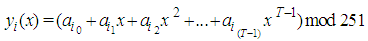 | (1) |
 indicates the share pixel connected with
  block in the share image, for
  and
and  . The value of
  is obtained using the original pixel values that are contained in the
  block. Truncating the values of the share pixels by dividing every pixel by 251(251 is the largest prime number in the uint8 gray image). Because the degree of the polynomial is chosen to be T-1, the size of share is 1/T of the secret image. To reconstruct the secret image, The polynomial in Eq.(1) can be retrieved by Lagrange interpolation. Repeating these procedures for all shares pixels reconstruct the secret image.
3. Partial Image Secret Sharing
- Most of the existing secret images sharing schemes did not pay attention to share transmissions over wireless networks. The question here is: if the shares are received with some distortion, can uses still be able to reconstruct the original image? A corrupted share means that there are some distorted pixels in the share. In Fig.1, a secret matrix A is divided into three shares by using a secret threshold (T=3, N=3). This threshold indicates that the polynomial will be with a degree of 2. Therefore, three points are needed to define this polynomial. When one of the three points is lost, it becomes impossible to derive the polynomial formula.
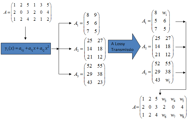 | Figure 1. An example of distorted shares |
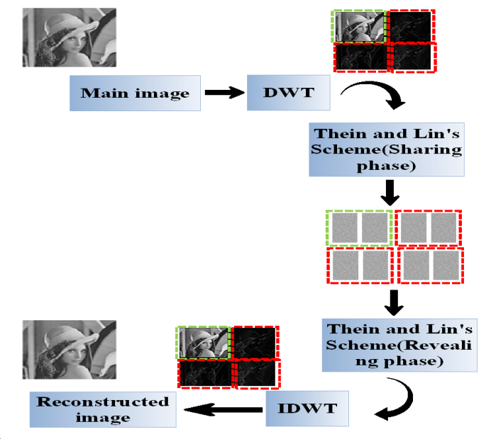 | Figure 2. The proposed secret image sharing scheme |
3.1. Sharing Procedures
- The sharing procedures can be described as follows:• The secret image is passed through discrete wavelet transform.• In this phase, the
 threshold and the
  degree of sharing functions are firstly decided. The
  degree polynomial sharing function can be constructed by Eq. (1).• Assume that
  and
and  are determined so that a secret image
  is shared by
  shares
 . A number of
  or higher is required to reveal secret image
  by using Lagrange’s interpolation formula. The pixel values
  for each share are obtained from Eq.(2).
 | (2) |
 are separately assigned to
  shares
 3.2. Revealing Phase
- The revealing phase can be described as follows:• Suppose
 shadows
  are collected and pixels values
  are derived from the collected shadows so that sharing functions
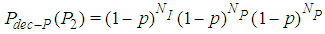
 can be reconstructed by Lagrange’s interpolation formula.• We keep repeating step (1) until we process all the pixels in the share images.• By completion step (2), we obtain the permuted image. Therefore, the inverse permutation has to be applied to obtain the compressed secret image.• The inverse-discrete wavelet (IDWT) is applied on the resulted image to get the secret image.For video encryption, our partial image secret sharing scheme is only applied on the I-frame because I-frame is the most significant frame in a Group Of Picture (GOP). Encrypting the I-frame is equivalent to encrypting the rest of the frames (i.e., P-frames) in the GOP. As a result, it would be impossible for an eavesdropper to obtain any information about the video sequence even if all the P-frames and B-frame are compromised. Here, we develop a video model to estimate the video quality of our proposed scheme. It is known that the video quality can be estimated with different metrics such as Peak Signal-to-Noise Ratio (PSNR), the Structural Similarity index (SSIM), Moving Pictures Quality Metric (MPQM) and decodable frame rate (Q). In this paper, we use the decodable frame rate (Q) which is defined as the ratio between the numbers of successfully decoded frames to the total number of the frames sent.
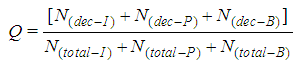 | (3) |
 , where
  defines the GOP length (i.e. the total number of frames within each GOP) and
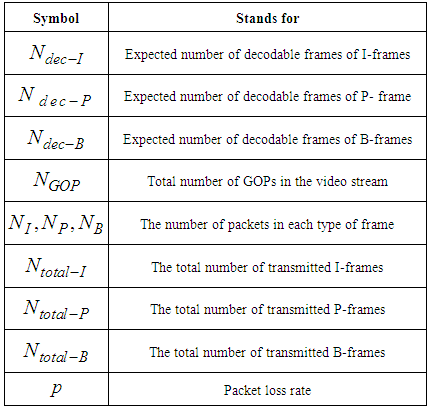
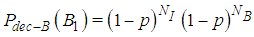
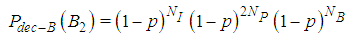
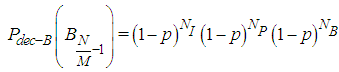
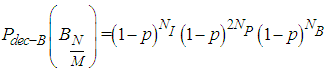
  is the number of B frames between I-P or P-P frames. For example as illustrated in Fig.3, (7,2) means that the GOP consists of one I-frame, two P-frames, and four B-frames. The second I-frame marks the beginning of the next GOP. The arrows indicate that the successful decoding of B and P-frames depends on the neighboring I or P-frames. The received packets usually suffer partial loss or total loss. Lost packets not only affect the frame to which they belong, but also they affect all the frames that have dependency on that frame. In other words, the error propagating from one frame to another, significantly degrade the quality of the whole video sequences.Generally speaking, once the transmitter has a video sequence to be sent, every frame of the video sequence is split into a number of packets with size less or equal to the allowed maximum packet of the underlying network. The frames are reconstructed at the receiver if the number of decoded packet exceeds a threshold called the decodable threshold (DT). Table(1) shows the notation in this paper.
|
 | (4) |
 | (5) |
 | (6) |
 | (7) |
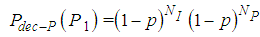
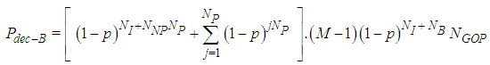
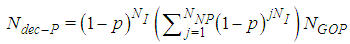
 represents the number of P-frames which in the case of GOP (N=7, M=2) is equal to 3. The expected number of successfully decoded P-frames for the whole video is calculated by:
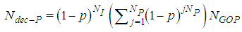 | (8) |
 | (9) |
 | (10) |
 | (11) |
 | (12) |
 | (13) |
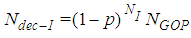
 . After applying
  secret sharing scheme, the number of I-frames is increased to:
 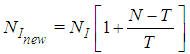 | (14) |
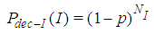
 .Then, the probability of receiving at least
  packets from
  is
is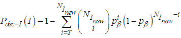 | (15) |
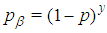 . It represents the probability of receiving
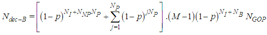
  bits unharmed. Then the expected number of correctly decoded I-frames for the entire video is:
 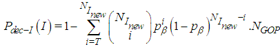 | (16) |
 | (17) |
 | (18) |
4. Experimental Results and Security Analysis
- The performance of the proposed scheme is validated by the experiments. All the test images are taken from the USC-SIPI image database [14]. Two images ‘Lena’, ‘Boat’ with 512×512 pixels are used in the following experiments. These schemes have been implemented by Matlab. For the first experiment, Four and five shares from each band are produced by (2, 4) and (4, 5) respectively. The visual quality of the reconstructed images (i.e., PSNR value) are recorded. As we can see in the Fig.3 (a), the quality of the reconstructed image is excellent with very small loss due to the compression loss. We also compare the average PSNR of the new scheme and scheme of Thein and Lin’s scheme [3]. Thresholds (T=2, N=2) and (T=4, N= 4) have been applied on Lena image and the generated shares are transmitted over a lossy channel. In the scheme, DWT is not applied and no redundant shares are sent over the erasure channel.
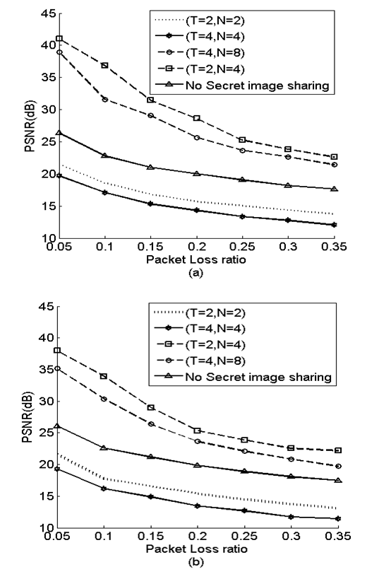 | Figure 3. (a)Thein and method’s scheme. (b) proposed scheme |
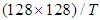 .In the third experiment, redundant shares have been transmitted to enhance reconstructed image quality. The schemes after adding redundant shares would be (T=2, N=4) and (T=4, N=8), respectively. The image quality has been improved as it is illustrate in Fig. 4(a). However, the redundant factor (r) for each one of these scheme is 2. This means that the number of shares has been increased to twice its original number, which is quite high and not efficient if these schemes are employed in limited resource networks. In the last experiment, DWT divides the image into four bands, and each band with size
  . Redundant shares are only taken from the low frequency band.
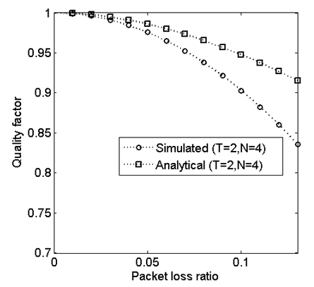 | Figure 4. Testing the proposed video metric |
 . Thus, the redundancy factor has been reduced with 0.75 compared to Thein and Lin’s scheme. Moreover, the proposed scheme gives PSNR close to Thein and Lin’s scheme as illustrated in Fig.3 (b). The small difference in the reconstructed image between the two schemes happens due to DWT compression loss. A polynomial function with degree
  requires at least
  values to be reconstructed. In other words, at least any
  shares are needed to reveal all sharing functions with the Lagrange interpolation formula. If an unauthorized user has
  shares and desires to construct all sharing functions, there will be
  ,
, stands for the number of sharing functions in all shares and
  is the pixel value. To reconstruct a sharing function, an attacker must correctly estimate all coefficients for a sharing function. In our scheme, the probability of obtaining the correct coefficient in the sharing function is
  and that is only for one polynomial, but there are
  polynomials need to be solved for the coefficients. We have tested our analytical video quality metric for GOP (12, 3). It is observed from Fig.4 that analytical model performance is consistent with the simulation when the packet loss rate is slight. Then it diverges as the packet loss rate increases. The reason is that the analytical model does not consider error concealment at the decoder side while the simulation model includes error concealment technique. For small rate packet loss, there is no significant packet loss to be concealed so that both models provide close performance.
5. Conclusions
- In this paper, we proposed a partial secret sharing scheme where the secret image is transformed by DWT into one low frequency band and three high frequency bands. Then Thein and Lin’s scheme was applied in each band to generate shares. We investigated the issues of transmitting the shares over a lossy channel and proposed sending redundant shares of the low frequency band to mitigate the packet loss in the reconstructed image. Not just the proposed scheme succeeds in minimizing the redundancy significantly, but it also provides the same quality level as Thein and Lin’s scheme. Our proposed partial image secret sharing can be utilized to secure the video transmissions.
ACKNOWLEDGEMENTS
- This work was generously supported by the national science foundation through the awards, CNS#1429120 and CCSS#1407882. Any opinions, findings, and conclusions or recommendations expressed in this paper are those of the author(s) and do not necessarily reflect the views of the national science foundation.