-
Paper Information
- Previous Paper
- Paper Submission
-
Journal Information
- About This Journal
- Editorial Board
- Current Issue
- Archive
- Author Guidelines
- Contact Us
International Journal of Composite Materials
p-ISSN: 2166-479X e-ISSN: 2166-4919
2013; 3(6B): 71-79
doi:10.5923/s.cmaterials.201310.08
Investigation of Delamination Effects on Dynamic Behaviour of Composite Rotors
 Abstract
 Reference
 Full-Text PDF
 Full-text HTML
P. Kostka 1, M. Fidali 2, K. Holeczek 1, A. Langkamp 1
1Technische Universität Dresden, Institut für Leichtbau und Kunststofftechnik (ILK), Holbeinstraße 3, 01307 Dresden, Germany,
2Silesian University of Technology, Institute of Fundamentals of Machinery Design, Konarskiego 18a, 44-100 Gliwice, Poland
Correspondence to: P. Kostka , Technische Universität Dresden, Institut für Leichtbau und Kunststofftechnik (ILK), Holbeinstraße 3, 01307 Dresden, Germany,.
| Email: |  |
Copyright © 2012 Scientific & Academic Publishing. All Rights Reserved.
In this article, exemplary results of numerical and experimental modal analysis of glass fibre reinforced epoxy disc rotors with different configurations of introduced delamination are shown. The work aims at identification of relations between the size and through-thickness position of the delamination and resulting modal properties of disc rotors including several natural vibration frequencies and corresponding modeshapes. For this purpose a parametrised finite element model of the delaminated disc rotor was developed. This model was calibrated using natural vibration frequencies obtained from experimental modal analysis carried out on healthy and delaminated rotors. Modal properties for different delaminations were then identified by numerical modal analysis conducted with the simulation model. Qualitative relations regarding the sensitivity of particular modes to induced delamination are proposed. The formulated conclusions can be useful for the design of on-line Structural Health Monitoring systems for composite rotors.
Keywords: Laminate, Layered Structures, Modelling, Vibration, Delamination, Non-Destructive Testing
Cite this paper: P. Kostka , M. Fidali , K. Holeczek , A. Langkamp , Investigation of Delamination Effects on Dynamic Behaviour of Composite Rotors, International Journal of Composite Materials, Vol. 3 No. 6B, 2013, pp. 71-79. doi: 10.5923/s.cmaterials.201310.08.
Article Outline
1. Introduction
- Fibre and textile reinforced composite structures are typically characterised by outstanding specific strength and stiffness properties. Moreover, the composite-specific high design flexibility of the anisotropic mechanical properties enables construction of high speed rotors with considerable performance enhancement compared to rotors made of conventional materials[1]. Nevertheless, to ensure safe, economical and efficient operation of high speed rotating machinery equipped with such rotors, an implementation of reliable and cost-effective damage detection methods is still necessary[2].Currently developed Structural Health Monitoring (SHM) techniques for composite structures are mostly focused on detection of fatigue or impact-caused structural faults of non-rotating components[3-7]. Most of these techniques are based on the analysis of vibration signals obtained using either the external or structure-embedded sensors.Since any damage initiation in the rotor causes changes in the dynamic behaviour of the whole machine (Fig. 1), the damage-detection procedures typically consider changes of modal parameters, i.e. natural frequencies, mode shapes, and modal dampings[8-10].Systems which enable monitoring of rotating structures made of conventional materials have been already reported and validated[11-13]. However, application of such systems to high-speed composite rotors is very challenging due to numerous dynamic rotation-related dynamic phenomena like crack-breathing, dynamical mechanical stress redistribution or tension-bending coupling emerging due to damage. Some metrological problems while using embedded sensors resulting from the influence of centrifugal forces on readout accuracy as well as the transmission of measured signals to a stationary analyser need to be considered as well[14].A key issue in designing on-line SHM systems is the identification of the unequivocal diagnostic relations between features of measurable physical signals generated by the machine such as noise or vibration and the existing damage condition. Identification of the diagnostic relations requires from one side an application of appropriate and sufficiently accurate measurement systems and from other side signal processing and analysis methods which enable the determination of sensitive signal features.This paper presents numerical and experimental investigations of the influence of delamination on dynamic behaviour of composite disc rotors. Vibration modes described by modal parameters such as natural frequencies and mode shapes were considered as diagnostic features enabling the assessment of the structural condition. In order to identify the sensitivity of particular vibration modes to delaminations of different size and position, a finite element (FE) model was created and series of simulations were conducted. For the calibration and validation of the FE model, an off-line experimental modal analysis was conducted on several composite disc rotors.
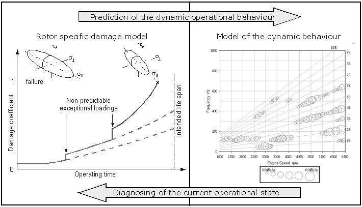 | Figure 1. Influence of material damage evolution on the rotor dynamic behaviour |
2. Investigation Procedure
- The damage presence in a composite structure causes, among others, a reduction of its dynamic stiffness resulting in alteration of natural frequencies and mode shapes[6]. Thus, the observation of these parameters of the structure during its operation offers the possibility of detecting the damage occurrence and its evaluation.The aim of the research was mainly to identify qualitative relations between through-thickness positions of delamination and modal parameters of composite disc rotors. This information can be useful for a further development of diagnostic methods for rotating composite structures.The proposed procedure involves the following steps:• manufacturing of composite disc rotors with and without introduced delamination,• experimental modal analysis of produced disc rotors,• design of a parametrised FE model of delaminated disc and its validation using experimentally obtained modal parameters,• conduction of numerical modal analysis for numerous configurations of delamination,• determination of regularities in numerical and experimental results caused by delamination.
3. Investigated Object
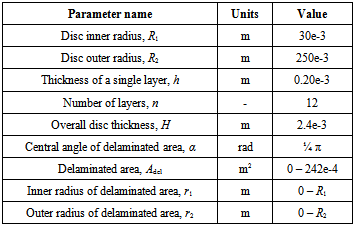
- The analysed object was a multilayered composite disc made of 12 glass fibre reinforced epoxy resin layers with and without introduced delamination. The stacking sequence of the disc was[0 / 60 / -60 / -60 / 60 / 0]S. Such arrangement of reinforcing fibres results in quasi isotropic in-plane properties of the structure.
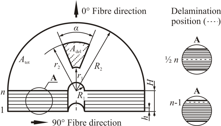 | Figure 2. General view of the investigated rotor and examples of the trough thickness delamination position |
|
|
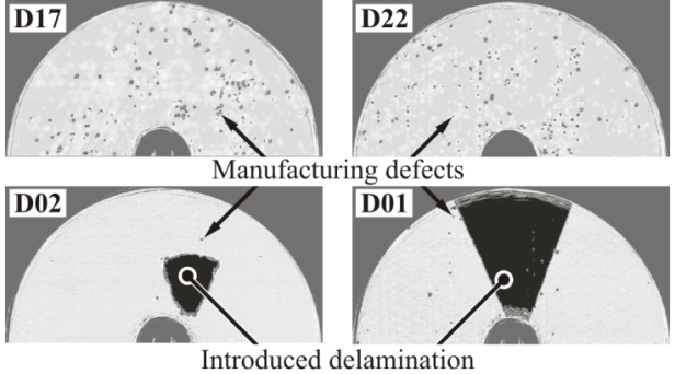 | Figure 3. Examples of ultrasonic scan images of manufactured discs |
4. Experimental Modal Analysis
- The aim of the experimental work was to determine the modal parameters of manufactured healthy and damaged rotors. This information provides the basis for the verification of the developed numerical model.
4.1. Experimental Set-up
- Experimental modal analysis was conducted using modal hammer as force exciter, and Laser Doppler vibrometer as vibration sensor. Such configuration of experimental set-up enables the determination of modal parameters with a minimal influence of transducers’ mass and simultaneously assures high measurement accuracy.The disc rotors were clamped in the centre with the use of a stiff clamping system. Every disc was excited with an impulse force signal in one fixed point (v. Fig. 4) using the modal hammer. The modal hammer was fixed to a revolute joint with a swing end stop mechanism in order to assure repeatable excitation force characteristics. The structural response was measured with the help of a single point Laser Doppler vibrometer in 32 regularly distributed measuring points as shown in Fig. 4.The force and velocity signals recorded using a triggered signal analyser were used to determine the frequency response function (FRF) in form of mobility calculated as velocity/force.The measurements were performed in the frequency range from 0 to 400 Hz with a frequency resolution of 0.25 Hz. An exponential window in the time domain was applied to the excitation and the response data and each FRF was averaged in the frequency domain from 5 independent impact events. In order to estimate modal parameters, a frequency domain algorithm based on orthogonal polynominal curve fitting method was used. Modal parameters were extracted for each disc using the modal analysis software[15] from a set of 32 measured FRFs.
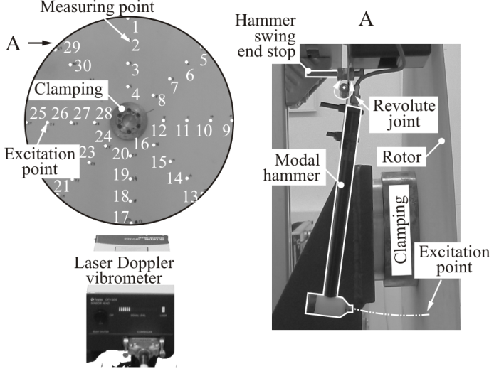 | Figure 4. The configuration of experimental set-up for the determination of modal parameters with marked measuring and excitation points |
4.2. Results
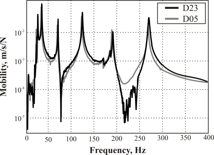 | Figure 5. Example of FRFs obtained for discs without and with delamination of 3% located on ply (n-1) for measuring point 1 (cp. Fig. 4) |
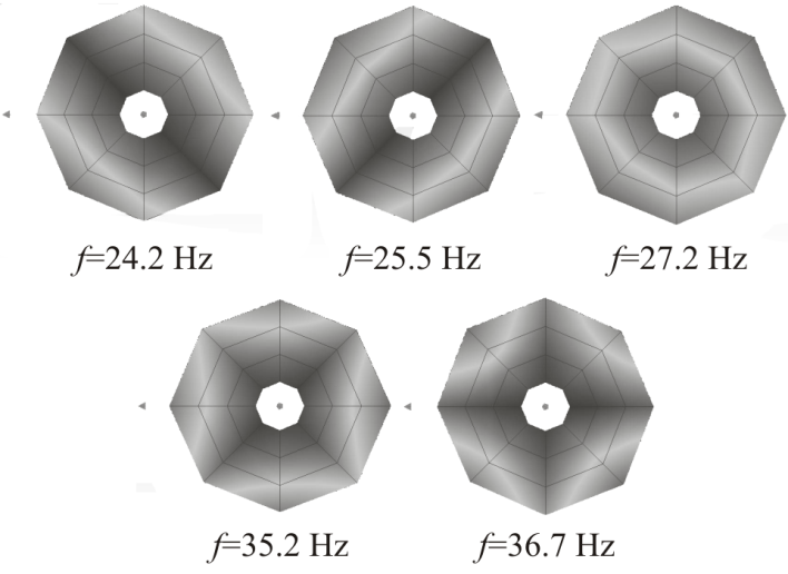 | Figure 6. Eigenmodes of the D17 healthy rotor. The eigenfrequencies are the mean values of all healthy rotors |
4.3. Sensitivity Analysis of Modal Parameters to Manufacturing Scatter and Delaminations
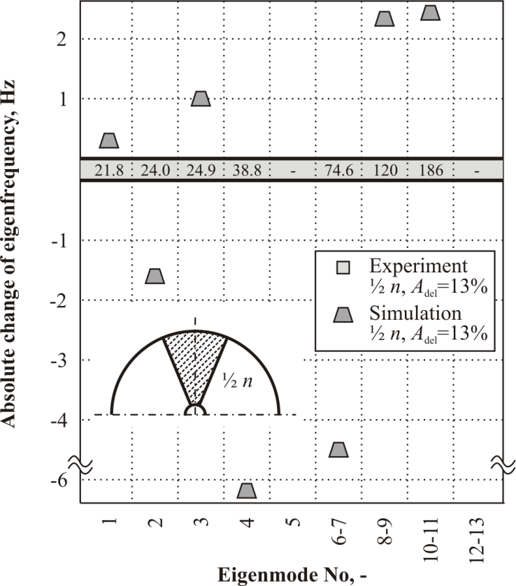
- In the sensitivity analysis, firstly modal parameters scatter due to manufacturing tolerances and repeatability of measurement system were estimated for the healthy rotors. The scatter of eigenfrequencies between three undamaged rotors was calculated. The minimal, maximal as well as the mean value of eigenfrequency are presented in Fig. 7 in black colour bars. The change of eigenfrequency due to introduced delamination is presented with gray markers on the same figure.
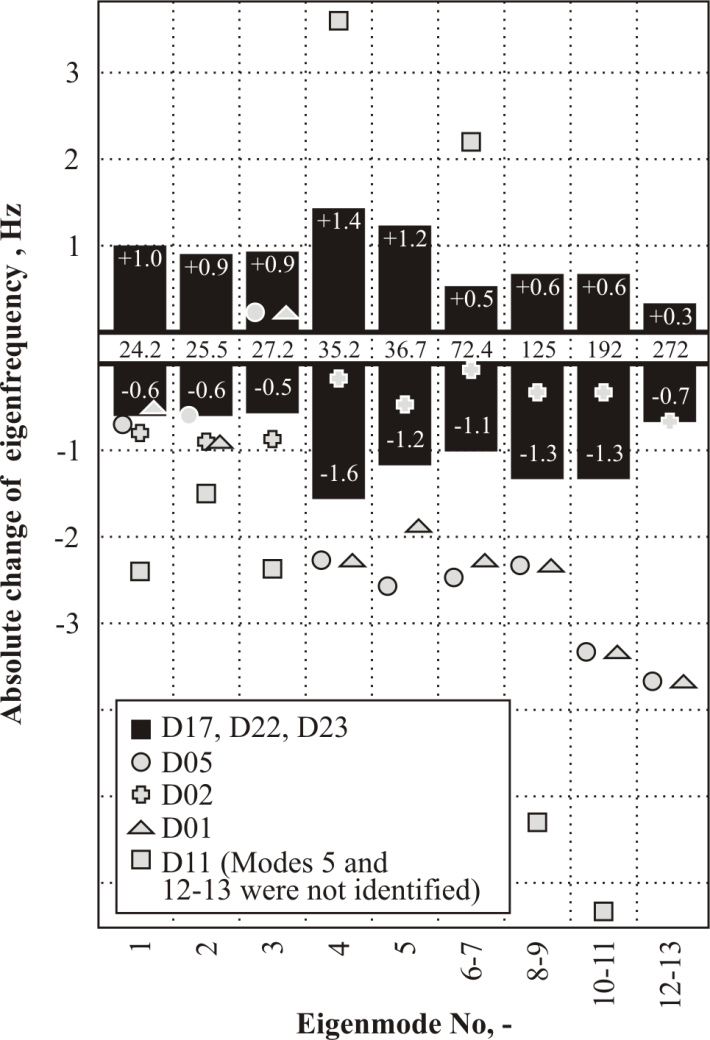 | Figure 7. Sensitivity of particular eigenmodes to induced delamination |
5. Numerical Modal Analysis
- Since the amount of available experimental data was not sufficiently large for the formulation of generalised relations, an FE model was developed and calibrated using the experimentally obtained modal parameters. The numerical modal analysis was then performed in order to generate data for different cases of delamination and to formulate extended qualitative relations between delamination characteristics and modal parameters.
5.1. Parametrised FE Model of the Disc Rotor
- The disc rotor was modelled with the use of commercially available finite element software[16]. Element SOLSH190 was used to model behaviour of an individual layer of the composite rotor and element CONTAC52 was used to model the delamination. The principle of connecting finite element SOLSH190 with CONTAC52 is presented in Fig. 8. The application of CONTAC52 allows the modelling the behaviour of delaminated layers by preventing their penetration. The remaining degrees of freedom in the delaminated region are allowed.
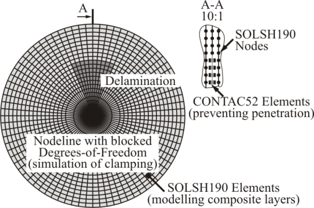 | Figure 8. General overview on the developed parametrised FE model |
|
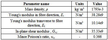
5.2. Model Calibration
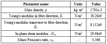
- An important prerequisite for the successful application of the created FE model lies in its proper calibration. Here, the experimentally obtained material parameters were varied within a narrow range in order to match the simulated modal parameters with those obtained in the experiments. Such procedure is inevitability required to include effects of unknown magnitude like limited stiffness of the clamping, manufacturing scatter, and problematic measurement of shear modulus.A comparison of eigenfrequencies simulated using calibrated FE model and those obtained experimentally is presented in Fig. 9. A summary of the optimised model parameters is presented in the Tab. 4.
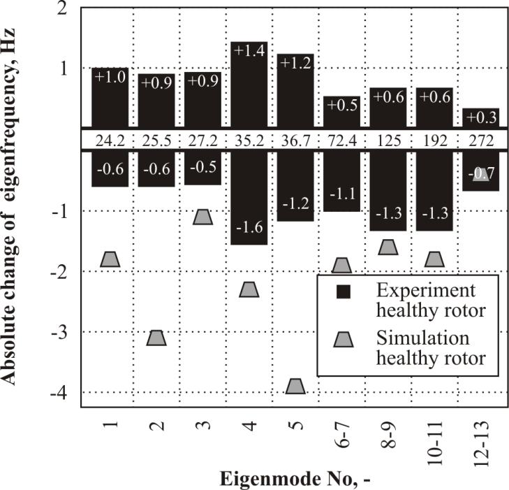 | Figure 9. Goodness-off-Fit of modal parameter simulation after FE model calibration for undamaged rotor |
|
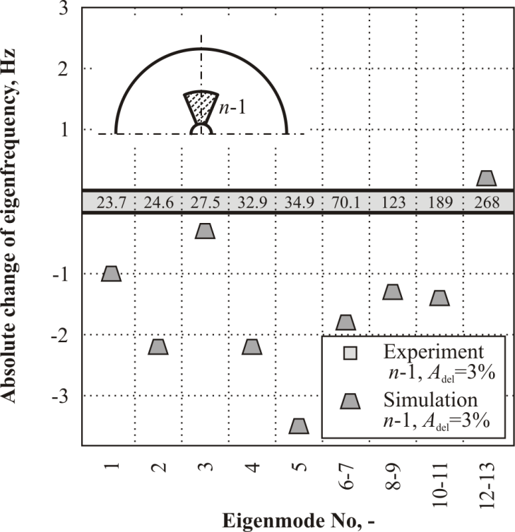 | Figure 10. Goodness-of-Fit for the 3% delaminated in n-1 layer rotor |
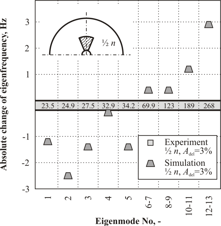 | Figure 11. Goodness-of-Fit for the 3% delaminated in ½ n layer rotor |
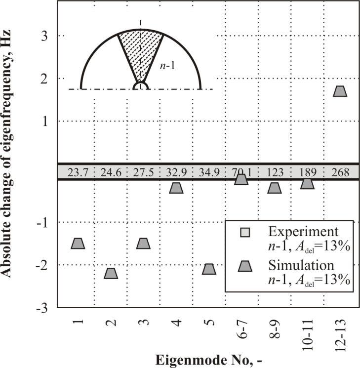 | Figure 12. Goodness-of-Fit for the 13% delaminated in n-1 layer rotor |
 | Figure 13. Goodness-of-Fit for the 3% delaminated in ½ n layer rotor |
5.3. Simulation Results and Discussion
- The numerical modal analysis was carried out using the calibrated parametrised FE model in order to comprehensively investigate the influence of the through-thickness delamination position on the eigenfrequencies.This position was varied from n-1 to ½ n (assumed symetrical from top to middle ply and from bottom to middle ply). The relative size was assumed constant Adel=3%, the inner and outer delamination radius was equal r1=R1 and r2=½ R2. Results of these investigations are presented below.
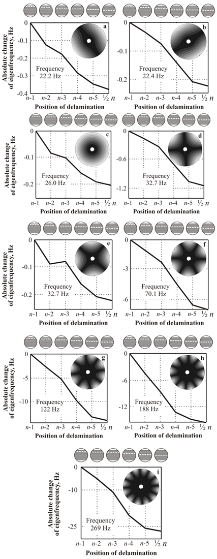 | Figure 14. Absolute change of the eigenfrequency due to through-thickness position variation of the eigenmodes (undamaged rotors as the reference). (a) to (f) Eigenmodes 1 to 6. (g) Eigenmode 8. (h) Eigenmode 10. (i) Eigenmode 12 |
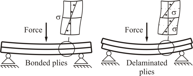 | Figure 15. Influence of delamination on through-thickness distribution of mechanical stress |
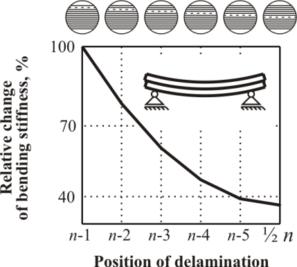 | Figure 16. Absolute change of bending stiffness in relation to through-thickness delamination position (Bonded ply beam as reference) |
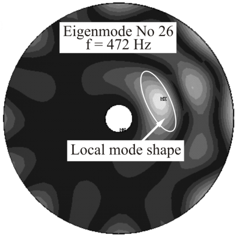 | Figure 17. Local mode shape as a result of delamination |
6. Conclusions
- The effect of delamination’s through-thickness position on the eigenfrequencies of laminated composite disc rotors has been investigated. In experimental studies healthy and delaminated rotors were considered. The results were mainly used to the numerical model calibration and validation although several regularities in the eigenfrequency change due to delamination were found.In the numerical modal analysis, conducted using calibrated FE model, extended investigations regarding the impact of through-thickness delamination position on eigenfrequencies were performed. Obtained results of research indicate that the reduction of eigenfrequency can result from change of bending stiffness of delaminated structure.The future work will deal with the influence of centrifugal forces on the dynamic behaviour of delaminated rotors. An appropriate experimental setup and extended simulation techniques should give an insight into complex, damage dependent patterns of modal properties at different rotational speeds.
ACKNOWLEDGEMENTS
- The authors gratefully acknowledge the financial support of the European Centre for Emerging Materials and Processes Dresden (ECEMP) funded by the European Union and the Free State of Saxony.