Marcelo L. Ribeiro 1, Ricardo Afonso Agélico 2, Ricardo de Medeiros 2, Volnei Tita 2
1Aerospace Engineering, Federal University of Santa Catarina, Joinville Campus, Brazil
2Department of Aeronautical Engineering, São Carlos School of Engineering, University of São Paulo, São Carlos, Brazil
Correspondence to: Volnei Tita , Department of Aeronautical Engineering, São Carlos School of Engineering, University of São Paulo, São Carlos, Brazil.
| Email: |  |
Copyright © 2012 Scientific & Academic Publishing. All Rights Reserved.
Abstract
The prediction of dynamic behavior for composite laminates is very complex, because of many concurrent phenomena can take place during impact load. Fiber breakage, delaminations, matrix cracking, plastic deformations due to contact and large displacements are some effects. Thus, in this work, some mechanisms are simulated by using a new failure model, which considers five failure modes: two for fiber-failure (FF) and three for inter-fiber-failure (IFF). For FF modes, the ply fails under longitudinal tension or compression. For IFF modes, the ply fails under shear stress combined to transverse tension (Mode A) or transverse compression stress (Mode B or C). Each failure mode has a failure criteria and an associated degradation function, which decreases the engineering material properties, requiring an iterative procedure for the process of failure analysis. The material model is implemented as sub-routines written in Fortran (UMAT and VUMAT), which are linked to AbaqusTM. First, the material model parameters were identified based on experimental tests. Second, two parameters were calibrated by using three-point bending tests and implicit numerical simulations with UMAT sub-routine. A computational program in Matlab was developed in order to control the calibration process and the post-processing of the results. After calibration procedure, the material model proposal was applied to predict the response of thin composite disks under impact loads. The finite element analyses via VUMAT were carried out considering the influence not only of the torque value on the screws of the composite disk fixation device, but also the friction coefficient between the composite disk and the fixation device. Finally, the finite element results were compared to experimental data and it was discussed the advantages and limitation of the material model proposal.
Keywords:
Composite Laminates, Material Model, Low Velocity Impact, Finite Element Analysis
Cite this paper: Marcelo L. Ribeiro , Ricardo Afonso Agélico , Ricardo de Medeiros , Volnei Tita , Finite Element Analyses of Low Velocity Impact on Thin Composite Disks, International Journal of Composite Materials, Vol. 3 No. 6B, 2013, pp. 59-70. doi: 10.5923/s.cmaterials.201310.07.
1. Introduction
During the last years, criteria of aircraft projects have been more and more rigorous for structural components, which are developed to absorb impact energy. Numerical and experimental investigations about the development of structural components with high crashworthiness have been carried out by the aeronautical industries. In fact, the project concept for structural components with high crashworthiness depends on the crash resistance concept described by Kindervater and Georgi[1]. The crash resistance concept is based on the energy absorption capacity and structural integrity. However, the prediction of dynamic behavior for composite laminates is very complex, because of many concurrent phenomena can take place during impact load. Fiber breakage, delaminations, matrix cracking, plastic deformations due to the contact and large displacements are some effects, which should be considered when a structure made of composite material is impacted by a foreign object. Therefore, it is very common to find many research works about this issue at the literature, for example: Sari et al.[2], Ribeiro et al.[3] and Tita et al.[4]. In this work, each failure mode has a failure criterion and an associated degradation function, which decreases the engineering material properties, requiring an iterative procedure for the process of failure analysis (Progressive Failure Analyses – PFA). Thus, a material model proposal was implemented as Fortran sub-routines (UMAT and VUMAT) linked to finite element package AbaqusTM for implicit and explicit numerical simulations. First, the material model parameters were identified based on experimental tests described at the literature. Second, two parameters were calibrated by using three-point bending tests and implicit numerical simulations with UMAT sub-routine. Therefore, Finite Element (FE) analyses were performed for a set of parameters. A computational program in Matlab was developed in order to control the calibration process and the post-processing of the results. After calibration procedure, the material model proposal was applied to predict the response of thin composite disks under impact loads, using explicit numerical simulations with VUMAT sub-routines. The finite element analyses were carried out, considering the influence not only of the torque value on the screws of the composite disk fixation device, but also the friction coefficient between the composite disk and the fixation device. Finally, the finite element results were compared to experimental data and it was discussed the advantages and limitation of the material model proposal.
2. Material Model
The material model proposal in this work is a new combination of different failure criteria and degradation laws developed by other researchers. This approach combines the advantages of different models. For example, Hashin’s theory[5] has a good performance to identify fiber failure. On the other hand, Puck and Schürmann’s model[6-7] perform good predictions for inter fiber failure. Furthermore, the Matzenmiller’s degradation law[8] is a good strategy for fiber direction. Moreover, there is a new method for calibration of material model parameters.
2.1. Mathematical Formulation
The material model proposal considers five failure modes for the composite material, which can be divided in two major groups: Fiber Failure (FF) and Inter-Fiber Failure (IFF). The material model criteria for fiber failure (FF) are based on Hashin’s Theory[5]. The material model criteria for inter-fiber failure (IFF) are based on Puck’s Theory[6-7]. Fiber failure criteria are evaluated for tensile loads (FF-T) and for compressive loads (FF-C) in direction 1. Inter-fiber failure criteria are evaluated for three failure modes: Mode-A (IFF-A), Mode-B (IFF-B) and Mode-C (IFF-C). It is important to highlight that the Puck’s work nomenclature is used in this paper, i.e. || is related to the direction of the fibers and ┴ is associated to the transverse direction of the fibers. The IFF modes consider that the failure occurs in the plane 2-3 as shown by Figure 1. IFF-A mode is caused by shear and transverse tensile stress. IFF-B and IFF-C modes are produced by shear and transverse compressive stress.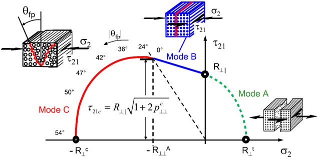 | Figure 1. Failure surfaces for IFF Mode |
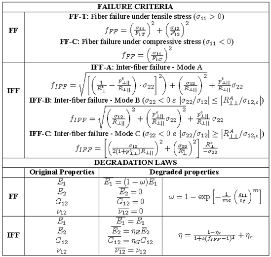
Table 1 can summarize the equations and parameters associated to the material model proposal. The actuating plane stress state determined by the constitutive equations is verified by using the failure criteria and the allowable stresses. Each failure criterion gives a value, and if this value is greater than the unit, then it indicates the material failure. Thus, once it is verified the failure in a material point, i.e. the failure index fFF > 1 or fIFF > 1, the material properties of this region of the continuum needs to be reduced as a consequence of the failure mode. Thus, associated to each failure mode, there are degradation laws where mechanical properties are decreased based on experimental observations. For FF failure modes, the longitudinal Young’s Modulus (E1) is reduced according to the parameter ω, considering the Matzenmiller’s Theory[8], and the transverse properties (E2, ν12 and G12) are assumed to be zero (Table 1). If the ply fails under IFF modes, then the longitudinal properties are not changed, but the E2 and G12 are decreased according to the parameter η established by the Puck and Schürmann’s work[6-7] (Table 1). As it is observed, the material properties are reduced when FF or IFF take place. Then, considering a Progressive Failure Analyses, this reduction can influence the FF or the IFF process in the next step. Thus, it is possible to mention that there is certain interaction between fiber failure and inter-fiber failure.Table 1. Summary of the material model proposal: failure criteria and degradation laws
 |
| |
|
Figure 2 shows the parameters variation (e and m) for composite specimens made of unidirectional (UD) prepreg M10[4, 9], using the degradation law of FF mode.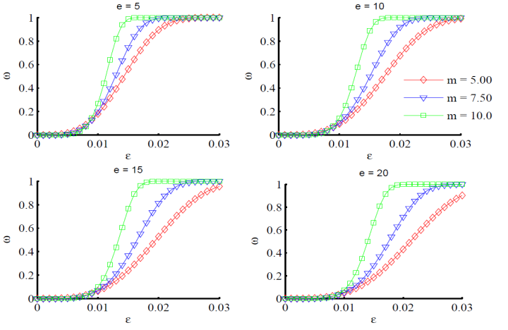 | Figure 2. Parameters variation e and m in function of strain: composite specimens made of UD prepreg M10 |
As observed in the Figure 2, it was necessary to use experimental data to identify the parameters e and m. After some calculi based on the experimental results for[0]10 uniaxial tensile tests of UD prepreg M10, the parameters e equal 9.5 and m equal 3.8 showed a good correlation between the fit curve and the experimental results[4, 9] as shown by Figure 3(a). Due to the difficult to obtain the complete experimental test curves for compression loadings, the material model parameters were identified using the value of ultimate compression stress, which is equal 930 MPa[4, 9]. Thus, the parameters value of e equal 16.0 and m equal 4.7 have shown to perform the best fit for the compression part of the curve as shown by Figure 3(a).Figure 3(b) shows the degradation variables related to IFF modes. The parameters ηE and ηG depend on the failure index fIFF. Since the UD prepreg M10 consist on a composite made of epoxy resin reinforced by unidirectional carbon fiber, it was used the same values obtained by Puck and Sührmann for carbon-epoxy composite specimens[7].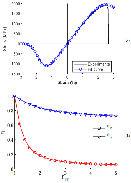 | Figure 3. Degradation parameters: (a) fit curves (FF mode); (b) parameters η (IFF modes)[7] |
2.2. Computational Implementation and Parameters Calibration
The material model proposal was implemented as a Fortran subroutine for implicit finite element code, using UMAT (User Material Subroutine), which was linked to software AbaqusTM. Figure 4 shows the method used during the parameters calibration process, where a program in MatLab was developed in order to carry out automatically this procedure.As flexural loadings are very important during low velocity impact on composite structures, two material model parameters were calibrated, considering these loadings, before to be used in the explicit finite element analyses. Finally, after a complete degradation the respective elements are retained with almost zero stiffness to avoid numerical issues.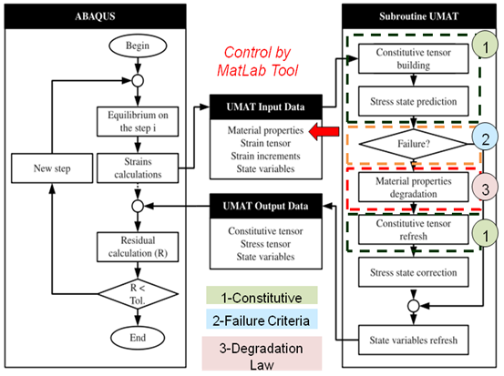 | Figure 4. Methodology used for parameters calibration |
3. Finite Element Models
Two groups of Finite Element (FE) models were developed in this work. The first group simulates three-point bending tests of[0]10 and[0/90/0/90/0]s laminates, i.e. implicit finite element analyses. This group was used not only to evaluate the material model proposal (implemented via UMAT), but also to calibrate material model parameters m and e related to the degradation of material properties due to fiber failure mode (FF). The second FE models group simulates impact test on a composite disk, i.e. explicit finite element analyses. This group was used to evaluate the limitation and advantages of the material model proposal (implemented via VUMAT), considering the influence not only of the torque value on the screws of the composite disk fixation device, but also the friction coefficient between the composite disk and the fixation device.
3.1. Three Point Bending Finite Element Model
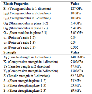
These FE models consist on a flat composite plate (made of UD prepreg M10) to simulate 3-point bending test. Table 2 shows the material elastic properties and the strength values used in the implicit numerical simulations.The flat plate had 80 mm of length, 25 mm of width and span of 58 mm between supports (Figure 5). The supports had diameter of 8 mm and were considered rigid. For boundary conditions, all the degrees of freedom of the two external rigid surfaces were restricted at the reference points (Figure 5). A prescribed displacement of 8 mm in z direction was applied at the reference point of the middle rigid surface (Figure 5). Hard contact law implemented at AbaqusTM was used to simulate the normal interactions between the laminate shell and rigid surfaces of the 3-point bending device. The step size for initial increment was equal 1% for maximum increment and, equal 3% of the total prescribed displacement.Table 2. Elastic properties and strength values[4,9]
 |
| |
|
The finite element mesh is generated by shell elements with full integration (S4) and three integration points through the thickness for each layer. Figure 5 shows the finite element model, where the equilibrium is considered on deformed configuration. Also, the finite element analyses are performed by the control of the displacement of the load applicator at the middle-span. Two stacking sequences were evaluated in order to calibrate the material model parameters. Laminate 1 had 1.73 mm of total thickness and stacking sequence equal[0]10. Laminate 2 had 1.77 mm of total thickness and stacking sequence equal[0/90/0/90/0]s.
3.2. Impact Finite Element Model
These FE models consist on a flat composite plate (made of UD prepreg M10) under low velocity impact. Table 2 shows the material elastic properties and the strength values used in the explicit numerical simulations. In addition, it was used the parameters calibrated by the three point bending analyses. It is important to highlight that the impact analyses follow guidelines provided by standard ASTM D5628-9[11]. The composite specimen was simulated by using shell elements with full integration (S4) and three integration points through the thickness for each layer (Figure 6). Also, it was modelled the whole coupon fixture in order to have more realistic boundary conditions (Figure 6). For the steel fixture discs, it was used 8 nodes linear hexahedron elements with full integration (C3D8). All the displacements degrees of freedom of the lower metal disc were restricted. The screws of the device were simulated by using 8 nodes linear brick elements with reduced integration (C3D8R). Thus, in order to investigate the influence of the torque on the screw, a small Uz displacement was applied to simulate the screw compression forces on the fixture steel disks. For 27 Nm and 50 Nm of torque, the Uz displacement is equal -0.157 mm and -0.291 mm, respectively. The normal interaction between the composite plate and fixtures was simulated using a hard contact law. A penalty contact algorithm with a specific friction coefficient was applied to simulate the tangential interaction. Thus, in order to simulate the influence of this parameter, two reasonable values (0.1 and 0.3) were selected to simulate the friction between composite plate and steel fixture disks. The same interaction properties were applied to simulate the contact between the impactor and composite plate. The mass of 1.2 Kg, which corresponds to the total of impact mass, was simulated applying this value at the impactor reference point. At this point, an initial velocity of 3.130 m/s is also imposed. The impactor was modelled by 4 nodes rigid bilinear quadrilateral element (R3D4).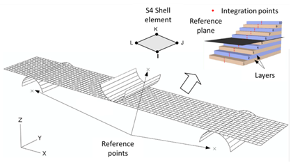 | Figure 5. Three point bending FE model: mesh, boundary conditions and element integration points |
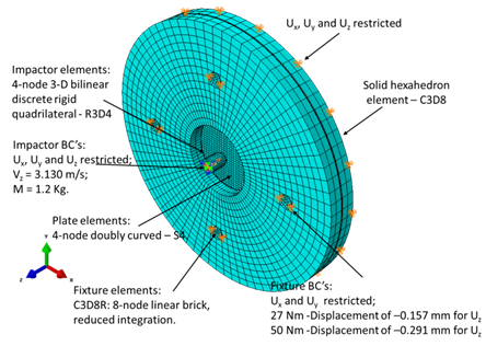 | Figure 6. Impact test FE model: mesh, boundary conditions and initial conditions |
4. Results
4.1. Results for Three Point Bending Analyses
Figure 7(a) shows the FE results for[0]10 (Laminate 1) and Figure 7(b), for[0/90/0/90/0]s (Laminate 2). The shaded areas correspond to the experimental test envelop. Also, it is shown the numerical results provided by another material model[4].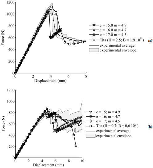 | Figure 7. Parameters calibration: (a) unidirectional 0o-[0]10; (b) cross-ply laminate –[0/90/0/90/0]s. |
 | Figure 8. Three point bending tests and numerical simulations: (a)[0]10; (b)[0/90/0/90/0]s. |
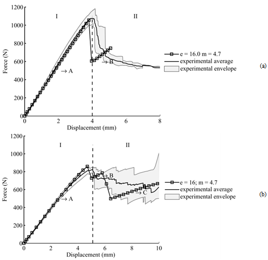
After some implicit simulations, it is possible to select more adequate values for the parameters via calibration process via the program in MatLab. For instance, Figure 8 shows a comparison between experimental and FE results provided by the material model proposal, considering e equal 16.0 and m equal 4.7. It is important to highlight that these values were used in the impact numerical analyses. As commented earlier, this strategy was applied, because the low impact velocity tests are driven by flexural loadings. Thus, this is one of the reasons that three-point bending tests were selected to calibrate the parameters of the material model proposal. There are other reasons for using three point bending tests, such as, it is a simple test to be carried out and it is not so complicated to manufacture the composite specimens.
4.2. Results for Impact Analyses
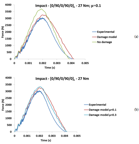 | Figure 9. [0/90/0/90/0]s force vs. time impact results for 27 Nm of torque: (a) Experimental, undamaged and damage simulations results; ( b) Friction coefficient influence on numerical analyses |
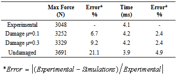
Figure 9(a) shows force-time graphics for thin composite disk with stacking sequence[0/90/0/90/0]s, under 5.91 J impact energy and 27 Nm of torque on screws of the fixture device. In the experimental data, there is a region with oscillations of high frequency (from 0 until 1.2 ms). From 1.8 ms, there are some small oscillations, which show damage process. Due to the stacking sequence[0/90/0/90/0]s (cross-ply laminate), the main failure mechanisms are the matrix rupture and delaminations, which reduces the global stiffness of the structure. Therefore, there is not abrupt drop of the impact force value after the progressive damage process initiation. The FE analyses via AbaqusTM using the material model proposal (implemented via VUMAT) were able to simulate the initial oscillations of the impact (from 0 until 0.5 ms). By the other side, the numerical simulations via AbaqusTM with no damage were also capable to simulate those initial oscillations. However, the maximum peak force is closer to the experimental maximum value when is used the material model proposal. The duration of the impact event is around 4.1 ms for the experimental test, 4.2 ms for the damaged model and 3.9 ms for the undamaged model (Figure 9(a)).The influence of friction coefficient was also studied. The results for friction coefficient (μ) 0.1 and 0.3 are shown in Figure 9(b). It is observed that the higher friction coefficient increases a little the maximum force peak. This increasing is due to the tangential interaction forces between the fixture and composite plate, where higher friction coefficient produces higher tangential reaction forces. Table 3 shows results for the composite disk with stacking sequence[0/90/0/90/0]s and 27 Nm of torque on screws, as well as comparisons between experimental and FE results.Table 3. Results for torque of 27 Nm -[0/90/0/90/0]s
 |
| |
|
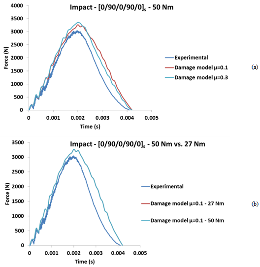 | Figure 10. [0/90/0/90/0]s force vs. time impact results for 27 Nm of torque: (a) Experimental, undamaged and damage simulations results; (b) Friction coefficient influence on numerical analyses |
Figure 10(a) shows the results for thin composite disk with stacking sequence[0/90/0/90/0]s, regarding the different friction coefficients and 50 Nm of torque on screws. As for the previous case, for lower friction coefficient, the model had the force peak decreased a little bit. Figure 10(b) shows that there are not any difference between the results for 27 Nm and 50 Nm of torque. Thus, for the next FE analyses, it is assumed that the torque value is equal 27 Nm, but different values for the friction coefficient are still considered (0.1 and 0.3).Figure 11(a) shows force-time graphics for composite disk with stacking sequence[0]10 under 5.91 J impact energy. The experimental data shows high frequency oscillations in the beginning of the impact event, as well as some lower frequency oscillations (from 0 ms until 0.5 ms), which was not simulated by the FE models.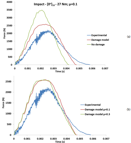 | Figure 11. [0]10 force vs. time impact results for 27 Nm of torque: (a) Experimental, undamaged and damage simulations results; (b) Friction coefficient influence on numerical analyses |
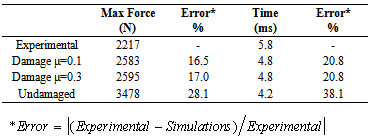
Table 4. Results for torque of 27 Nm -[0]10
 |
| |
|
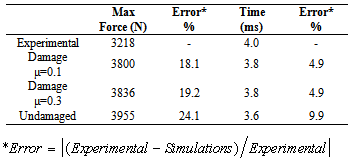
Despite the others lay-up shown in this work, the 0º lay-up shows an abrupt drop on the force around 1.8 ms. For this laminate, failure mechanisms are more severe than for the previous cases. For example, fiber breakage absorbs much more energy than matrix damage[10]; so the force peak is lower and the impact duration is bigger for this laminate. The friction coefficient had a little effect on the numerical results for[0]10 laminates as shown by Figure 11(b). The model with 0.3 friction coefficient resulted in a maximum reaction force, i.e. only 12 N greater than the model with 0.1 friction coefficient (less than 0.5% of the maximum force). Table 4 shows results for the composite disk with stacking sequence[0]s and 27 Nm of torque on screws, as well as comparisons between experimental and FE results. For this laminate, the deviations of FE results from the experimental result are greater than for the cross-ply laminates[0/90/0/90/0]s regardless the friction coefficient. However, it is possible to observe that the material model proposal improves the finite element results, mainly the prediction of maximum force.Finally, Figure 12(a) shows force-time graphics for composite disks with stacking sequence[+45/-45/+45/0/90]s under 5.91 J impact energy. The quasi-isotropic laminate behaves rather similar to cross-ply laminates. For the experimental data, there is a region with oscillations of high frequency (from 0 until 1.2 ms). From 1.8 ms, there are some small oscillations, which show damage process. As for the cross-ply laminate, the main failure mechanisms are the matrix rupture and delaminations, which reduce the global stiffness of the structure. Therefore, there is no abrupt drop of the impact force value after the progressive damage process initiation. The FE analyses with the proposed material model were capable to simulate the initial oscillations of the impact (from 0 until 0.2 ms).By the other side, the numerical simulations with undamaged model were also capable to simulate those initial oscillations. For this laminate, the maximum peak force provided by the proposed material model as well as estimated by the model with no damage are not so close to the experimental maximum value. The duration of the impact event is around 4.0 ms for the experimental, 3.8 ms for the damage model and 3.8 ms for the undamaged model (Figure 12(a)).For this lay-up as for[0]10 laminate, the friction coefficient used to model the tangential behavior by the contact algorithm did not affect the impact response (Figure 12 (b)). The difference due to friction coefficient is only 36N, i.e. less than 1% of the maximum simulation force.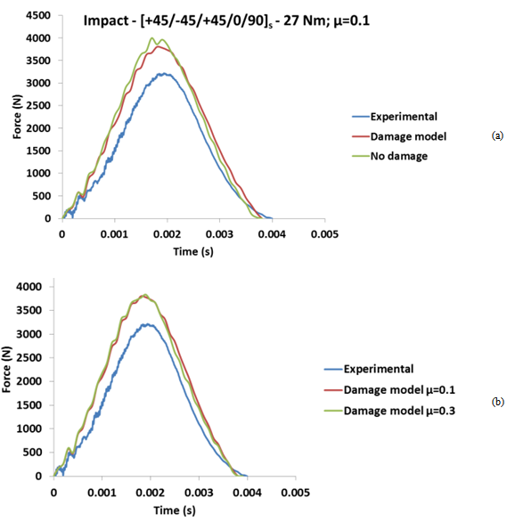 | Figure 12. [+45/-45/0/90]s force vs. time impact results for 27 Nm of torque: (a) Experimental, undamaged and damage simulations results; (b) Friction coefficient influence on numerical analyses |
Table 5 shows results for the composite disk with stacking sequence[+45/-45/0/90]s and 27 Nm of torque on screws, as well as comparisons between experimental and FE results.Table 5. Results for torque of 27 Nm -[+45/-45/0/90]s
 |
| |
|
5. Conclusions
The material model proposal is a new failure model because consists on a combination of different failure criteria and damage evolution law. The parameters associated to the degradation of the material properties due to fiber failure were deeply investigated. It can be concluded that the investigation of these parameters is fundamental to understand how it affects the structural behavior, as well as the relevance of one parameter in relation to the others. Also, it can be concluded that the calibration process of the parameters related to the composite material model needs to be consider for different stacking sequences. Regardless the difficulties related to three point bending tests (matrix crushing under the load applier), the material model performed good numerical predictions for this quasi-static case. However, the simulation for an impact event represents a bigger challenge. As it can be observed, the proposed material model could predict very well the behavior of cross-ply laminates, determining with accuracy the maximum force peak and the impact duration. On the other hand, the model performance for the others lay-up was not so good with error higher than 16% for force peak. This can be partially explained through the calibration process, which is better performed for cross-ply laminate. Another reason for the poor model accuracy is due to lack of delamination criteria. The simulation of this phenomenon is essential for laminates, which presents mainly delaminations during impact events.A parametric investigation regarding the applied torque on the fixture screws has shown that the influence on the results was low for the applied values. Other parametric study presented the effect of tangential friction coefficient used on the AbaqusTM contact algorithm. Based on the FE results, it is possible to conclude that the friction coefficient has a small influence on the numerical simulations, considering the investigated values.
ACKNOWLEDGEMENTS
The authors are grateful for the support from CTM (Navy Technological Center – Brazil), São Paulo Research Foundation (FAPESP process number: 2009/00544-5), National Council of Research (CNPq process number: 208137/2012-2), AFOSR and US-Army (Grant/Contract Number: FA9550-10-1-0011). The authors also would like to thank Prof. Reginaldo Teixeira Coelho (São Carlos School of Engineering – University of São Paulo) for providing the AbaqusTM license.
References
| [1] | C. M. Kindervater and H. Georgi, "Composite strength and energy absorption as an aspect of structural crash resistance," Structural crashworthiness and failure, pp. 189-235, 1993. |
| [2] | M. Sari, R. Karakuzu, M. E. Deniz, and B. M. Icten, "Residual failure pressures and fatigue life of filament-wound composite pipes subjected to lateral impact," Journal of Composite Materials, vol. 46, no. 15, pp. 1787-1794, 2012. |
| [3] | M. L. Ribeiro, V. Tita, and D. Vandepitte, "A new damage model for composite laminates," Composite Structures, vol. 94, no. 2, pp. 635-642, 2012. |
| [4] | V. Tita, J. Carvalho, and D. Vandepitte, "Failure analysis of low velocity impact on thin composite laminates: Experimental and numerical approaches," Composite Structures, vol. 83, no. 4, pp. 413-428, 2008. |
| [5] | Z. Hashin, "Failure Criteria for Unidirectional Fiber Composites," Journal of Applied Mechanics, vol. 47, no. 2, pp. 329-334, 1980. |
| [6] | A. Puck and H. Schürmann, "Failure analysis of FRP laminates by means of physically based phenomenological models," Composites Science and Technology, vol. 58, no. 7, pp. 1045-1067, 1998. |
| [7] | A. Puck and H. Schürmann, "Failure analysis of FRP laminates by means of physically based phenomenological models," Composites Science and Technology, vol. 62, no. 12-13, pp. 1633-1662, 2002. |
| [8] | A. Matzenmiller, J. Lubliner, and R. L. Taylor, "A constitutive model for anisotropic damage in fiber-composites," Mechanics of Materials, vol. 20, no. 2, pp. 125-152, 1995. |
| [9] | V. Tita, "Contribution to the study of damage and progressive failure analyses of composite structures," PhD Thesis, São Carlos School of Engineering, University of São Paulo, 2003 (in Portuguese). |
| [10] | S. Abrate, "Modeling of impacts on composite structures," Composite Structures, vol. 51, no. 2, pp. 129-138, 2001. |
| [11] | American Society for Testing Materials. D5628-96: standard test method for impact resistance of flat, rigid plastic specimens by means of a falling dart (tup or falling mass). Philadelphia, 1996. |
 Abstract
 Reference
 Full-Text PDF
 Full-text HTML