-
Paper Information
- Next Paper
- Previous Paper
- Paper Submission
-
Journal Information
- About This Journal
- Editorial Board
- Current Issue
- Archive
- Author Guidelines
- Contact Us
International Journal of Composite Materials
p-ISSN: 2166-479X e-ISSN: 2166-4919
2013; 3(6B): 53-58
doi:10.5923/s.cmaterials.201310.06
Structure-integrated Active Damping System: Integral Strain-based Design Strategy for the Optimal Placement of Functional Elements
 Abstract
 Reference
 Full-Text PDF
 Full-text HTML
Pawel Kostka , Klaudiusz Holeczek , Werner Hufenbach
Institute of Lightweight Engineering and Polymer Technology (ILK), Technische Universität Dresden, Dresden, 01307, Germany
Correspondence to: Klaudiusz Holeczek , Institute of Lightweight Engineering and Polymer Technology (ILK), Technische Universität Dresden, Dresden, 01307, Germany.
| Email: |  |
Copyright © 2012 Scientific & Academic Publishing. All Rights Reserved.
In this paper a design strategy is presented for the identification of optimal positions and orientations of composite-integrated actuating/sensing elements for the purposes of an active vibration damping suppression. This publication address mainly the problem of structure’s critical natural vibrations damping that cannot be achieved by conventional passive measures. This approach is based on the mathematical analysis of strain fields on the surface of a vibrating with an eigenmode structure with the goal of identifying regions with the maximal strain integrated over the size of selected actuating/sensing element. The required strain fields of the investigated structure can be obtained either from a simulation using a numerical model or from measurements using, e. g. image sequence analysis or strain gauging technique. The proposed procedure is presented in a step-by-step manner on an example of a complex-shaped fibre reinforced composite structure although it can be applied for other materials allowing element integration.
Keywords: Active Damping System, Function Integration, Smart Structure, Design Strategy
Cite this paper: Pawel Kostka , Klaudiusz Holeczek , Werner Hufenbach , Structure-integrated Active Damping System: Integral Strain-based Design Strategy for the Optimal Placement of Functional Elements, International Journal of Composite Materials, Vol. 3 No. 6B, 2013, pp. 53-58. doi: 10.5923/s.cmaterials.201310.06.
Article Outline
1. Introduction
- Every in-service structure is to a greater or lesser extent exposed to vibrations. These can be either structure born – for example resulting from realised process characteristics – or have external causes like wind, noise etc. The vibrations can, in the worse case, lead to the structure’s catastrophic failure due to e. g. fatigue or dynamic overload. An increase of vibration-caused issues can arise from the application of materials with relatively low damping properties like the high-performance lightweight polymer-based composites.Typically, to moderate the vibrations of composite structures, three types of measures can be utilised: application of high damping matrix and fibres, incorporation of external damping elements, or application of additional active elements which functionally mimic an increase of damping[1, 2]. The application range of the first option – application of damping materials – is constrained by the fact that it is not practically possible to increase the damping with stiffness and strength properties remaining unaffected. Therefore, often an increase in structure’s mass is necessary in order to preserve the primary load bearing capabilities. The second measure – incorporation of external damping elements – can be only used when the structure’s surface is accessible and there are no restrictions regarding good wear resistance or aerodynamics. The last abovementioned possibility of damping increase – application of damping mimicking elements – overcomes all disadvantages of the previously mentioned measures since the vibrations are suppressed by generation of counteracting forces using embedded elements. Such solutions normally consist of material-integrated actuating/sensing elements (ASE), appropriate electric circuits to asses the induced force characteristics, and – if needed – devices for energy transmission. Such solutions are, depending on the configuration of the electric circuit, referred to as active, semi-active or semi-passive damping systems.The main challenge of successful application of such systems lies in the proper identification of position and orientation of necessary material-integrated functional elements since it directly determines the damping system performance. Even though for elementary shaped structures respective positioning strategies have strong closed-form foundations, for complex-shaped structures methods are utilised which require comprehensive datasets of potential solutions. This gap between complexity of the structure and the simplicity of procedure is bridged in the proposed approach.
2. State of the Art
- The progress in miniaturisation of actuator and sensor elements combined with the high maturity of composite manufacturing processes as well as recent advances in the signal analysis have stimulated the development of so-called smart structures[3, 4]. Since the introduction of this modern group of structures, the topic of optimal placement and orientation of actuator and sensor elements was identified as vital for their performance. Hence, a large number of papers dealing with the topics of ASE position optimisation can be found.In general, the strategy for the development of smart structure can be presented as three step decision process[5]:•determination of the functional elements quantity,•optimisation of the ASE placement,•evaluation of the ASE performance.Some authors[6] include in that classification the shape assessment of the ASE, the tuning of the electronic units, and the determination of ASE – host structure bonding layer.One of the main strategies of solving the problematic of ASE placement base on the concept of assessing all locations of an candidate ASE set against some objective function and subsequently iteratively removing those ASE that perform least well until some acceptable value of objective function is reached[5]. Based of that concept, the effective independence (EI) method was introduced in[7]. In the EI approach, the objective function is a contribution of functional elements in maintaining the determinant of the Fischer information matrix. The ASE that contributes the least at each iteration step is deleted from the candidate set. At the end, an optimal set of ASE by means of quantity, position and performance is identified. Similar examples of such iterative approach base on following objective functions: eigenvalue vector product[8], driving-point residue[9], effective independence driving-point residue[10] or modal assurance criterion[11]. This group of approaches is characterised by large computational effort especially since the initial candidate set have to be very extensive in order to include all relevant eigenforms. This disadvantage can be eliminated by a reverse approach where a minimal initial ASE candidate set is extended until the acceptable value of objective function is reach. Nevertheless, an essential characteristic of all this methods is posed by the fact that the analysis of data collected from exhaustive search is very often complex and time-consuming – although the correct result is always obtained.Another group of methods for the ASE position optimisation is constituted on the grounds of artificial intelligence (AI) theory[12-14]. Using that theory, an approximate reasoning about optimal integration position of ASE based on limited amount of information is possible. The main advantage of these methods, in comparison with the aforementioned iterative approaches, lies in the avoiding of the time-consuming exploration. Nevertheless, the final performance of this group of methods is connected with the information-content – and therefore typically with the size – of the utilised dataset of examples.In the proposed strategy for optimal positioning and orientation of ASE, the characteristics of both above presented approaches are combined: the correctness of the iterative methods with the simplicity of AI-based approaches.
3. Integral Strain-based Design Strategy
- The proposed strategy originates from the fact that the vibration suppression using a material-integrated active damping system can be achieved only when the detrimenting vibrations are observable (sensing) and controllable (actuation). Since the typically used ASE induce or acquire mechanical strain, the position of ASE integration need to be associated with the strain distribution in every detrimenting vibration condition.Taking into account the finite, non-zero size of every ASE, its optimal position have to be determined based on structure’s surface strains integrated over the size of the ASE. Additionally, a match of ASE axis of action (cf. Fig. 1) with angle of maximal integral strain on the structure (v. Fig. 5) needs to be assured.
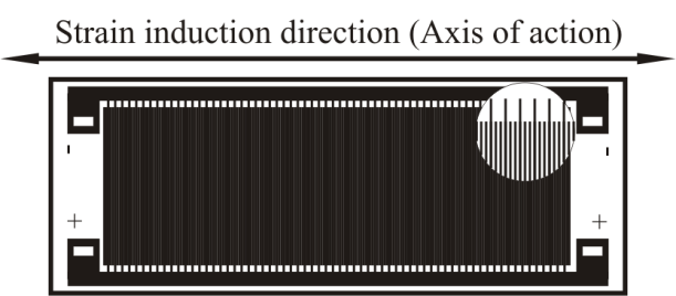 | Figure 1. Example of a low-profile strain sensing/inducing ASE with marked axis of action[17] |
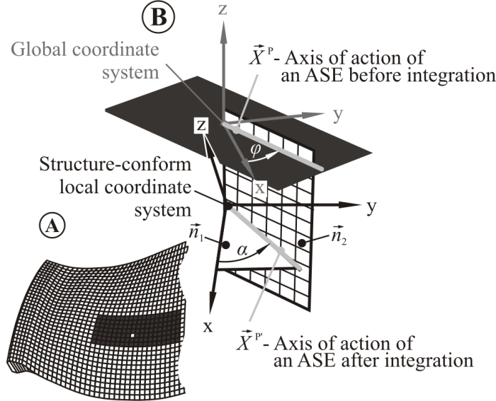 | Figure 2. Transformation of the global strains to local strains. (A) Complex shaped structure with exemplary position of ASE integration. (B) ASE principal axis of action in global and local coordinate system |
 | (1) |
 | (2) |
 | (3) |
 | (4) |
 is the axis of action of an ASE after integration defined as:
 | (5) |
 | (6a) |
 | (6b) |
 | (6c) |
 is the directional vector defining line of intersection of two planes as:
 | (7) |
 and
and  are directional vectors of a plane tangent to the structure’s surface in given point, and a plane normal to the XY-plane of global coordinate system and intersecting that plane in general integration angle φ (cf. Fig. 2).In the next step, the rotated strain tensors for every detrimenting vibration condition are summed over the assumed size of the ASE separately for every general integration angle.
 | (8) |
 | (9) |
4. Case Study: Composite Fan Blade
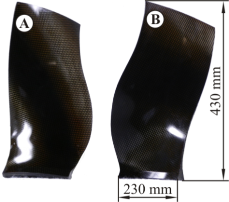 | Figure 3. Structure investigated in case study. (A) Pressure side. (B) Suction side |
4.1. Numerical Model of the Composite Fan Blade
- The simulation with finite-element model of the composite fan blade was performed in order to obtain strain field for the first modeshape. The necessary model was developed using commercial finite element software with application of a 3-dimensional 8-node element based on the Mindlin-Reissner shell theory with enhanced strain formulation[15]. The necessary material properties were obtained from the material database available at the Institute of Lightweight Engineering and Polymer Technology (ILK). Selected degrees-of-freedom in the model were constrained in order to simulate the existing boundary conditions of the investigated structure.The main vibration problem of fan blades is associated with the aeroelastic flutter phenomena. Flutter is a self-driven and potentially destructive vibration condition where aerodynamic forces couple with a structure natural mode. The underlying natural mode is typically the first eigenmode (Fig. 4) of the structure therefore this modeshape was selected as the detrimenting vibration condition in this analysis.
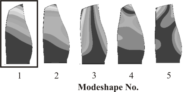 | Figure 4. Eigenforms of the investigated composite fan blade |
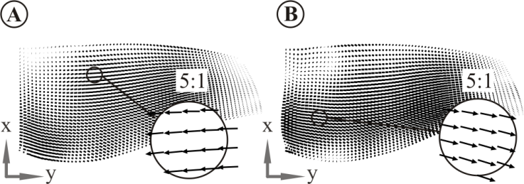 | Figure 5. Distribution of the mechanical strains for the first modeshape presented in structure-conform local coordinate systems. (A) On the blade’s pressure side. (B) On the blade’s suction side |
4.2. Data Transformation
- Firstly, a structure-conform integration angle α was determined according to Eq. 4. The strain field oriented in general integration angle φ equal to zero is presented on Fig. 5. Subsequently, the strains were rotated in order to calculate the strains in actuator's axis of action for every possible global integration angle. An example of strain distribution for two angles – 45° and 90° – are presented on the Fig. 6 for pressure and suction side of the fan blade.Finally, the strains for every combination of angle and position of an assumed ASE are integrated aver the size of the ASE. Initially for this study, a commercially available low-profile ASE with known dimensions was selected. As a characteristic parameter of integration the middle and axis of action of the ASE were selected.
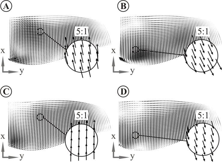 | Figure 6. Distribution of the mechanical strains in local coordinate system after rotation. (A) On the blade’s pressure side rotated by 45°. (B) On the blade’s suction side rotated by 45°. (C) On the blade’s pressure side rotated by 90°. (D) On the blade’s suction side rotated by 90° |
4.3. Determined Position of the ASE
- Out of all candidate positions and orientations of ASE those are selected which are characterised by globally maximal integral strains on the pressure and suction side. In order to compare the potential damping performance a factor was defined as:
 | (10) |
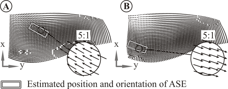 | Figure 7. Estimated optimal positions of ASE. (A) On the pressure side. (B) On the suction side |
4.4. Experimental Validation
- The experimental validation was conducted on two identical composite fan blades – the first one with the ASE applied on the surface and the second one with structure-integrated ASE. The composite fan blades were manufactured in resin-transfer-moulding technology from carbon fibre reinforcement infiltrated with epoxy resin. All quality-relevant fabrication parameters were set according to the specifications of the fabric and resin manufacturers.The investigations were conducted in order to compare the assumption that the difference between the performance of the active damping system with surface applied and integrated ASE optimised using surface input strain is negligible.
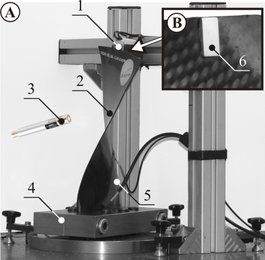 | Figure 8. Experimental set-up. (A).General overview: (1) – Electromagnet for vibration excitation; (2) – Composite fan blade with surface mounted ASE; (3) – Diffuse field microphone; (4) – Clamping; (5) – Surface mounted MFC. (B) Detailed view of surface mounted magnet (6) |
4.5. Results and Discussion
- The measured via ASE timeseries of strain signals for the cases with and without activated damping system for both analysed blades are depicted on the Fig. 9. The results confirm that:● the difference in the performance of the active damping system for surface-applied and integrated ASE is, as assumed, negligible● the vibration suppression performance estimated from the following equation:
 | (11) |
 and
and  are vibration amplitudes of a structure with and without active damping system respectively is high.The
  equals to 96 and 93 for the surface applied and integrated ASE respectively. These values can be interpreted as the percentage reduction of vibration amplitude.
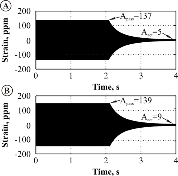 | Figure 9. Strains measured using integrated ASE. (A) Of the composite blade with surface applied ASE. (B) Of the composite blade with integrated ASE |
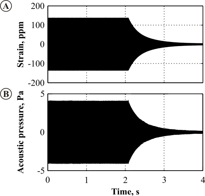 | Figure 10. Acoustic pressure measured with using externally placed microphone on a vibrating blade with surface applied ASE |
5. Summary
- A novel design strategy for the identification of optimal positions and orientations of structure-integrated actuating/sensing elements (ASE) of an active damping system was presented in this paper. Since the ASE are always characterised by a finite, non-zero size, the optimal integration-position was determined based on the strains integrated over the size of the ASE. Additionally, a match of ASE axis of action with angle of structure’s surface integral strain was addressed.The proposed strategy is based on the mathematical analysis of strain fields of a vibrating structure with the goal of identifying regions with the maximal strain integrated over the dimensions of selected actuating/sensing element. This strategy was validated in the case study on example of complex, multi-curved geometry with anisotropic, locally varying material properties, and low intrinsic material damping.The input data for the strategy – strain field occurring while a structure vibrated with first modeshape – was extracted from a numerical simulation. Alternatively, the same data can be acquired from experimental investigations. Since here typically only the surface strains are accessible in the case study two composite fan blades were analysed – with surface applied and integrated ASE. The results confirmed negligible influence of the through-thickness integration position on the overall performance of the active damping system.Summarising, the assumptions of the proposed strategy for optimal, positioning and orientation of arbitrary shaped ASE of an active damping system were proven to be valid.
ACKNOWLEDGEMENTS
- The authors gratefully acknowledge the financial support of the European Union of the research under Grant No. DREAM – FP7-211861 ‘Validation of radical engine architecture systems’ as well as the European Centre for Emerging Materials and Processes Dresden (ECEMP) funded by the European Union and the Free State of Saxony.