-
Paper Information
- Next Paper
- Previous Paper
- Paper Submission
-
Journal Information
- About This Journal
- Editorial Board
- Current Issue
- Archive
- Author Guidelines
- Contact Us
International Journal of Composite Materials
p-ISSN: 2166-479X e-ISSN: 2166-4919
2013; 3(6B): 23-39
doi:10.5923/s.cmaterials.201310.04
Geometrically Non-Linear Analysis of Composite Laminated Plates Subjected to Low-Velocity Impact
 Abstract
 Reference
 Full-Text PDF
 Full-text HTML
Simon Wang 1, Xiuqin Zhang 2, Yingshun Zhang 3, Chenyu Zhang 1
1Department of Aeronautical and Automotive Engineering, Loughborough University, Loughborough LE11 3TU, UK
2Taiyuan University of Technology, 79 West Yingze Street, Taiyuan 030024, Shanxi, China
3Doosan Babcock Energy Limited, Porterfield Road, Renfrew PA4 8DJ, UK
Correspondence to: Simon Wang , Department of Aeronautical and Automotive Engineering, Loughborough University, Loughborough LE11 3TU, UK.
| Email: |  |
Copyright © 2012 Scientific & Academic Publishing. All Rights Reserved.
A B-spline finite strip model is developed in the context of a layer-wise plate theory for analysing the geometrically non-linear transient response of laminated composite plates subjected to transverse low-velocity impact. To simplify the complicated contact analysis, a Hertz-type contact law has been incorporated into the finite strip (FS) model for accounting for the contact behaviour. The model includes the geometrical non-linearity through use of von Karman's non-linear strain-displacement relationship. The resulting non-linear dynamic problem is solved using the Newmark time-stepping scheme together with Newton-Raphson iteration. Several numerical applications are described and a close comparison is found between the results calculated through the present model and the existing analytical and experimental results.
Keywords: Laminated Composite, Low-velocity Impact, Geometrical non-linearity, Transient, B-spline Finite Strip
Cite this paper: Simon Wang , Xiuqin Zhang , Yingshun Zhang , Chenyu Zhang , Geometrically Non-Linear Analysis of Composite Laminated Plates Subjected to Low-Velocity Impact, International Journal of Composite Materials, Vol. 3 No. 6B, 2013, pp. 23-39. doi: 10.5923/s.cmaterials.201310.04.
Article Outline
1. Introduction
- Laminated composite structures have played an important role in aircraft, vehicles and many other demanding applications because of their high strength-to-weight and high stiffness-to-weight ratios. As it is well known, however, these structures are very susceptible to low-velocity impact damage, which can be introduced during manufacture and in service. Impact induced damage can have a significant effect on the strength, stability and reliability of the structures. Therefore, great concern has been received on the low-velocity impact of the structures[1]. For understanding low-velocity impact response of composite structures, several analytical approaches have been used by a number of researchers. These approaches vary from simple mathematical models, such as spring-mass models and energy-balance models, to more complicated dynamic analysis of the impact events.In spring-mass models, the structure is represented by an assemblage of springs and masses. The low-velocity impact event is simulated by a discrete system with a few degrees of freedom. These kinds of model are generally used to estimate the impact force history for the impact events in which the structures behave quasi-statically. Caprino et al[2] used a single degree of freedom model to predict elastic impact response of a small glass cloth-polyester panel due to a drop weight impact. In their model, the panel is represented as a linear spring of stiffness k, which corresponds to the static rigidity of the panel at the impact point. Similar models are also used by others[3,4,5]. Shivakumar et al[6] suggested a two degree of freedom model, in which the impactor and the plate are treated as two masses, and four springs are used to represent the contact stiffness and the bending, shear and membrane rigidities of the plate. Bucinell et al[7] employed the same model to study the response of composite plates to impacts. In the two-degrees of freedom model of Sjoblom et al[8], the plate and contact rigidity is modelled separately using two springs. Toh et al[9,10] also used a two-degrees of freedom model to predict the impact force. Gong and Lam[11] proposed an improved two-degrees of freedom spring-mass model by implementing the structural damping to determine the contact force between the target and striker during impact. Another kind of frequently used simple models for the impact events in which the structures behave quasi-statically are energy-balance models[6,12]. In these models, it is assumed that the velocity of the impactor becomes zero when the structure reaches its maximum deflection. Energy-balance models allow direct estimate of the maximum contact force, considering the conservation of energy without having to compute the entire time history. Whilst they are useful in understanding the main features of low-velocity impact events, the above-mentioned simple models are inadequate in accounting for the dynamic nature of the composite structures under the low-velocity impact. For understanding the initiation and propagation of the low-velocity impact damage as well as the interaction between the damage and plate dynamic response, dynamic analysis is often needed for accurate prediction of low-velocity impact behaviour of the composite laminates. In addition, it is the case that for many situations the responses of the structures in low-velocity impact events cannot be viewed as quasi-static ones. Therefore, it is very important to have an insight into dynamic response of the impacted structures. Dynamic analysis of low-velocity impact response of laminated composites generally involves the global dynamic response of the laminates and the local contact between the impactor and the structure. To model the contact, one of the possibilities is based on a formulation of the joint contact problem for the system of impactor-target. This is tightly connected with the particular numerical method to be applied, for instance, finite element method (FEM), finite difference method, or other method based on some variational principles. In FEM analysis of the impact contact problem, contact elements are used to model the laminate and the impactor [13,14,15,16,17,18,19]. The solution of the contact problem may be achieved using several contact algorithms such as the Lagrange multiplier method[13] and the penalty method[19]. The Lagrange multiplier method has the advantage of enforcing the exact constraints, but induces additional parameters which substantially enlarge the overall size of the equations to be solved. The penalty method is relatively simple and does not require additional equations. With contact algorithms, the contact state is detected at each time step and the contact constraints are imposed to the contacting nodes/elements once contact occurs. Since contact is a non-linear problem, full analysis of the impact contact for the system of impactor-target is a complex and time-consuming procedure. Hence, simplification of the contact problem is often made through use of the contact laws in impact analysis of composite laminates. Yang and Sun[20] have proposed a contact law for contact between a sphere and a composite laminate based on static indentation tests. This contact law accounts for permanent indentation after unloading cycles and uses different relationships between the contact force and the indentation for loading, unloading and reloading processes. Tan and Sun[21] further studied the unloading and reloading process and proposed a modified version of the contact law. Experimental observations[22,23] confirm that loading rate effects during low-velocity impact of composites are insignificant. This suggests that statically determined contact laws may be used for impact analysis of composite structures. The above-mentioned contact laws developed by Sun and his co-workers have gained extensive use in analysing the dynamic response of composite laminates to impact. It should be noted that these contact laws do not give the contact stress distribution under the indentor. Determination of the contact stress distribution has to appeal to analytical method. In addition, these contact laws have not accounted for damage effect on force-indentation relationship. Wu and Shyu[24] showed that the contact phenomenon is different in small and large indentation stages due to occurrence of laminate damage. In the small indentation stage where the plate is intact, the change of laminate stacking sequence has an insignificant effect on the force-indentation relationship. Beyond the small indentation stage, damage occurs and the indentation spring is stiffened as a result of matrix crack and delamination damage of the laminates. The contact behaviour during low-velocity impact is very similar to that in a static test.Because of the complexity of the impact problem, closed-form exact solutions exist only for simple cases. In most situations, approximate analytical and/or numerical methods have to be adopted. In conjunction with contact laws, dynamic analyses of low-velocity impact of composite laminates have been carried out analytically by a number of researchers. Sun and Chattopadhyay[25] studied a simply-supported orthotropic plate subjected to central impact using the first order shear deformable plate theory (FSDPT) developed by Whitney and Pagano[26]. Dobyns[27] used the same method but replaced the concentrated impact load by a uniform patch pressure to avoid transverse shear force singularity at the contact point. Qian and Swanson[28] examined two solution techniques which were based on series expansion. One of them was based on a Rayleigh-Ritz approach with numerical integration in time, and the other was an analytical approach using Laplace transformation of the governing differential equations, but requiring a linearisation of the contact law. Carvalho and Soares[29] studied a simply-supported composite plate subjected to an impact load utilising the technique of Fourier series expansion for the solution of the dynamic plate equations. Comparison was made between the numerical solution technique based on Newmark integration method and the analytical formulation using the Laplace transform technique. Pierson and Vaziri[30] presented a Fourier series solution that retains the frequencies associated with rotary inertia effects. A double Fourier series expansion and the Timoshenko small-increment method were used by Ambur et al[31,32] for determining the transient response of simply supported, rectangular laminated plates subjected to impact loads. Heitzer[33] studied the interaction of an impactor and a clamped, anisotropic plate at low-velocities by assuming a series expansion for the plate deflection. Large deflection was taken into account and the contact law was used.It is well known that FEM is one of the most powerful tools of solution in structural analysis. Besides 2D or 3D finite element analyses of the joint impactor-target system[13-19,34-36], many researchers have employed the FEM in conjunction with contact laws for the analyses of composite laminates due to low-velocity impact. Sun and his collaborators[21,37,38] used static indentation laws and FEM based on FSDPT to analyse the impact responses of composite laminates. The initially stressed composite laminates were studied in[37] and dynamic large deflection was considered in[38]. Wu and Chang[39] developed a 3D finite element code for transient dynamic analysis of laminated composite plates due to transverse foreign object impact in which a contact law is incorporated. Combined with failure criteria this 3D finite element code has been used by Wu and Springer[40], Choi and Chang[41], Finn and Springer[42,43], and Scarponi et al[44] for failure analyses of impacted laminates. Choi and Chang[45-47] developed a 2D FEM for studying the impact damage of laminated composite beam resulting from the line-loading impact. Davies and Zhang et al[48-51] investigated impact-induced damage using FEM based on Mindlin’s plate theory combined with a contact law[22]. The FEM based on FSDPT and a Hertzian-type indentation law was employed by Hu et al[36] for analysing the transient response of composite laminates with multiple delaminations subjected to low-velocity impact. It appears that the majority of previous analytical and numerical analyses are limited to small-deflection behaviour. Although such linear analyses are practical and useful for many impact problems of composite structures, it is often the case that the geometric non-linearity (GNL) has very significant effects on the impact response.In this paper, a layer-wise B-spline finite strip model developed in[52] is extended through introduction of time dimension for the GNL transient analysis of laminated composite plates subjected to transverse low-velocity impact of spherical object within the context of a layer-wise plate theory[53]. It is noted that in[54,55] a B-spline FSM has been used for transient analysis of laminated composite plates subjected to dynamic loads based on the first order shear deformable plate theory (FSDPT). In the present study, the geometrical non-linearity is taken into consideration by use of von Karman's non-linear strain-displacement relationship. The dynamic problem is solved using the Newmark time-stepping scheme in the time domain and the solution of the resulting non-linear equations is sought with Newton-Raphson iteration. The impact problem in the small-deflection regime is briefly discussed as well. Several numerical applications are presented. It is noted that material damage and delamination are not dealt with in the current work.
2. Problem Description and Fundamentals
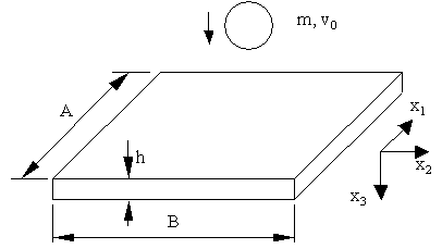 | Figure 1. Transverse impact on a rectangular plate |
2.1. Basic Plate Equations
- In the present study, the layer-wise plate theory proposed by Reddy[53] is adopted for representation of displacement behaviour in the plate. Through the thickness direction, the laminated plate is divided into a desired number, N, of numerical layers, which can be less than, equal to, or greater than the number of physical layers. The assumed displacements (
 ,
, ) at a general point of the laminate, with t as the time dimension, take the form as what follows.
 | (1) |
 and u3 denote the three displacement components of the reference plane (x3=0).
  are piecewise continuous functions and defined as
 | (2) |
 is ranged from 1 to N and
  from 1 to N+1.
  is defined in terms of linear Lagrange interpolation functions
 | (3) |
 is defined as
 | (4) |
 is the number of the layer at which the reference plane is. The resulting displacement configuration is shown in Figure.2.
 | Figure 2. In-plane displacement configuration of layerwise theory |
 | (5) |
 | (6) |
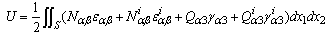 | (7) |
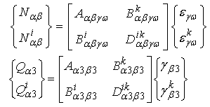 | (8) |
 ,
,  ,
,  , and
, and  are generalised stresses per unit length.
  ,
,  , etc, are the stiffness coefficients of the laminate which are defined as
 | (9) |
 and
and  denote the transformed reduced stiffness coefficients.
  possess symmetry in the indices α and β, γ and ω, and the pairs of αβ and γω. The similar symmetrical property also applies to
  .
.2.2. Finite Strip Approximation
- The whole plate is modelled with a number of finite strips along the crosswise x2-direction. Each strip is further partitioned longitudinally into q sections. A typical individual finite strip element (quadratic strip) is shown in Figure 3. Over the strip each of the fundamental displacement quantities
 ,
, , and
, and  can be approximated as a function of multiplicative type, in which q+k B-spline functions of degree k are used in the longitudinal x1-direction and simple polynomials of degree n in the crosswise x2-direction. Mathematically, the fundamental displacement quantities are given as
 | (10) |
 ,
,  and
and  are column matrices of generalised displacement parameters associated with
  ,
, and
and  , respectively. The row matrices
  and
and  are modified B-spline function bases of order k and k-1 in the longitudinal
  -direction. NI are polynomial functions of degree n in the crosswise
  -direction and here Lagrangian shape functions are used. The superscript i, ranged from 1 to N, is related to the nodes through the thickness. The capital superscript I, ranging from 0 to n, denotes the number of a reference line in the crosswise
  -direction of the strip.
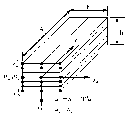 | Figure 3. A typical layerwise finite strip element |
3. Governing Equations of Motion
- In the absence of damping, the governing equations of the plate motion can be given through use of Hamilton's principle in terms of strain energy U, kinetic energy T and potential energy W as
 | (11) |
 | (12a) |
 | (12b) |
 | (12c) |
 | (13) |
 | (14) |
 | (15) |
 | (16) |
 ,
,  and
and  are known at time
  and
and  ,
, ,
, are equal to zero at time
  .
. 4. Problem Solution
- In the time domain the impact problem defined in Eqs.11 and 15 can be solved with a few of different approaches. In the present investigation the solution of the problem is sought using the popular Newmark time integral algorithm. Suppose that the time period concerned is divided into a number of equal time intervals
 and consider the satisfaction of Eqs.11 and 15 at time (n+1)Δt and write
 | (17a) |
 | (17b) |

 ,
, and
and  as
as | (18a) |
 | (18b) |
 and
and  can be chosen as such that good approximation properties to the algorithm are yielded. In this study the constant-average-acceleration version of Newmark method is used, and consequently, β1=β2=1/2. The algorithms yield unconditional stability for linear problems at least. Belytschko and Schoeberle[56] use the Newmark-β method for a nonlinear structural dynamics problem. Their proof of unconditional stability with
  using an energy method applies only to nonlinear material properties but they state that numerical results show unconditional stability with geometric nonlinearity also. Substitution of Eq.18 into Eq.17 leads to a set of non-linear equations in which the unknowns are
  and Fn+1. The non-linear equations can be written in terms of residual forces as
 | (19a) |
 | (19b) |
 | (20a) |
 | (20b) |
 | (21) |
 | (22) |
 is the symmetric tangent stiffness matrix evaluated at iteration i.
  is defined with the condition of
  .
.  and
and  are increments, or iterative corrections, of the unknowns
  and Fn+1 at iteration i, respectively, and they can be given from Eq.20 as
 | (23) |
 and Fn+1. The procedure is repeated until the following convergence criteria are satisfied
 | (24) |
 is used in this work.Up to now the impact dynamic transients are concerned with geometric non-linearity and the solution procedure is described in details as above. For comparison, the impact problem is also investigated within the context of small deflection in this paper. In fact there exists no difference between the geometric non-linear and linear analyses of the impact problem in the temporal approximation. Within a time step, however, the solution procedure used for the linear transient response is different from that described above for the non-linear one, and is here discussed below.In the case of geometric linear analyses of the impact problem, the non-linear strain terms are ignored in the strain-displacement relationship. As a result, the stiffness matrix K becomes independent of the plate displacement. From Eq.19a the following equations can be given
 | (25) |
 | (26) |
 and
and  . These two sets of linear equations can be solved simultaneously since they share the same coefficient matrix. The solution procedures involve triangular decomposition of the coefficient matrix and then forward elimination and back substitution. Most of the computing efforts are expended in the procedure of triangular decomposition of the coefficient matrix during the solution of the equations. Noting the coefficient matrix is independent of time increments, the triangular decomposition of the coefficient matrix is performed ahead of the time iteration in the present methodology and in each time increment only the forward elimination and back substitution are involved. With this strategy, the computer efforts can be greatly reduced. Substitution of Eq.26 into Eq.19b leads to a non-linear equation with respect to Fn+1, and again, the Newton-Raphson iteration technique is adopted for the solution of the non-linear equation. The iterative corrections for Fn+1 can be written as
 | (27) |
 and
and  are the same as those given before and
  are evaluated from Eq.19.
5. Numerical Applications
- The above analysis procedure has been implemented in an in-house computer software. It can be used for impact problems and, neglecting impact-related terms, for plate transient response under dynamic loading. Numerical tests have been conducted to verify the validity of the present computational model, which include a series of examples of composite laminate plates under low-velocity impact. The selected examples of the impact problem refer to two typical kinds of low-velocity impact events, i.e. small impact mass with relatively high speed and large mass with low speed. In all the applications, the quadratic Lagrangian shape functions are applied in the crosswise x2-direction. Unless otherwise specified, the simply supported boundary conditions are defined such that the plate is simply supported for out-of-plane behaviour whilst the in-plane movement of the sides is constrained in the tangent direction but allowed in the normal direction. For the impact problems considered, the contact law defined in Eq.12a is used for both the loading and unloading processes. The details are presented in the following subsections.
5.1. Impact of a[0/90/0/90/0]s Plate
- Consider the impact problem involving central impact of a simply supported square T300/934 graphite/epoxy [0/90/0/90/0]s plate by a steel object with a spherical impact tip of diameter 12.7mm. The plate has dimensions of 200 200 2.69 mm. The material properties of a T300/934 graphite/epoxy lamina are given asE1 = 120 GPa, E2 = 7.9 GPa, ν12 = 0.3G12 =G13 = G23 = 5.5GPa, ρ = 1580 kg/m3Two cases of impact events are considered here, i.e., impact by a 7.5g mass with a velocity of 3m/s and by a 19.6g mass with a velocity of 10m/s, respectively. In the present study, the contact law defined in Eq.12a is simply employed for the whole contact processing. Since the laminate is thin one numerical layer is used with shear correction factor
 and
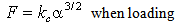
and  , evaluated by the method in Reference[26]Case 1 Impact by a 7.5g mass of 3m/s
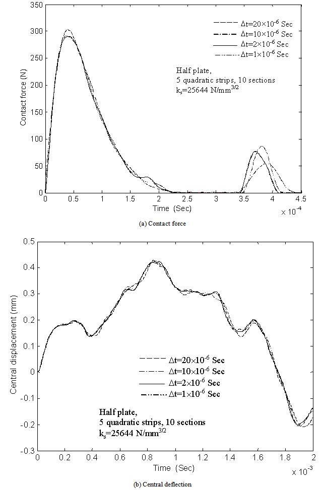 | Figure 4. Convergence with respect to time step for the problem of a[0/90/0/90/0]s plate impacted by a 7.5g mass of 3m/s |
 | Figure 5. Convergence with respect to plate mesh for the problem of a[0/90/0/90/0]s plate impacted by a 7.5g mass of 3m/s |
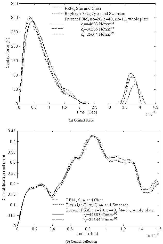 | Figure 6. Comparison of predicted contact force and central deflection histories of a[0/90/0/90/0]s plate impacted by a 7.5g mass of velocity 3m/s |
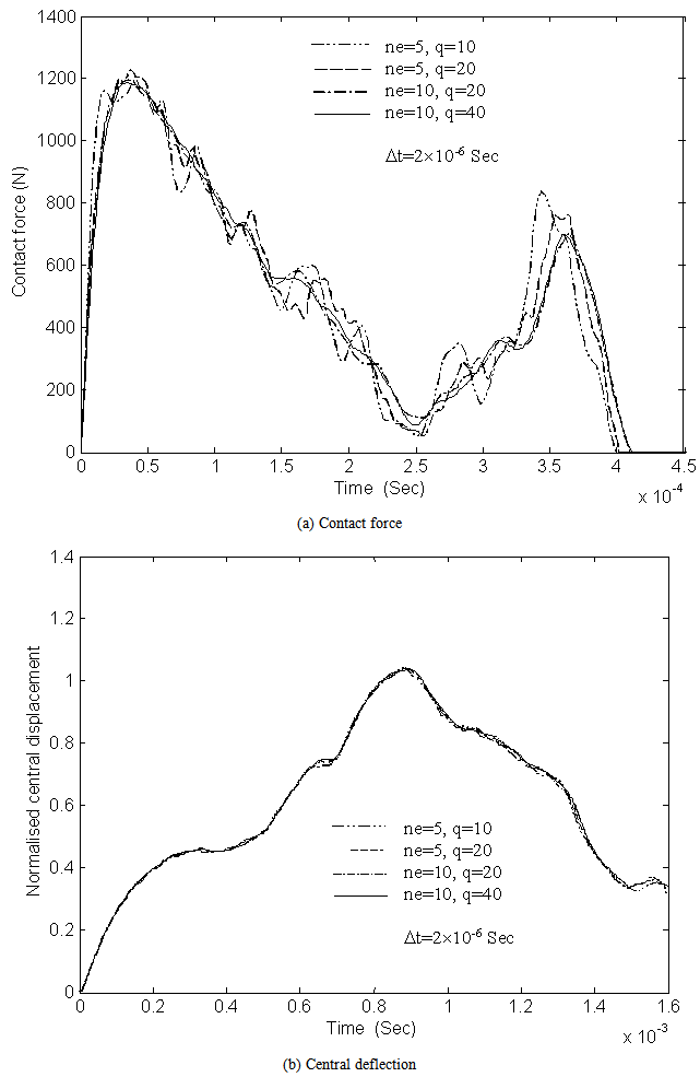 | Figure 7. Convergence with respect to plate mesh for the problem of a[0/90/0/90/0]s plate impacted by a 19.6 g mass of velocity 10 m/s |
5.2. Quasi-isotropic Plate Subjected to Drop-weight Impact
- Here consider the example of a steel drop-weight impact on a[45/0/-45/90]s quasi-isotropic plate of AS4/3502 graphite-epoxy which was studied by Ambur et al[31]. The dimensions of the experimental specimens were 254 mm long and 127 mm wide and the thickness of a single layer was 0.127 mm. The specimens were simply supported on all four edges and impacted on the plate centre at impact-damage-initiation threshold energy level of 0.6779J (6 in.-lb). The material properties of AS4/3502 are given asE1 = 137.8 GPa, E2 = 9.0 GPa, ν12 = 0.3,G12 =G13 = 6.0 GPa, G23 = 3.5GPa, ρ = 1570 kg/m3
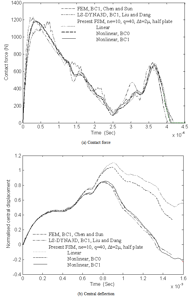 | Figure 8. Comparison of predicted central deflection history of a[0/90/0/90/0]s plate impacted by a 19.6 g mass of velocity 10 m/s |
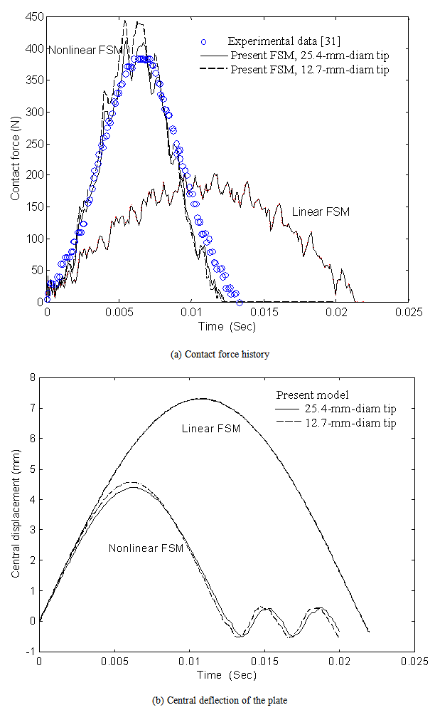 | Figure 9. Comparison of impact response of a[45/0/-45/90]s plate to drop-weight |
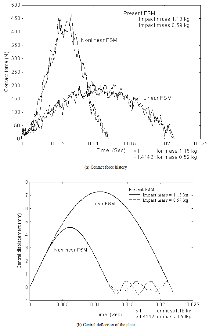 | Figure 10. Comparison of impact response of a[45/0/-45/90]s plate to masses 1.18kg and 0.59kg at a given impact energy of 0.6779J |
 . It is shown that during the impact contact period the results, both contact force and plate central-deflection, corresponding to those two masses are in a close agreement when using the time scales mentioned. This indicates that for a specified drop-weight impact event, the maximum contact force and the maximum plate deflection at the impact position depend on impact energy level but the contact period is dominated by the impact mass and a longer contact period arises from a bigger impact mass.
6. Concluding Remarks
- A Layerwise B-spline FSM has been developed for analysing the geometrically non-linear transient response of laminated composite plates to transverse low-velocity impact. To simplify the complicated contact analysis, a Hertz-type contact law has been incorporated into the finite strip model for accounting for the contact behaviour. The solution of the non-linear impact problem is sought using Newmark time integration scheme in conjunction with Newton-Raphson iteration. The geometrically linear transient analysis of the impact problem has been discussed briefly as well. With the neglect of impact-related terms, the developed procedure is capable of analysing plate transients under dynamic loading.The capability of the model has been used in a few applications including the impact response analysis of a plate subjected to relatively-high and low-velocity impact. It should be noted that the impact energy in both cases are low to avoid material damage and delamination which are not dealt in the present work. It has been indicated that the convergence behaviour of the impact dynamic problem is affected by the interaction of the plate and the impactor. Comparison of the results obtained from the geometrically non-linear analysis has been made with those of small-deflection solution and/or available results gained from finite element calculation and experiment. This comparison demonstrates the validity of the analysis procedure as well as the effect of geometric non-linearity on plate response and contact force. The results show that for a specified drop-weight impact event, the impact energy level dominates the maximum contact force and the maximum plate deflection at the impact position but the impact mass dominates the impact contact duration.