GH. Liaghat 1, 2, H. Shanazari 1, M. Tahmasebi 1, A. Aboutorabi 2, H. Hadavinia 2
1Department of Mechanical Engineering, Tarbiat Modares University, Tehran, Iran
2Material Research Centre, SEC Faculty, Kingston University, London, SW15 3DW, UK
Correspondence to: GH. Liaghat , Department of Mechanical Engineering, Tarbiat Modares University, Tehran, Iran.
| Email: |  |
Copyright © 2012 Scientific & Academic Publishing. All Rights Reserved.
Abstract
In this paper, based on Woodward model[1], an analytical model has been developed for perforation of projectile into ceramic composites targets. In the new model, contribution of different phases of projectile during perforation (erosion, mushrooming and rigid phase), modification of semi-angle of ceramic cone during perforation process, modification of the shape of the nose of projectile and changes in yield strength of ceramic during perforation are considered. The ballistic limit and residual velocity of projectile by presented model have a good agreement with experimental and other theoretical results of other researchers.
Keywords:
Penetration, Ceramic Armour, Analytical Model, Projectile, Layered Materials
Cite this paper: GH. Liaghat , H. Shanazari , M. Tahmasebi , A. Aboutorabi , H. Hadavinia , A Modified Analytical Model for Analysis of Perforation of Projectile into Ceramic Composite Targets, International Journal of Composite Materials, Vol. 3 No. 6B, 2013, pp. 17-22. doi: 10.5923/s.cmaterials.201310.03.
1. Introduction
Ceramic materials are widely used in armour systems as well as aircraft structures and military vehicles for the advantages of low density, high compressive strength, hardness and heat resistance. Response of ceramics to projectile impact and other types of high-speed loading conditions is an important issue for these applications. Ballistic performance of many types of ceramics was investigated in many experimental, theoretical and numerical studies. A review of penetration/perforation process of ceramic targets can be found in[2,3,4]. A great amount of these studies regarding ceramic targets subjected to high velocity impact investigate the behaviour of materials under impact load. The ceramic destroys the projectile tip, slows it down, and distributes the load over a large area of the back-up plate. The back-up plate supports the ceramic and brings the comminuted ceramic and projectile to rest. The back-up plate material is selected on the basis of structural, ballistic, and weight considerations. Kevlar, fibreglass, spectra, and aluminium are most commonly used as the backing material. The mechanical properties of a ceramic determine its ballistic efficiency. The hardness of the ceramic causes the erosion and disintegration of the projectile, thus, preventing further penetration. The armour plate is exposed to very high bending stresses; hence, the ceramic must have high flexural and tensile strength. If the fracture toughness of the ceramic is too low, the crack propagation might be too severe after the impact which could damage the ceramic significantly. This can reduce the degree of multihit protection offered by the ceramic armour system. Ceramics with lower density is preferred as it reduces the overall weight of the armour. An ideal armour ceramic material must have a combination of these desired properties and should also be easy to manufacture.Tate[5] has presented a model that is considered a basis for research in long rod penetration on thick targets. In Florence’s model[6], a global energy balance is proposed leading to the derivation of the ballistic speed limit. The Woodward model[1] investigates penetration mechanism considering the lumped mass approach. This model presents analytical solutions for calculation of velocity and residual mass of a projectile at any instant of time after impact.In 1991, Den Reijer[7] developed an analytical model based on Woodward work[1]. He proposed a set of governing equations to model the main physical mechanism during the penetration process.In 1998, Chocron and Galvez et al.[8] presented a model where the back plate of the armour is made of polymer composite material such as Kevlar/Epoxy. The model allows the calculation of residual velocity, residual mass, the projectile velocity and the deflection and strain histories of the back-up plate.In 1998, Zaera and Sanchez-Galvez[9] developed a new analytical model to simulate the ballistic impact of a projectile into ceramic/metal armour. This model is based on Tate[5] equation for the projectile penetration into ceramic tile. In this model, the values of residual velocity, residual mass and ballistic limit velocity, are consistent with the experimental results.In 1999 Fellows[10] developed Woodward's model for ceramic-faced semi-infinite armour.In 2010 Feli et al.[11] based on Zaera and Sanchez-Galvez[9] work presented an analytical model which employed the momentum equation to describe fragmented ceramic conoid. In this model, the ballistic limit and residual velocity of projectile have a good agreement with the experimental results.In the analytical models mentioned above, the mushrooming of projectile’s tip has not been included and its erosion during penetration has only been taken into account. Also the authors assumed that a conoid of comminuted ceramic with a semi-angle of about 650 is developed which pushes forward a circular area of metallic plate with dimensions equal to the base of the ceramic conoid.
2. Analytical Model
Using the lumped mass approach and according to Woodward[1] theory, the following equation can be formed. The equations of motion of the system shown in Fig.1 are: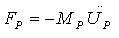 | (1a) |
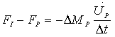 | (1b) |
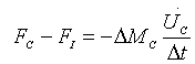 | (1c) |
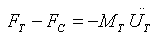 | (1d) |
Where F is force, M is mass, ∆t is the time incrementand ∆M is the change in mass.  and
and  are velocity and acceleration respectively, and subscripts P, I, C and T refer to penetrator, interface, ceramic and target respectively as shown in Fig.1.
 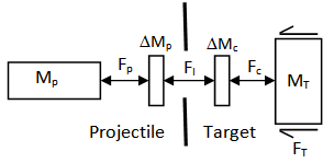 | Figure 1. Lumped mass model |
Penetrator is considered as a flat ended cylinder with cross sectional area A0. We can assume a column of penetrator and ceramic being squeezed out giving continuity equations of the form: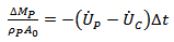 | (2a) |
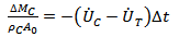 | (2b) |
where ρ is the material density.Constitutive equations for the failure or penetrator and ceramic can be established by requiring that for erosion of a column of material to occur, a value of flow stress, Y, must be exceeded, whether this is governed by uniaxial yield stress, hardness or some other strength measure.  | (3a) |
 | (3b) |
To solve the equations, elimination of  and
and  from the equations yields a quadratic which can be solved at each time step for the only unknown parameter, the penetrator mass loss
  . At each time step all other parameters can be updated and the solution then repeated. At first step, we have just velocity of projectile. The sign in equation (1b) is such that if
  is negative, thus there is a mass loss from the projectile. The sign in equation (1c) is such that if
 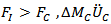 is positive, thus there is an increase in momentum of the ceramic which is moved out of the way.Woodward et al.[15] derived an equation for the work W, to dishing a plate of thickness b and flow stress YT to a displacement h,
 | (4) |
And it is shown that this equation can be used with reasonable accuracy to calculate the work done on dished back up plate from actual impacted ceramic composite targets.The resisting dishing force is obtained by differentiating equation (4) to give; | (5) |
Failure of back-up plate is considered for two cases. If ceramic erosion occurs during the acceleration phase, the effective kinetic energy Ek is equated to the work done by equation (4) i.e.: | (6) |
Where c is the reduced ceramic thickness after erosion, Dp is the projectile diameter. If the ceramic eroded to zero thickness during acceleration phase, the equation to determine whether the projectile would perforate is  | (7) |
The equations for the acceleration and failure phase will be solved and all penetration parameters such as residual velocity and mass of projectile will be determined.
3. Modifications on Woodward Model
Woodward model[1] has been further developed by considering different phases of projectile during perforation, i.e. erosion, mushrooming, rigidity, and applying interface force FI, modifying the shape of projectile nose, changing the semi-angle ceramic conoid and considering reduced compressive strength during penetration into target.
3.1. Different Phases of Projectile during Perforation
The projectile behaviour during impact, based on work by Reijer[7], is divided into three phases; a mass erosion phase, a mushrooming phase and a rigid phase (Fig. 2) dependent on the projectile velocity and the material strengths. Initially during high-velocity impact, the pressure at the interface between the projectile and ceramic will exceed the erosion strength of the projectile, and the projectile will erode. If the impact velocity is high enough, the erosion strength of the ceramic will be exceeded, and the ceramic will also erode.At high impact velocities the projectiles are eroded at ceramic/projectile interface. Therefore,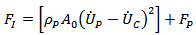 | (8) |
As the projectile velocity falls, the relative impact velocity  will fall below the plastic wave velocity, UPLAS. The relative displacement between the end of the projectile and the projectile ceramic interface can then start to be accommodated by plastic deformation of the projectile. Thus the projectile mushrooms as illustrated in Fig.2[10].
 | (9) |
Where LERO and LELA are the length of projectile at start of mushrooming phase and the length of projectile unaffected by the plastic wave, respectively.At some point in time the velocity of projectile will become equal to the velocity of the mushrooming stage which is penetrating the ceramic. At this point it is assumed that the projectile becomes a rigid body.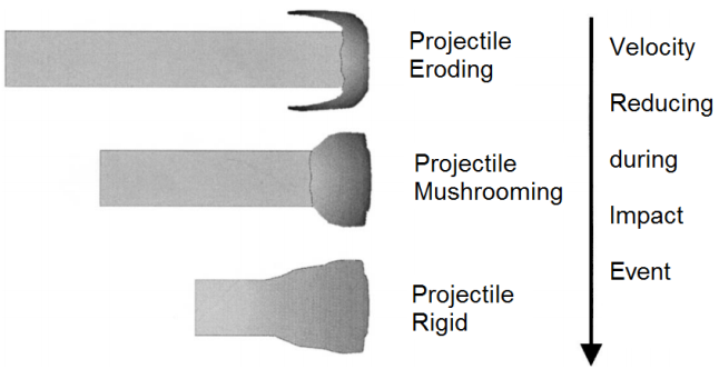 | Figure 2. Projectile behaviour during impact as projectile velocity falls[10] |
Projectile rigid stage: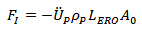 | (10) |
While in Woodward's model FI is only determined by equation (1).
3.2. Modification to the Projectile Nose Shape
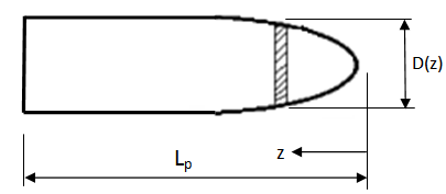
Next step is about shape of projectile tip. Woodward model considers flat ended projectile with perfect cylindrical shape, while actual projectile usually have ogival nose (Fig. 3). For non-cylindrical projectiles, equivalent diameter and length will be defined in Woodward model for such projectiles. Equivalent diameter Deq can be found by weighting each differential element of the projectile with its diameter[9],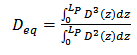 | (11) |
Where LP is the actual length of the projectile and D(z) the diameter for position z. Equivalent length Leq is determined from mass of the projectile: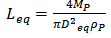 | (12) |
 | Figure 3. Ogival projectile |
3.3. Modification to the Conoid Semi-angle at Initial Impact
Changing in semi-angle ceramic conoid formed after impact is next modification on Woodward model[1]. The ceramic conoid semi-angle is an important parameter. There are different ideas about this angle[9,11,12]. Woodward[1] considered this angle about 68º (the angle formed in quasi-static state). According to different approaches and regarding the fact that in high impact velocities, because of high energy of projectile the projectile-ceramic interface force is more than ceramic erosion stress. Therefore the erosion of ceramic and then penetration of projectile into ceramic will occur. 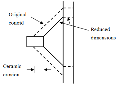 | Figure 4. The assumed reduction in effective dimensions of the conoid and backing plate as a result of ceramic erosion |
Both the erosion of ceramic and projectile are considered in Woodward model which makes the results closer to experimental data.When erosion of ceramic occurs, the effective dimensions of ceramic conoid reduced (see Fig.4). In the fact, when ceramic eroded, new ceramic conoids with smaller dimensions are formed. The higher impact velocity, results in smaller ceramic conoid. The semi-angle of ceramic can be approximated by equation (13). In this equation, this angle changes linearly between 68º in Woodward[1] model and 63º in Florence model[6]: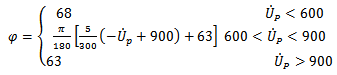 | (13) |
i.e. for impact velocities less than 600 m/s the semi-angle φ is equal 68º and for velocities more than 900 m/s is 63º and between them, changes linearly according to equation (13). Zaera[9] showed that by increasing the impact velocity the failure part increase and the dimensions of the cone decrease. Other researches verified the accuracy of equation (13).
3.4. Modification to the Conoid Semi-angle during Perforation at a Specified Impact
As mentioned before, in the Woodward model[1] when the ceramic erosion occurs, the effective dimensions of the ceramic cone decrease (Fig. 5). Sides of newly formed cones are parallel to the original cone. In words, we assume the angle remains constant during perforation process.The semi-angle φ is now changed in the newly formed cone and considered less than the initial value. Results of this model are closer to the experimental values. In other words, sides of newly formed cone are not parallel to the original cone.This change of the angle approximately can be found form: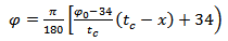 | (14) |
Where x is ceramic eroded length, tc is the thickness of ceramic and φ0 is the semi-angle of initial cone determined by equation 13. In the other words:● In case there is no erosion of ceramic the angle φ is as its maximum value.● In case there is highest possible erosion (total ceramic thickness) the angle φ is 34º (minimum value in Fellows[10] model).In summary the angle of a newly formed ceramic cone with semi-angle φ0 is determined by equation (13) and the angle will change during perforation according to equation (14).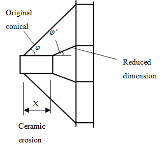 | Figure 5. Reducing the semi-angle ceramic cone in an impact |
3.5. Modification to Ceramic Strength after Impact
The last modification on Woodward model[1] is the determination of an expression for the compressive fragmented ceramic strength. Ceramic penetration strength is intensely lowered after fragmentation[13]. Furthermore, the back-up plate is deformed and some particles being expelled from the crater. More space for the fragments motion is available and thus the penetration resistance decreases[13]. If YCO represent the compressive strength of the intact ceramic plate and YC denotes a lower value after fragmentation, the expression for fragmented ceramic strength can be found: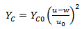 | (15) |
where u is the penetration velocity of projectile, w is the velocity of back-up plate and u0 is the initial penetration velocity of projectile.
4. Results and Discussion
The results of modified analytical model have been compared with other published analytical and experimental results. In order to show the effect of ceramic and back-up plate thickness, a target-projectile system has been considered[14] where the steel projectile is a small calibre 7.62AP with 8.3gr mass and its diameter is 7.62 mm. A two layer target has been made of Al2O3 alumina with variable thickness and Al6061-T6 as a back-up plate. Fig.6 shows, the ballistic limit velocity versus thickness of back-up plate for ceramic thicknesses of tc=4.05 mm. Present model shows good results in comparison with Woodward model. According to the figure in a specified ceramic thickness when the thickness of back-up plate increases, the ballistic limit velocity will increase. This is due to the fact that when the back-up plate thickness increases, more energy will be spent for bending and stretching the back-up plate. In a low thickness, stretching and bending forces are effective in the resistance to penetration of back-up plate but when thickness increases, the behaviour of back-up plate changes from petaling to plugging and shear forces increase.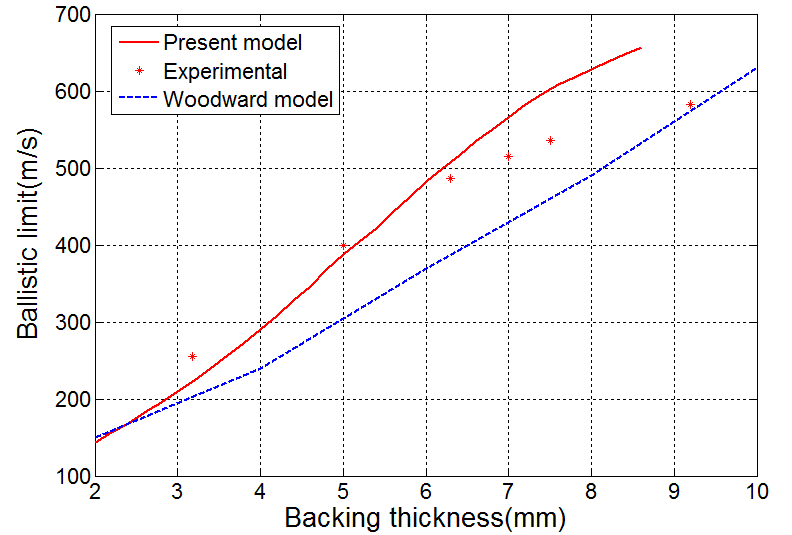 | Figure 6. Ballistic limit velocities for a surrogate steel 7.62AP projectile impacting AD85+Al6061-T6 with thickness of ceramic 4.05 mm |
Fig.7 shows, the ballistic limit velocity of modified analytical model versus ceramic thickness for two different backing thicknesses. According to this figure, the ballistic limit velocity of projectile will increase when the thickness of ceramic increases. In fact, when the thickness of ceramic increases, the projectile will remain longer behind ceramic tile due to more volume of fragmentation of ceramic and its velocity will be reduced. | Figure 7. Ballistic limit velocity versus ceramic thickness when a projectile impacting the two-layer target AD85+Al6061-T6 |
Fig.8 shows, ballistic limit of the analytical model in comparison with experimental data by Wilkins[14], Woodward model[1] and Zaera and Sanchez-Galvez model [9]. The modified analytical model is in good agreement with measured ballistic limit velocity than Woodward[1] and Zaera and Sanchez-Galvez[9] models. | Figure 8. Analytical and experimental results of ballistic limit of 7.62AP projectile impacting the target AD85+Al6061-T6 |
One of the most important parameters to determine the ballistic performance of ceramic composites is the ceramic hardness. To compare the effectiveness of hardness of ceramics, two types of ceramics, AD85 and B4C, with different hardness are considered for the same impact scenario (Fig. 9). According to the present model, if the energy of projectile is high enough so that the ceramic is eroded, the resistance to penetration is more when B4C is used. But when the energy of projectile is low enough so that the ceramic is not eroded there will be little difference between the ballistic performance of the two ceramics (AD85 and B4C). Fig. 9 shows that when the ballistic limit velocity increases due to increase in backing thickness, the difference between the behaviour of two types of ceramic will be more pronounce.The effect of decreasing compressive strength of the fractured ceramic conoid in the process of penetration is shown in Fig.10. In this figure, ballistic limit velocity in a target made of Alumina-Aluminium is compared in two states: first Yc is constant and second Yc is reducing during the penetration process according to equation (15). According to the present model shown in Fig.10, as result of decreasing compressive strength of ceramic during penetration process, the ballistic limit velocity will be decrease. Moreover for the higher impact velocity (higher ballistic limit velocity) it decreases more rapidly because of more erosion in ceramic. | Figure 9. Comparison of ballistic limit velocity of two type of ceramic with different hardness for the same impact scenario on the target with Al6061-T6 as a back-up plate |
 | Figure 10. Comparison of ballistic limit velocity for two compressive strength cases in a similar impact on the target with Al6061-T6 as a back-up plate: a) Constant and b) Reduced |
5. Conclusions
The modified model presented in this study is based on Woodward model[1] and it is a simple way to predict the penetration resistance of ceramic-metal targets and the results of this model are in good agreement with experimental data and other analytical models. The deformation of the projectile is modelled by lumped mass approach and ogival projectile tip and three phases for projectile behaviour, i.e. a mass erosion phase, a mushrooming phase and a rigid phase depending on the projectile velocity based on work by Den Reijer[7] are considered.In additionin this model modification of semi-angle of ceramic cone at initial impact and during perforation and reduction in the compressive strength of the intact ceramic plate after fragmentation of ceramic are considered. According to the modified model, when erosion of ceramic does not occur, there is a slight difference between ballistic performances of ceramics with similar thickness because of density of ceramics which determines the mass of material bounded by the cone crack. If ceramic eroded, with increase in hardness and thickness of ceramic, ballistic limit velocity will increase. In the presented model, change in semi-angle of ceramic cone has maximum influence on improving the accuracy.
Notation
 Diameter of base cone, base of cone after erosion and projectile, respectively
 Displacement of backing plate
 Mass
Mass Displacement, velocity, and acceleration, respectively
 Compressive strength of the intact ceramic plate andcompressive strength after fragmentation,
 respectively
 Subscripts: projectile, interface, ceramic and target, respectively
 Semi-angle of initial cone, semi-angle of cone after erosion, respectively
 Length of projectile at start of mushrooming phase and the length of projectile unaffected by the
  plastic wave
  Plastic wave velocity
 Ceramic thickness
 Ceramic eroded length
References
| [1] | Woodward, R. L., “A simple one-dimensional approach to modeling ceramic composite armor defeat”. Int J Impact Eng 1990;9(4):455-74. |
| [2] | Chen XW, Chen YZ, “Review on the penetration/perforation of ceramic targets”. Adv. Mech 2006;36 (1):1-19. |
| [3] | Liaghat GH., Shanazari H., “Analysis of perforation of projectile into ceramic composites”, J. of Amirkabir, 2005; 15(60/2):97-109. |
| [4] | LiaghatGH., Tahmasebi AbdarM., “Experimental and Theoretical Investigation of Perforation Process into Ceramic Targets and Presenting a Modified Theory”, MSc Thesis, TMU (2013). |
| [5] | Tate A. “A theory for the deceleration of long rods after impact”. J. Mech. Phys, Solids, 1967;14:387-99. |
| [6] | Felorence AL. “Interaction of projectiles and composite armour”. Internal Report, US Army, August 1969. |
| [7] | Den Reijer PC, “Impact on ceramic faced armours”. PhD thesis, Delft University of Technology; 1991. |
| [8] | Chocron Benloulo IS, Rodryquez J, Sanchez Galvez V. “A simple analytical model to simulate textile fabric ballistic impact behavior”, Textile Res J Tentative 1997 (July). |
| [9] | Zaera R. Sancez-Galvez V. “Analytical modeling of normal and oblique ballistic impact on ceramic/metal light weight armours”, Int J Impact Eng 1998;21(3):133-48. |
| [10] | Fellows N.A. “Development of impact model for ceramic-faced semi-infinite armour”. Int. J. Impact Eng; 1999:22;793-811. |
| [11] | FeliS., Alami Aaleagha ME. Ahmadi Z., “A new analytical model of normal penetration of projectiles into the light-weight ceramic-metal targets”. Int. J Impact Eng. 2010;37: 561-567. |
| [12] | Wilson D. Hetherington JG, “Analysis of ballistic impact on ceramic faced armour using high speed photography”. In: Proceeding of the lightweight armour system symposium. Cranfield: Royal Military College of Sience;1995. |
| [13] | Zhang Xiao-qing, Yang Gui-tong, Huang Xiao-qing, “Analytical model of ceramic/metal armour impacted by deformable projectile, Applied Mathematics and Mechanics”. (English Edition), 2006, 27(3):287-294. |
| [14] | Wilkins ML. “Mechanics of penetration and perforation”. Int J Impact Eng 1978;16:793-807. |
| [15] | Woodward R.L., O'Donnell R.G., Baxter B.J., Nicol B., Pattie S.D. “Energy absorption in the failure of ceramic composite armours”, Materials Forum, 1989,13(3):174-181. |
 Abstract
 Reference
 Full-Text PDF
 Full-text HTML