-
Paper Information
- Previous Paper
- Paper Submission
-
Journal Information
- About This Journal
- Editorial Board
- Current Issue
- Archive
- Author Guidelines
- Contact Us
American Journal of Polymer Science
p-ISSN: 2163-1344 e-ISSN: 2163-1352
2015; 5(1A): 28-39
doi:10.5923/s.ajps.201501.04
Self-Supported Lightweight Polyaniline Thin Sheets for Electromagnetic Interference Shielding with Improved Thermal and Mechanical Properties
 Abstract
 Reference
 Full-Text PDF
 Full-text HTML
Rakesh Kumar1, 2, 3, Seema Joon1, 3, Avanish Pratap Singh1, B. P. Singh2, S. K. Dhawan1
1Polymeric & Soft Material Section, CSIR-National Physical Laboratory, New Delhi, India
2Department of Chemistry, DCRUST Murthal, Sonepat, Haryana, India
3PDM College of Engineering, Bahadurgarh, Haryana, India
Correspondence to: S. K. Dhawan, Polymeric & Soft Material Section, CSIR-National Physical Laboratory, New Delhi, India.
| Email: |  |
Copyright © 2015 Scientific & Academic Publishing. All Rights Reserved.
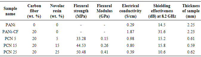
The present paper reports an approach to develop self-supported lightweight thin sheets of polyaniline-carbon fiber (PANi-CF) composite by compression molding using phenolic novolac resin as a binder, for their use in electromagnetic interference (EMI) shielding. PANi-CF composites were synthesized by in-situ chemical oxidative emulsion polymerization of aniline along with carbon fiber, using dodecyl hydrogen sulfate (DHS) as surfactant as well as dopant. Polyaniline-carbon fiber-novolac (PCN) sheets having thickness of ~0.6 mm were then prepared by hot pressing and thermal annealing, using different amount of novolac resin in order to optimize the thermal, mechanical, electrical and shielding properties. PCN composite sheets were characterized by FTIR, TGA and SEM. These sheets have shown flexural strength of 33.28-50.48 MPa, electrical conductivity of 0.39-0.98 S/cm and electromagnetic shielding effectiveness of 35.0 dB at 10.6 GHz frequency. So this work develops a methodology to fabricate lightweight self-supported conducting PCN sheets having good thermal, mechanical and electrical behavior and can be used to design shields of electronic equipments for protection of electromagnetic interference.
Keywords: Keywords PANi thin sheets, Carbon fiber, Mechanical strength, Electrical conductivity, EMI shielding
Cite this paper: Rakesh Kumar, Seema Joon, Avanish Pratap Singh, B. P. Singh, S. K. Dhawan, Self-Supported Lightweight Polyaniline Thin Sheets for Electromagnetic Interference Shielding with Improved Thermal and Mechanical Properties, American Journal of Polymer Science, Vol. 5 No. 1A, 2015, pp. 28-39. doi: 10.5923/s.ajps.201501.04.
Article Outline
1. Introduction
- Electromagnetic radiations are one of the deplorable byproducts of the accelerated growth in the field of electronics and telecommunication, aircraft technology, navigation, wireless systems [1-3]. The rapid proliferation of electronic devices has increased the vulnerability to electromagnetic interference (EMI). EMI consists of any unwanted disturbance that effect a circuit due to many superfluous radiated signals emitted from an external source carrying transient currents [4, 5]. The source of the emitted radiation may have frequency ranging from the lower power frequencies to the microwave region. The disturbances created by EMI may interrupt, obstruct or otherwise can cause unacceptable degradation of system or equipment performance in terms of partial or total loss of data. The compatibility of an equipment function in close proximity of other equipment is called as electromagnetic compatibility (EMC). These twin problems of EMI and EMC must be attended, otherwise, that can cause severe damage to communication system and safety operation of many devices. In fact, EMI shielding represents a way towards the enhancement of the electromagnetic compatibility. Now shielding of EMI is getting increasing attention in digital electronics and communication systems because of devices becoming increasingly sensitive, dense and ample. In addition, EMI shielding is of critical use due to the health concerns, such as symptoms of languidness, insomnia, nervousness, headache etc. on exposure to electromagnetic waves [6].Conventional approach for EMI shielding believes in the use of metallic materials in the forms of metallic sheets, meshes, plating coatings, which supply excellent shielding effectiveness (SE) [7]. High weight of metals is not desired in aerospace applications. Corrosion is another major drawback of metallic materials which reduces the SE of the shields, especially in joints [8]. Another approach to overcome the problems of weight and corrosion, came to existence is the use of various types of conducting composites comprising a non-conducting polymer matrix and conducting fillers such as metal particulates, metal fillers, carbon black and carbon fibers (CF). The major advantages of the polymer composites are their low fabrication cost and high strength to weight ratio. But these conventional polymer composites could not offer desired value of SE, especially in microwave range. CF and metal filled polyethylene composites are reported to have poor performance of EMI shielding [9]. Similar case has been reported for metal filled composites of polypropylene [10]. Now a days intrinsically conducting polymers (ICPs) and their composites along with their wide spread applications in organic light emitting diodes [11], polymer solar cells [12], antistatic coatings [13], and electrochromic devices[14] are also finding their application as shielding materials for electromagnetic radiations in low as well as high frequency range [2, 14, 15]. A lot of work has been reported based on the preparation and shielding properties of ICPs, their blends and composites. Composites based on polymers like hexagonal-ferrite/polymer, metal/polymer composites and single walled CNT-epoxy composites have been reported by many research groups for this purpose [16-18]. These composites of conducting polymer have prolonged their sphere and currently finding their application in EMI shielding technology [2, 14, 15]. ICPs are becoming increasingly available, but they are not common and tend to be poor in their processability, fabrication and mechanical properties. Although, ICPs may be used with or without filler for providing shielding for commercial application, yet, in the presence of conductive filler, an electrically conducting polymer matrix has the added advantage of being able to electrically connect the filler units that do not touch one another, thereby enhancing the connectivity and so improve the conductivity. In order for a conductive filler to be highly effective, it preferably should have a small unit size, a high conductivity (for shielding by reflection) and a high aspect ratio (for connectivity). Fibers are more attractive than particles due to their high aspect ratio. So EMI shielding is one of the main applications of conventional short carbon fibers [19].Among all ICPs polyaniline has attracted particular interest because of its unique structure and excellent properties like ease of preparation in aqueous medium, good thermal stability, good stability in air/environment, simplicity in doping [20], well-behaved electrochemical properties, and moderately high conductivity in the doped state [21]. The molecular structure of polyaniline is composed of alternatively reduced (–B–NH–B–NH–) and oxidized (–B–N=Q=N–) units where B and Q denote C6H4 rings in the benzenoid and quinoid states, respectively [22]. Polyaniline exists in four different forms namely leucoemeraldine, pernigraniline, emeraldine and conductive emeraldine salt. These forms refer to different oxidation states of polyaniline ([(–B–NH–B–NH–) y (–B–N=Q=N–) 1−y] x) where y = 1, 0.5, and 0, respectively. This shows that oxidant play an important role in controlling the structure and electrical properties which can be tailored according to the application. The use of strong oxidizing agent like ammonium peroxydisulfate (APS) and potassium dichromate resulted in high yield, conductivity and viscosity of polyaniline [23]. Another approach to improve the conductivity of PANi, is to prepare the polymer by chemical oxidative emulsion polymerization especially by using an anionic surfactant as a dopant, such as dodecylbenzene sulfonic acid, naphthalene sulfonic acid, sodium lauryl sulphate (SLS)/sodium dodecylsulfate (SDS), and bis-2-ethylhexyl sulfosuccinate sodium salt [24, 25]. Anionic surfactants may act as counter ions for conducting-polymer polycations, and the hydrophobic part of the surfactant molecules may adsorb on the produced conducting polymer, a surfactant thus becoming a part of the resulting material. The presence of surfactants improves the colloidal solubility of conducting polymers in organic solvents [26] and, consequently, also the processability [27]. It had been reported in the literature that the introduction of a surfactant during the preparation of ICP leads to an increase in the conductivity also [14, 15, 25]. Various types of composites consisted of such anionic surfactant doped PANi have been widely developed and used for various applications. However, there are few reports on composites based on PANi prepared in the presence of SDS (PANi/SDS), compared to the case of PANi/DBSA and PANi/NSA, although PANi/SDS synthesized by chemical or electrochemical polymerizations was recently closely investigated [24, 28-30]. The processability of PANi/SDS itself is greatly different from those of PANi/DBSA and PANi/AOT, because it shows low solubility/dispersibility for almost of all solvents or polymers in the similar manner as PANi/HCl, but PANi produced in micelles of SDS is having nanospherical structure and have good conductivity so may be used as a convenient material for shielding.A lot of work has been carried out to improve SE of different conducting polymers including PANi and its composites for their use in commercial as well as aerospace and military applications, but little work has been reported to improve their mechanical strength and processability. Moreover, little work has been reported for the fabrication of PANi composites in the form of thin sheets. In the present work PANi-CF composites were synthesized by in-situ emulsion polymerization using acidified sodium dodecyl sulphate (DHS) as surfactant as well as dopant and much attention has been paid to make self-supported resin based thin sheets (~0.6 mm thickness) of PANi-CF composite by thermal annealing during compression moulding technique using different amount of phenolic novolac resin as a binder. The composite sheets have shown good mechanical strength and thermal stability with sufficient SE values for their potential use in microwave shielding.
2. Experimental
2.1. Materials
- Aniline from Merck, India was freshly distilled before use. Reagent-grade sodium dodecyl sulphate (SDS, Himedia, India), ammonium peroxydisulfate (APS, Merck, India) and hydrochloric acid (Merck, India) were used as received. Polyacrylonitrile based carbon fibers (Toray-T-300-Japan) were chopped to get fiber size of 5-6 mm prior to use. Novolac (Phenolic resin, Pheno-organic, India) has been used as binder for making sheets of PANi-CF composites.
2.2. In-situ synthesis of PANi-CF Composite
- Synthesis of PANi-CF composite has been carried out by In-situ chemical oxidative emulsion polymerization. First 0.1 M SDS was dissolved in distilled water & homogenized for half an hour. To convert SDS to DHS, 0.1 M HCL is added to this aqueous solution of SDS until pH was maintained at 2-3. Chopped CF (20% by wt. of monomer, aniline) were added to this aqueous solution of DHS & further homogenized for 1 h. Appropriate amount of aniline (0.1M) was added to the above solution and homogenized again for 1 h to form micelles (emulsion) of aniline-CF with DHS. The emulsion so formed was transferred to two walled stainless steel reactor and polymerized at -3℃ through chemical oxidative polymerization by drop wise addition of 0.1M APS and continuous stirring. The polymerization completed in 6-7 h. The polymer composite so formed was filtered by means of buchner funnel of G-4 specification and washed repeatedly with distilled water to remove any amount of interior left out & then dried at 60-70℃. Finally it was crushed in pixel and mortar to get PANi-CF composite powder. In this composite PANi act as a conducting matrix and CF act as a reinforcement or filler material to improve mechanical as well as electrical properties. DHS is used as surfactant as well as dopant. By the similar route pristine PANi doped with DHS was also synthesized for comparative study.
2.3. Preparation of Self-Supported Thin Sheets of PANi-CF Composite
- Self-supported free standing thin sheets of PANi-CF composite were prepared by compression moulding using novolac as a binder. For this, first PANi-CF composite powder was mixed and grinded with novolac powder for 2 h using Retsch “PM-400” planetary-ball mill in tungsten carbide jars. Further to increase the homogeneity of this mixture, it was dispersed in ethanol (10% by wt. of mixture) by means of ultrasonication for 3 h. After that the solvent, ethanol was evaporated at 50℃ and the sample was then dried at 70℃. Thin sheets of PANi-CF composite were prepared by compression moulding at 100℃ temperature and contact pressure which results in crosslinking of novolac resin in the polymer matrix and excess of resin squeezed out after doing its action. After getting the post curing temperature of 150℃ for 2 h, PCN sheets having thickness ~0.6 mm were then ejected out from the mould upon cooling up to room temperature. By this method samples having different ratios of PANi-CF: novolac (95:5, 85:15, 75:25) have been prepared to see the effect of novolac on mechanical, thermal, electrical and shielding properties of PANi-CF composites. Further loading of Phenolic novolac resin have been avoided because the conductivity and SE start lessening. Composite sheets so prepared were abbreviated as PCN5, PCN15 and PCN25.
2.4. Materials Characterization
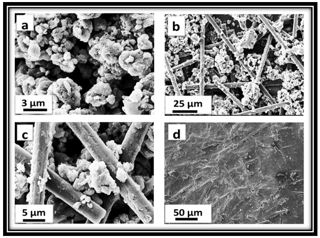
- The morphology of PCN composites were examined by scanning electron microscope (SEM, Zeiss EVO MA-10). Thermal stability of the samples were carried out by thermogravimetric analyzer (Mettler Toledo TGA/SDTA 851e) under inert atmosphere (flowing N2 gas) in the temperature range of 25-900℃, at a uniform heating rate of 8℃/min. UV-vis absorption studies were carried out on Shimadzu 1601 Spectrophotometer in the wavelength range of 200-1100 nm (see supporting information). Fourier transform infrared (FTIR) spectras were recorded on Nicolet 5700 in the wavenumber range of 4000-500 cm-1. Mechanical strength of PCN sheets were explained in terms of measurement of flexural strength and flexural modulus by three point bending test based on ASTM D790 [28] using an Instron Universal Testing Machine (model 4411) at a crosshead speed of 0.5 mm/min. The specimens having length (l) = 70 mm, width (b) = 20 mm and thickness (t) ~ 0.6 mm were taken to measure this three-point test. The support span length (L) between the two supports of specimen was 20 mm. In this test the failure occur at the center of the specimen span since this is the location of maximum stresses. The specimen was placed centrally with its long axis perpendicular to the loading nose and supports and load was applied until the specimen breaks. The record of mid-span maximum deflection and the maximum applied load F on the specimen were used to calculate the flexural strength (σ) which represents the highest stress experienced within the material at the moment of its rupture and was calculated in Megapascal (MPa) by using the following equation:
 | (1) |
 | (2) |
 | (3) |
3. Results and Discussion
3.1. Mechanism for the Formation of PANi-CF Composites
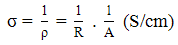
- Synthesis of PANi-CF composite was carried out by in-situ chemical oxidative emulsion polymerization at -3℃. The overall reaction process for the formation of PANi-CF composite by the emulsion polymerization pathway using SDS as surfactant as well as dopant is shown in Fig. 1. In the first step SDS surfactant is converted to DHS by treating with equimolar HCl (0.1M) solution. Second step involves the addition of chopped CF, and then upon high speed homogenization DHS surfactant formed emulsion in water system. The micelles containing CF formed at critical micelle concentration, in which the polar head group of the DHS on the outer surface of the micelles stabilizes the system where micro micelles are also absorbed on the polar surface of the CF. The incorporation of CF into DHS emulsion strongly affects the micelle aggregation number and second critical micelle concentration. The shape of a micelle is the function of molecular geometry of the surfactant molecules and solution conditions such as surfactant concentration, temperature, pH and ionic strength [32]. The third step is the addition of aniline monomer in to the emulsion system, followed by slow addition of APS initiator (oxidant) in the fourth step. Here a spherical micelle phase has been formed via cooperative interaction of aqueous APS solution and DHS in water. Aniline and APS molecules due to their hydrophobic nature diffused in to the micelles and surrounded by hydrophilic sulfonate, –SO3H unit. Addition of oxidant APS leads to the formation of cationic free radicals, which combines with second monomer to form dimer, which on further oxidation and combination with another cation radical forms a termer and ultimately to a long chain of polymer. The properties of polymer composites depends on various factors like method of preparation, type & amount of oxidant and dopant used. Slow addition of oxidant at low temperature controls the chain linearity and internal defects in the polymer structure. The several reports indicates that better separation, reasonable yield and conductivity were obtained when SDS is employed as surfactant as well as dopant and in the ratio of ~ 1:1 (monomer: surfactant molar ratio) [24, 30, 33, 34]. The final structure of PANi in scheme 1 is showing that the surfactant molecules have become a part of the resulting material due to ionic interaction between the polymer and the surfactant. In this way PANi-CF composite having spherical shaped PANi has been prepared whose morphology is shown further in SEM images.
 | Figure 1. Schematic representation for the synthesis of PANi-CF composite |
3.2. Morphology of Composites
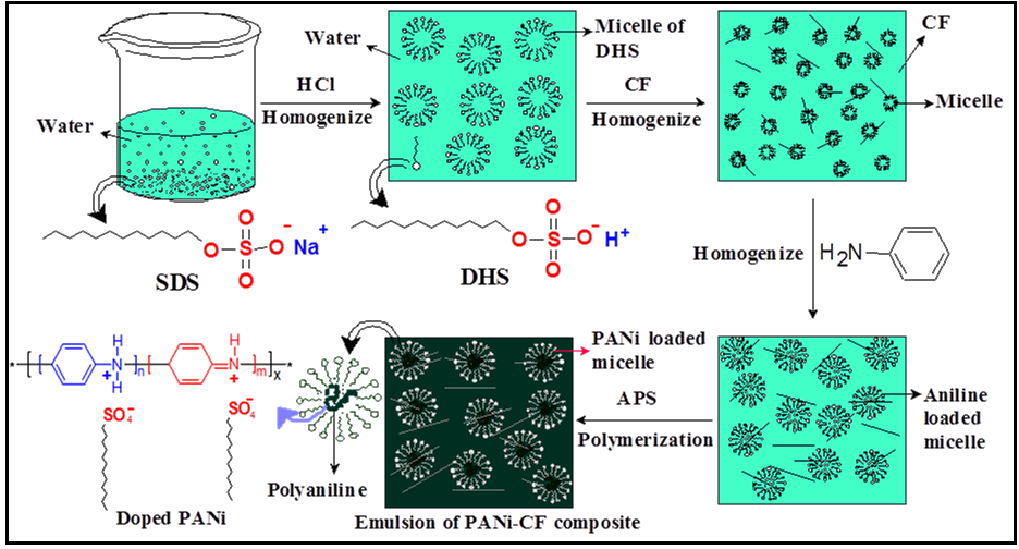
- Fig. 2 demonstrates the SEM micrograph of PANi, PANi-CF composite and PCN25 sheet. Fig. 2a displays the spherical morphology with porous in nature of PANi due to dopant DHS. It has been observed that the morphology of the microstructures is strongly affected by the structure and concentration of the dopant, and oxidant, as well as the preparation conditions. The observed spherical structure of PANi due to DHS used as surfactant plus dopant is similar to previous reports [24, 34]. Fig. 2b & c showed the distribution of carbon fibers in PANi-CF composite, which shows that the conducting fillers have connected the conducting polymer matrix as most of the carbon fibers are longitudinally elongated which improves the mechanical strength as well as the conducting path in the composite sheet. High resolution image (Fig. 2c) displayed that PANi particles are also deposited on the surface of carbon fibers. This implies that the interaction between polymer molecules and carbon fibers conquers the van der Walls interaction between carbon fibers, with the effective interaction between the π-bonds in the aromatic ring of PANi and CF should strongly facilitate the charge transfer reaction between the two components [35]. So in this composite carbon fibers can offer a good mechanical support to PANi and also ensure the electronic conduction in the composite. Fig. 2d displays the signature of carbon fiber in the PCN sheet. This figure shows that novolac used as binder in the composite sheet has increased the connectivity.
 | Figure 2. SEM images of (a) PANi, (b & c) PANi-CF powder and (d) PCN15 sheet |
3.3. Thermal Analysis
- The thermogravimetric analysis (TGA) of the PANi, PANi-CF composite and PCN sheet was carried out in order to see the effect of CF and novolac on the thermal stability of PCN sheets. It is generally known that three weight-loss steps are observed in the TGA curve of PANi [25]. The first weight-loss observed up to 110°C should be due to loss of residual water molecules/moisture entrapped in the polymer moiety [15, 25]. The second stage observed within the temperature range of 182–300°C should be related to removal of dopant molecules from the polymer structure [29]. The weight-loss observed after the removal of the dopant molecules should correspond to the complete degradation and decomposition of the polymer main chain [25, 36]. The thermogram of PANi prepared using DHS (Fig. 3a) shows that polymer is thermally stable up to 182°C. A weight loss of 5.4% is observed up to 110 °C which is due to the loss of water molecules/moisture. From 182-300°C, the loss is 31.70% due to the removal of dopant DHS. From 300-900 °C there is continuous weight loss of 28.90% which may be due to degradation of polymer backbone. And total weight loss observed is 66%. On comparing the thermal behavior of PANi with the thermal behavior of PANi-CF composite (Fig. 3a), the thermal stability of the composite increased up to 210°C. Initial weight loss of 2.6% is observed up to 110°C which may be due to the loss of water molecules entrapped in the polymer matrix. From 210°C to 300°C, weight loss observed is 27.41%, which is accounted due to the loss dopant from the polymer composite. A weight loss of 31.2% is observed, due to polymer backbone degradation, from 300-900°C, but weight loss in this section is slow as compared in case of weight loss in PANi-SDHS/DHS. Total weight loss in case of PANi-CF composite is 63.71%. Further, when we compare these thermograms with the thermogram of PCN25 (Fig. 3a), it is observed that the thermal stability of the composite sheet has been increased up to 230°C. Initial weight loss due to loss of water molecules in this case is very less that is 0.6% because the sheet was already thermally cured at 150°C. Further the weight loss from 230-300°C is 16.37% which is due to partial leaching of the dopant from the polymer composite matrix. A very less weight loss due to removal of dopant in this case (as compared to thermogram of pristine PANi) showed that novolac has made some kind of ionic interaction with the PANi structure. From 300-900°C a weight loss of 29.19% is observed due to degradation of polymer backbone as well as due to removal of novolac resin from the composite sheet. In this case polymer degradation is slow. The weight loss observed nearly from 480-650°C is due to partial leaching of novolac resin from the polymer composite matrix. So Fig. 3a showed that thermal stability of polymer is enhanced due to incorporation of CF as filler and further increased due to novolac resin used as binder. The binder might have increased the interaction of dopant and CF with the polymer molecules and hence increased the thermal stability.
3.4. Fourier-Transform Infrared Spectroscopy (FTIR)
- A typical infrared spectrum of PANi-CF composite powder is shown in Figure 3b. It shows major characteristic peaks (vibrational bands) at 1560, 1470, 1290, 1110 and 791 cm−1, which are similar to the standard PANi reported in the literature [37] the bands at 1560 and 1470 cm−1 are due to ring stretching of quinoid and benzenoid, respectively. The C-N stretching bands of an aromatic amine appear within the range of 1300-1200 cm−1. In the region of 1020-1170 cm−1 aromatic C-H in-plane-bending modes are usually observed. For PANi, a strong band characteristically appears at 1110 cm−1, which has been explained as an electronic band or a vibrational band of nitrogen quinine. According to Han and co-workers [24] this peak around 1120 cm−1 can be assigned to in-plane-bending vibration of C–H (mode of N=Q=N, Q=N+H–B, and B–N+H–B; Q = quinoid ring, B = benzenoid ring) which should occur during the protonation. The small shift in the peak position and the intensity might be due to the different dopant levels of the resulting PANI. A band at 791 cm−1 is due to C-C out-of-plane ring deformation. In addition to these normal bands of PANi, the presence of bands at 2920 cm−1 and 2850 cm−1 are related to asymmetric and symmetric aliphatic C-H stretching vibrations, respectively [38], indicates the existence of alkyl substituent of DHS in the polyaniline chain, which is used as dopant as well as surfactant in the polymerization reaction. Furthermore, in the cases PANI prepared in SDS, the presence of SO3− group is confirmed by appearance of a band around 570 cm−1 attributed to degenerate bending mode of the SO3− group [34] Comparison of spectra of PANi-CF, with spectra of PCN5, PCN15 and PCN25 sheet samples (Fig. 3b) confirms the presence of novolac resin in the PANi-CF composite. The slight shift in the main peaks of sheets was observed due to some ionic interaction between novolac resin and PANi chains. Appearance of especially, no new band in FTIR spectra of PCN composite indicates that there is no chemical reaction between these constituents.
3.5. Mechanical Strength, Conductivity Measurement and Shielding Measurement
- PANi-CF composite mixed with novolac resin when compression moulded leads to the formation of free standing PCN composite sheets which have better mechanical, electrical and shielding properties.
3.5.1. Electrical Conductivity and Mechanical Strength
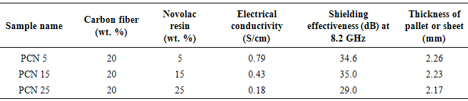
- On comparing the properties of the pristine PANi with its different composite sheets shown in Table 1, it was observed that incorporation of carbon fiber in the polymer matrix during polymerization dramatically increases the electrical conductivity of PANi-CF composite. Introduction of CF facilitate the charge transfer process between the two components of the composite and thereby enhances the conductivity by formation of conductive network. Varshney et al. reported that electrical conductivity and mechanical strength increases with increase in CF loading in PPy matrix. Some reports are also there in the literature where improved mechanical and electrical properties has been achieved by incorporation of carbon nanotubes and carbon fiber in the conjugated polymer matrix [17]. In the present work CF loading in the polymer matrix is fixed (20% by wt.) and novolac percentage is varied in the PANi-CF composite to get self-supported thin sheets having better mechanical strength, sufficient electrical conductivity and shielding effectiveness. On comparing the absolute values of conductivity (Table 1), it is concluded that electrical conductivity decreases when PANi-CF composite was physically blended with novolac resin because the insulating novolac resin hinders the free flow of electrons in the conducting polymer composite. Fig. 3c showed that conductivity keeps on decreasing with increasing the novolac percentage in the composite. When PCN composites were transformed in the form of thin sheets electrical conductivity again increases (See supporting information) as the novolac resin make some kind of ionic interaction with carbon fibers and binds the fillers tightly with the polymer matrix, thereby enhancing the connectivity of fillers and matrix. Moreover, during the thermal curing of the sheets at 150℃ for 2 h in compression moulding, the excess of novolac resin squeezed out after doing its action.
|
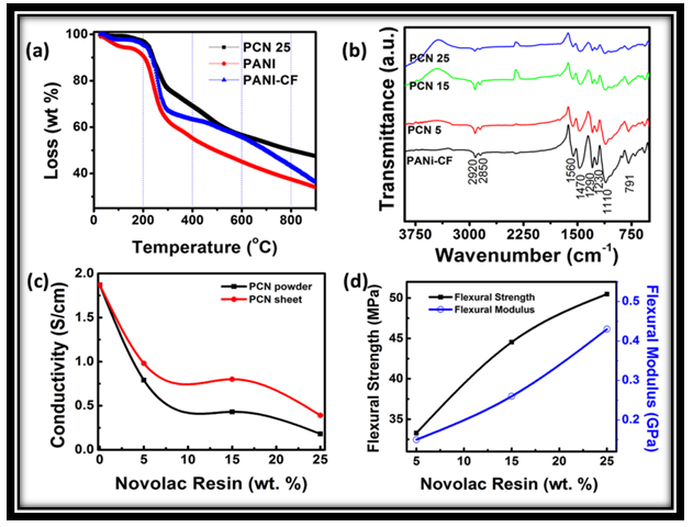 | Figure 3. TGA of PANi, PANi-CF and PCN25sheet (a), FTIR spectra of PANi-CF, PCN sheets (b) variation of conductivity as a function of wt.% of novolac resin in PCN composite powder and PCN sheets (c), and variation of flexural strength and flexural modulus as a function of wt. % of novolac resin in PCN sheets (d) |
3.5.2. Electromagnetic Shielding
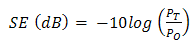
- The EMI shielding effectiveness of a material is defined as the ratio of transmitted power to the incident power and is given by
 | (4) |
 | (5) |
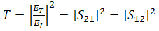 | (6) |
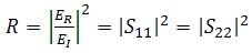 | (7) |
 | (8) |
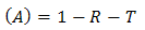
 . Therefore, the effective absorbance
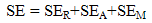
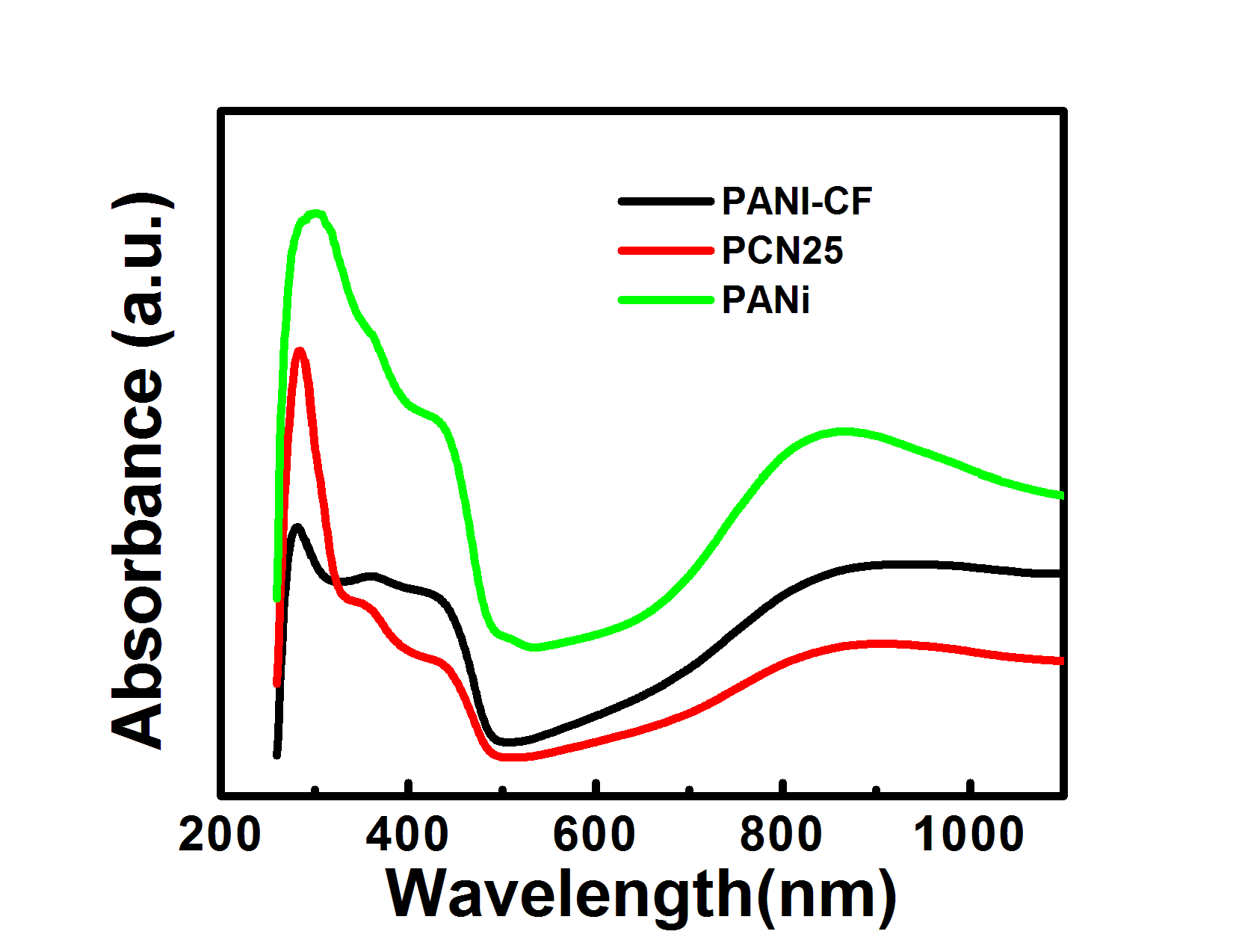
  can be described as Aeff = ( 1 − R – T) / (1 – R) with respect to the power of the effective incident EM wave inside the shielding material. It is convenient to express the reflectance and effective absorbance in the form of −10 log (1 – R) and −10 log (1 – Aeff) in decibel (dB), respectively, which give SER and SEA as [39]
 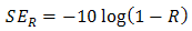 | (9) |
 | (10) |
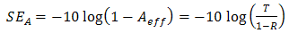
 | Figure 4. reflection coefficient (a), absorption coefficient (b), transmission coefficient (c) and absorption efficiency (d) of the as synthesized PCN sheets |
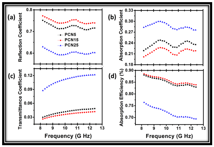
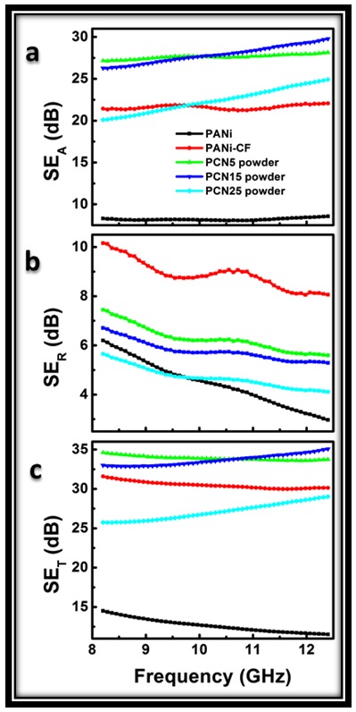
 | Figure 5. Variation of shielding effectiveness SEA (a), SER (b), SET (c) with frequency in 8.2-12.4 GHz, showing effect of novolac concentration in PCN sheets and SET of PCN15 sheets with different thickness (d) |
4. Conclusions
- Self-supported thin sheets of PANi-CF have been successfully prepared by compression moulding, using novolac resin as binder. Dispersion of conducting filler in the polyaniline matrix improves the mechanical as well as electrical properties of sheets. By improving the filler matrix interaction, novolac resin has improved the mechanical properties of PCN sheets without affecting the shielding properties significantly. Novolac resin & carbon fiber jointly enhance the flexural strength of PCN sheet up to 50.48 MPa, Flexural modulus up to 0.41 GPa. Thermal stability of PCN sheet has been found to be 230℃. Self-supported thin sheets of PANi-CF composite with 15% loading of novolac have greater shielding effectiveness, (15.8 dB at 0.6mm thickness) in 8.2-12.4 GHz frequency range. In addition, multiple PCN sheets have shown SE up to 35dB at a critical thickness of 3.0 mm. It is believe that the polymer composite sheets could be promising candidate for next generation building block material in microwave shielding with vast utility in aerospace applications due to their lightweight, good thermal and mechanical properties.
ACKNOWLEDGEMENTS
- The authors wish to thank Prof. R.C. Budhani, Director NPL and Prof. Pratibha, Chairperson, Department of Chemistry, DCRUST for their keen interest in the work. The authors thank Dr. R.B. Mathur for the measurement of mechanical properties and K.N. Sood for recording SEM micrograph.
Appendix
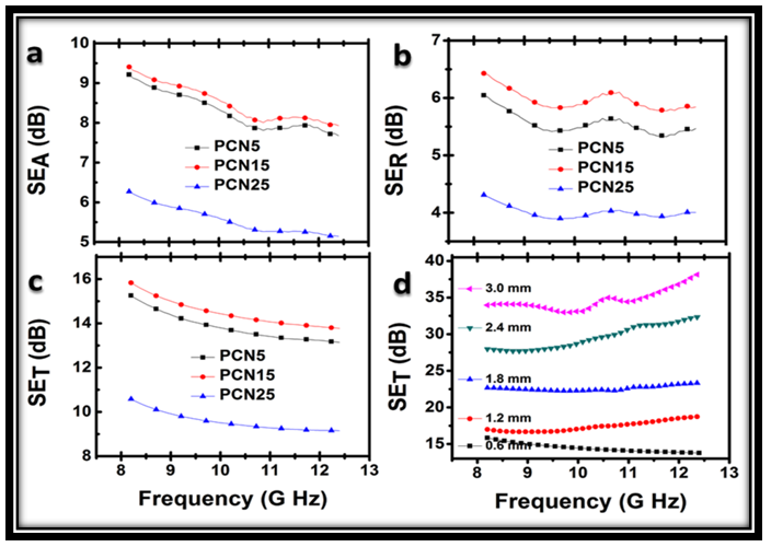
- Supporting Material Document1 UV-vis spectroscopyUV-vis absorption spectrum of PANi, PANi-CF and PCN25 composites were shown in fig. s1. The study was carried out by preparing the samples in N-methyl pyrolidone as solvent, which changes the polymer in deprotonated (undoped) form. To make the polymer again protonated (doped) 1N HCl is added to the samples up to color changes from blue to green (doped PANi). Doped PANi shows three characteristic absorption bands at 320–360, 400–420 and 740–800 nm wavelengths. The first absorption band arises from π- π* electron transition within benzenoid segments. The second and third absorption bands are related to doping level and formation of polaron, respectively. But position of the bands depends on the dopant and nature of alkali or solvent in which UV study is carried out. In the acidic region, three distinct absorption bands of the green protonated polyaniline are observed at 350, 430 and 810 nm.
 | Figure S1. UV-vis spectra of PANi, PANi-CF and PCN25 Powder sample |
 | Figure S2. Variation of SEA, SER and SET with frequency for PANi, PANi-CF, PCN composites in powder form before transforming into sheets |
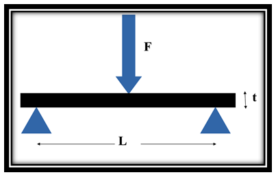 | Figure S3. Schematic representation of three point flexural test measurement |
|