-
Paper Information
- Next Paper
- Previous Paper
- Paper Submission
-
Journal Information
- About This Journal
- Editorial Board
- Current Issue
- Archive
- Author Guidelines
- Contact Us
American Journal of Polymer Science
p-ISSN: 2163-1344 e-ISSN: 2163-1352
2015; 5(1A): 1-6
doi:10.5923/s.ajps.201501.01
Studies on Nanocomposites of Polyaniline Using Different Substrates
 Abstract
 Reference
 Full-Text PDF
 Full-text HTML
Ashok. K. Sharma1, Gunjana Chaudhary1, Indu Kaushal1, Umesh Bhardwaj2, Ajay Mishra3
1Department of Materials Science & Nanotechnology, D.C.R University of Science & Technology, Murthal, India
2Department of Chemistry, Hindu Post Graduate College, Sonepat, India
3Department of Applied Chemistry, University of Johannesburg, South Africa
Correspondence to: Ashok. K. Sharma, Department of Materials Science & Nanotechnology, D.C.R University of Science & Technology, Murthal, India.
| Email: |  |
Copyright © 2015 Scientific & Academic Publishing. All Rights Reserved.
Nanocomposites of polyaniline (PANI) were prepared in different molar ratios on Carbon nanotubes (CNTs) and Graphene nanosheets(GNs) substrates, separately. The nanocomposites were synthesized by in-situ oxidative polymerization method and characterized to understand the nanocomposites formation of the materials. Physicochemical characteristics of prepared nanocomposites were evaluated by means of UV-Visible, FTIR and X-ray diffraction (XRD) techniques. The morphology of the nanocomposites was studied by scanning electron microscopy (SEM). It was found that CNTs and GNs with PANI formed uniform nanocomposites with distinct morphologies. Enhancement in the electrical conductivity of the nanocomposites was observed with the addition of substrates to the PANI.
Keywords: Nanocomposites, Polyaniline, Carbon nanotubes, Graphene nanosheets
Cite this paper: Ashok. K. Sharma, Gunjana Chaudhary, Indu Kaushal, Umesh Bhardwaj, Ajay Mishra, Studies on Nanocomposites of Polyaniline Using Different Substrates, American Journal of Polymer Science, Vol. 5 No. 1A, 2015, pp. 1-6. doi: 10.5923/s.ajps.201501.01.
Article Outline
1. Introduction
- Conducting polymers (CPs) and their composites have been intensively studied as nanostructured organic materials. They have attracted attention in the fields of fundamental and applied researches. This growing interest arises due to their unique properties or combination of properties, achieved by confining the dimensions and their reduced structural disorder. Their synthesis and chemical modification offer numerous possibilities and potential for commercial applications owing to their relatively high conductivity, unique surface morphology with high specific surface area, environmental stability etc [1-7]. Among the various available organic conducting polymers like polythiophene (PT), polyaniline (PANI), polypyrrole (PPy), poly(3,4–ethyledioxythiophene) (PEDOT) and poly(p-phenylene vinylene) (PPV) etc. polyaniline (PANI) has gathered considerable attention owing to its fascinating electronic conductivity, simple synthesis and processabiliy, environmental stability, good electrochemical properties derived from conjugated π-electron system and suitability for fabricating composites with various binders and substrates [8-11]. However, conducting polymers have poor mechanical strength and lower cycle life which limits their use in energy storage devices like supercapacitors. Researchers have overcome this problem by fabricating polymer composites and hybrid assemblies [12-14].Carbon nanotubes (CNTs) are 1-dimensional nanomaterials with carbon framework. They have received a great interest for the development of novel materials and functional devices. It is well known that the properties of conducting polymers, include charge storage, cycle life, electrical conductivity and mechanical strength are greatly enhanced with the introduction of carbon materials like CNTs into conducting polymers [15-16]. This is associated with the unique mechanical, thermal, electrical, electronic and optical properties of CNTs, which make them widely studied filler or substrate materials. The composite formation from the conducting polymers and CNTs produces a hybrid material possessing the inherent properties of each component with a synergistic effect [17-19]. In addition, the thin layer of conducting polymers provides an efficient functionality for a variety of potential applications owing to effective charge drainage /transfer. These advanced materials have diversified applications in sensors, batteries, supercapacitors, solar cells, actuators, electromagnetic shielding and electronic devices [20].Graphene nanosheets (GNs), a 2-dimensional monolayer of sp2 bonded carbon atoms, have been recognized as a promising, cost effective and high quality alternative to CNTs. Graphene nanosheets exhibit outstanding electrical conductivity at room temperature due to their very high electron mobility [21]. They also possess larger specific surface area and excellent mechanical properties comparable with CNTs [22]. The doping of PANI with graphene nanosheets result in remarkable increase in stability, high degree of ordering, enhanced charge mobility and mechanical strength of the composites. Such encouraging features provide these nanocomposites with a wide range of applications in many technological aspects such as lithium ion batteries, nanoelectronics, supercapacitors, sensors, catalysts etc [23]. However, preparing composites with a homogeneous dispersion of individual graphene nanosheets with in the smooth thin polymer layer is quite a challenge.In the present work, we report the synthesis of the nanocomposites of PANI on CNTs and GNs substrates by oxidative polymerization and their comparative study on the physicochemical, morphological and conductive properties.
2. Experimental
2.1. Materials
- Aniline (99%) was purchased from E. Merck Ltd. (India) and was vacuum distilled. GNs was purchased from XG Science and multiwalled carbon nanotubes having diameter 10-12 nm and length 1µm was procured from Nanocyl (Belgium). All other chemicals like hydrochloric acid (HCl), ammonium peroxydisulfate (NH4) S2O8 (APS), ethanol, N,N-dimethyl formamide (DMF) was obtained from S.D. Fine Chem. Ltd. All the chemicals were of analytical grade and were used as received. Aqueous solutions were prepared in deionized water.
2.2. Synthesis of Composites
- Nanocomposites of PANI with CNTs and GNs were prepared by in-situ oxidative polymerization using APS as oxidant. Aniline was first distilled under vacuum to remove the oxidation impurities. 0.1 g of CNTs was dispersed in 1M HCl and then ultrasonicated for 4 hours for dispersion. Varying amounts of aniline monomer (0.1M, 0.25M, 0.5M) using 1M HCl as solvent, was added to the flask containing ultrasonicated CNTs. The mixture was again ultrasonicated for 2 hours. Freshly prepared APS solution in 1M HCl was added dropwise to the aniline-CNTs mixture while maintaining stirring for 5 hours. The ratio of monomer to oxidant 1:1 was taken and temperature of the reaction mixture was maintained at 0-5°C. The resulting solution was filtered and washed with water and methanol thoroughly to remove the unreacted oxidant and low molecular weight oligomers. The product was dried in vacuum oven at 60°C. Same procedure was followed for the preparation of composites of PANI with taking 0.1g GNs. PANI was also prepared as above where 0.25 M of aniline was dissolved in initial polymerization solution. The PANI-CNTs and PANI/GNs nanocomposites with different monomer concentration of aniline will be designated as concentration of aniline in parenthesis CPA1 (0.1 M), CPA2 (0.25 M), CPA3 (0.5 M) and GPA1 (0.1 M), GPA2 (0.25 M), GPA3 (0.5 M) respectively.
2.3. Characterization
- Infrared spectrum (KBr pellet) was recorded by using Fourier transform infrared spectrophotometer (Perkin Elmer, 90776) for chemical structural identification of the prepared composites. The UV-Visible spectrum of the composites was recorded using Shimadzu UV–(2450) Spectrophotometer. The ordered structures of the composites were studied by XRD method. X-Ray diffraction data was obtained on (Phillips Xpert Pro) with CuKα radiation (1.54060A) by applying 45KV voltage. Surface morphology of the composites was obtained by scanning electron microscope (SEM) (Carl Zeiss EVO 40 and EVO 50, Germany). Conductivity measurements were carried out using two – Probe resistivity measurement system (RIGOL DM3068).
3. Results and Discussion
3.1. FTIR Spectra
- Figure 1 shows the FTIR spectrum of PANI, PANI/CNTs and PANI/GNs nanocomposites. The spectrum of PANI shows peak at 3434 cm-1 which is attributed to N-H stretching vibrations. The bands near 1600cm-1 & 1453cm-1 shows the quinoid and benzenoid ring vibrations, respectively [13]. The absorption band at 1293.60cm-1 is assigned to C-N stretching of secondary aromatic amines. The strong band at 1124cm-1 is a measure of degree of electron delocalization and hence it is characteristic peak of PANI conductivity [24]. On incorporation of CNTs in PANI the peaks at 1600 cm-1, 1453.56cm-1 and 1125.63cm-1 are shifted to 1588.64 cm-1, 1462.45cm-1 and 1116.75cm-1 respectively. The red shift observed in the nanocomposites indicates the conversion of benzenoid structure to polaron structure in the PANI chains. Also, there is a increase in the intensity of peaks. This shows effective degree of electron delocalization owing to the interactions between CNTs and PANI [24- 25]. On comparing the spectra of PANI and PANI /GNs nanocomposites, similar peaks are also observed in the spectrum of PANI/GNs nanocomposites at 3440 cm-1, 1583 cm-1, 1483 cm-1, 1304 cm-1, 1133 cm-1, 1013 cm-1. The peaks observed at 1585cm-1and 1297 cm-1are red shifted and all peaks are observed with increased intensity indicating that there is interaction between PANI and GNs enhancing the degree of delocalization of PANI [26].
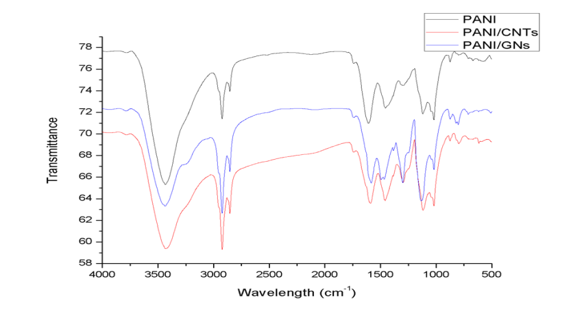 | Figure 1. FTIR spectrum of PANI, PANI/CNTs (CPA1) and PANI/GNs (GPA1) |
3.2. UV-Visible Spectroscopy
- The UV-Visible spectrum of the prepared PANI and its composites are recorded in (DMF) and illustrated in Figure 2. In the spectrum of PANI absorbance bands near 340nm, 463nm and 641 nm are observed , which are attributed to π- π* transition in benzenoid rings, polaron - π* electronic transition and exciton like transition from the benzenoid rings to the quinoid rings, respectively that further confirms the formation of emeraldine form of PANI [27-28]. PANI/CNTs nanocomposites show one band at 273 nm and other band which is red shifted at 355.75 nm. A broad band between 600-800 nm is observed which indicates charge transfer interactions between PANI and CNTs that attributes to conductivity [29-30]. The bands in PANI/GNS nanocomposites are also appeared at 327 nm, 443nm and 633 nm. This indicates interaction of PANI with GNs [31-32].
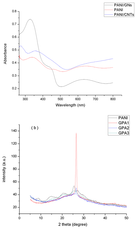 | Figure 2. UV- Visible spectrum of PANI/GNs (GPA1), PANI and PANI/CNTs (CPA1) |
3.3. X-Ray Diffraction
- The structure of the composites was also determined by powder X-Ray diffraction technique and displayed in Figure 3. The main peaks in the PANI XRD pattern are located at 2θ = 8.9°, 15.0°, 20.4°, 25.5°, 27.0° which correspond to the (001), (010), (011), (020) and (200) crystal planes of PANI in its emeraldine salt form, respectively [32-33]. Nanocomposites of PANI-CNTs show peaks similar to PANI and the peaks intensity is also close to that of PANI. For CPA1 the only peak characteristics of PANI is observed at 25.9°. The characteristics peaks of PANI became prominent as the concentration of aniline increases in the nanocomposites. No additional crystalline peak is observed indicating that crystal structure of PANI is maintained in the nanocomposites. For the nanocomposites GPA1 and GPA2 the peaks of PANI at 8.9°, 15.0°, 20.4° disappeared with only the peak at 26.6° existing which indicate that GNs has a strong interaction with the benzene rings of PANI. GPA3 nanocomposite show all the peaks observed for PANI. The XRD results confirmed the formation of nanocomposites and indicate that PANI and its nanocomposites has crystalline structure.
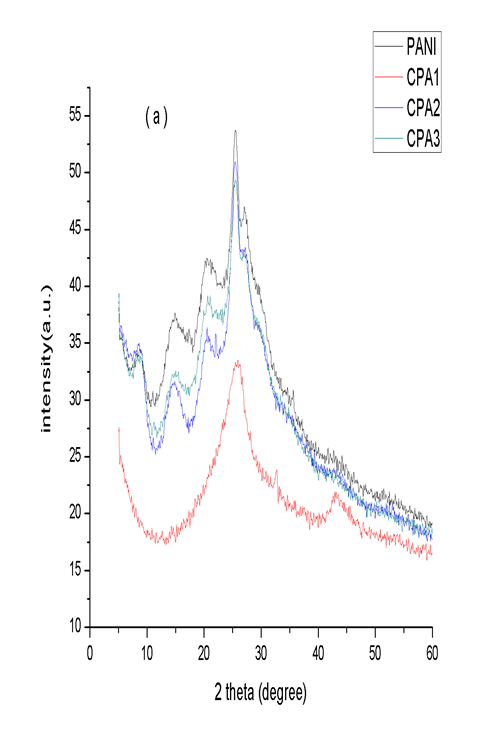 | Figure 3. a) XRD spectra of PANI, CPA1, CPA2 and CPA3 and b) XRD spectra of PANI, GPA1, GPA2 and GPA3 |
3.4. Scanning Electron Microscopy (SEM)
- Figure 4 shows the SEM images of neat PANI, CNTs, GNs and their nanocomposites. The neat PANI shows the formation of agglomerated and irregular granules of PANI along with nanofibers growing from the surface. The average size of these granules is in the range of 100 nm and of nanofibers is 40 nm. After in-situ polymerization of PANI onto CNTs, the surface of the CNTs become rough, indicating the deposition of PANI over CNTs. Compared with neat PANI, the composites are in the tubular form, which is much ordered than that of PANI granular form. The diameter of the PANI/CNTs nanocomposites became larger than pristine CNTs and it increases with increasing the aniline concentration in the initial polymerization solution [30, 34]. The SEM images confirmed the nanolayer deposition of PANI on the surface of CNTs. GNs in figure 4 displays lamellar structure. Composites GPA1 shows uniform coating of PANI in the form of small rods on the surface of GNS which is completely different from neat PANI morphology. This reveals that GNs supports the uniform adsorption of aniline molecules by the electrostatic forces of attraction. When APS was added into the ultrasonicated reaction mixture of GNs and aniline the adsorbed aniline molecules were initiated to polymerize from the adsorbed sites and started growing which resulted in the formation of these small rods [35]. On increasing the concentration of aniline in GPA2 and GPA3 it was found that compact and non-uniform layer of PANI has been coated with the formation of interconnected fibers [36]. This indicates that on increasing the initial concentration of aniline monomer while keeping the concentration of GNs constant, PANI particles did not get sufficient GNs as template and they escaped from the surface of GNs and get agglomerated. Therefore, GPA1 having most uniform PANI deposition results in highest conductivity whereas GPA3 shows least conductivity among the three composites. Similarly among the composites of PANI/CNTs, CPA1 shows highest conductivity having the thinnest deposition of PANI layer while CPA3 with thickest coating of PANI have the lowest conductivity.
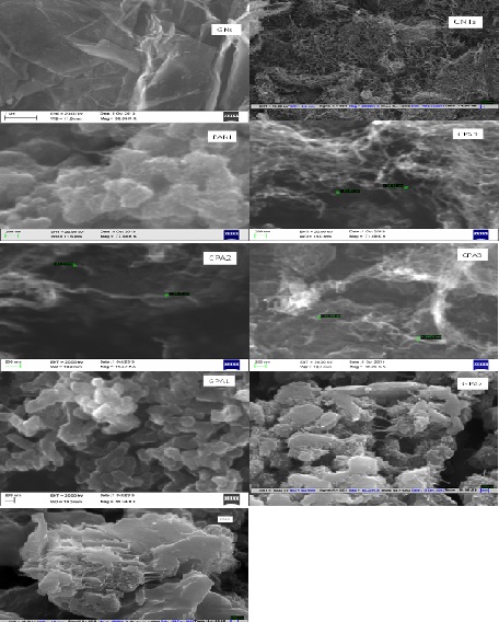 | Figure 4. SEM images of GNs, CNTs, PANI, CPA1, CPA2, CPA3, GPA1, GPA2 and GPA3 |
3.5. Conductivity Measurements
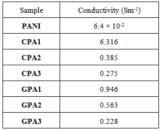
- The DC conductivity of neat PANI and its nanocomposites with CNTs and GNs was determined by pressed pellets using two- probe resistivity measurement system. The values of conductivity for nanocomposites have been listed in Table 1. The nanocomposites showed relatively high electrical conductivity compared to that of neat PANI. The enhanced conductivity indicated the formation of conductive networks between the quinoid rings of PANI and CNTs / GNs substrates which facilitates delocalization of π-electron and leading to enhanced conductivity [30, 32, and 37]. The maximum conductivity of 6.316 Sm-1 was observed for CPA1 and 0.946 Sm-1 for GPA1 which is higher by order of 2 and 1 respectively, than neat PANI. Although the conductivities of nanocomposites is higher than the pristine polymer but the concentration of aniline monomer in the initial polymerization solution had a pronounced effect on con ductivity. It is noticeable that conductivity of nanocomposites decline with increment in the molar concentration of aniline monomer. It could be due to the thickness of the coating of conducting polymer increases which adversely affect the overlapping of the carbon pz orbitals and valence orbitals of polyaniline. This influence the electron charge transfer resulting in the decline in conductivity of the synthesized nanocomposites [38-39].
|
4. Conclusions
- A series of nanocomposites involving polyaniline (PANI), Carbon nanotubes (CNTs) and Graphene nanosheets (GNs) have been successfully synthesized by oxidative polymerization. FTIR and UV-Visible characterizations confirmed the existence of PANI in doped state in both series of the nanocomposites. XRD data revealed the crystalline nature of the polymer and its nanocomposites. SEM confirmed the uniform deposition of PANI thin film over CNTs/GNs substrates which resulted in higher conductivities of these nanocomposites. These materials can be potential candidates for applications like sensors, batteries, supercapacitors, solar cells, electromagnetic shielding and electronic devices.
ACKNOWLEDGEMENTS
- Authors are thankful to the TDT Division of Department of Science & Technology, Government of India for providing financial assistance in the form of major research project.