-
Paper Information
- Next Paper
- Previous Paper
- Paper Submission
-
Journal Information
- About This Journal
- Editorial Board
- Current Issue
- Archive
- Author Guidelines
- Contact Us
American Journal of Fluid Dynamics
p-ISSN: 2168-4707 e-ISSN: 2168-4715
2015; 5(3A): 12-18
doi:10.5923/s.ajfd.201501.02
Effects of Under Expansion Level on Sonic Turbulent Jets Propagation
 Abstract
 Reference
 Full-Text PDF
 Full-text HTML
Mrinal Kaushik 1, Prashanth Reddy Hanmaiahgari 2
1Department of Aerospace Engineering, Indian Institute of Technology, Kharagpur, India
2Department of Civil Engineering, Indian Institute of Technology, Kharagpur, India
Correspondence to: Mrinal Kaushik , Department of Aerospace Engineering, Indian Institute of Technology, Kharagpur, India.
| Email: |  |
Copyright © 2015 Scientific & Academic Publishing. All Rights Reserved.
In the present study, the effects of under expansion level on the propagation of sonic turbulent jets issued from the circular and elliptic nozzles have been investigated experimentally. The sonic jets drawn from the circular nozzle with exit diameter of 10 mm and elliptic nozzle with aspect ratio 2:1 are studied at the nozzle pressure ratios (NPR) at 2.5, 3.5 and 4.5. Since the correctly-expanded state of the sonic jets is approximately closer to NPR 2.5, hence at NPRs 3.5 and 4.5, the jet is in under expanded state at the nozzle exit. The core length is measured in terms of centerline pressure decay and waves present are analyzed using shadowgraph technique. It is seen that both circular and elliptic jets core lengths increases with increase of levels of expansion, however, the waves present in elliptic jet core are found to be weaker in strength as compared to the circular jet. The shadowgraph images confirm the formation of a strong Mach-disk at the highest tested NPR of 4.5 in both circular and elliptic jets.
Keywords: Elliptic jet, Jet core length, Pressure gradient, Axis-Switching, Flow visualization
Cite this paper: Mrinal Kaushik , Prashanth Reddy Hanmaiahgari , Effects of Under Expansion Level on Sonic Turbulent Jets Propagation, American Journal of Fluid Dynamics, Vol. 5 No. 3A, 2015, pp. 12-18. doi: 10.5923/s.ajfd.201501.02.
Article Outline
1. Introduction
- The jet withno pressure imbalanceis called free turbulent jet which hasa large axial velocity gradient present within a thin region in the radial direction. In other words, high velocity fluid is surrounded by a stationary fluid, causing the formation of mixing layer at their interface, also called the shear layer, where transition to turbulence occurs. In the turbulent jets, gradients of mean velocity, turbulence intensities and turbulent stresses are negligible in the axial direction compared to the radial direction. Flow inside the jet is highly turbulent in nature, where a strong mixing takes place due to the presence of eddies of multiple length scales. The turbulent eddies penetrate into the stationary fluid surrounding the jet due to intermittency and ambient fluid is entrained into the turbulent region. Due to the entrainment of the surrounding fluid and strong mixing within the jet, the shear layer (mixing layer) widens rapidly in the streamwise direction and velocity gradients in the radial direction decrease in the streamwise direction. The enlargement of the jet in the streamwise direction affects decrease of time averaged velocity of the jet at its centerline. The turbulence in the jet is self-similar, where the length scale is radius
 of the jet at any section and velocity scale is the maximum time averaged velocity taken at the jet centerline. i.e.,
  is a function of
  where
where  time averaged streamwise velocity at any radial distance
  from the jet centerline,
  is radius of the jet at that section. Similarly, Reynolds stresses are also functions of
  These functions are independent of distance from the jet origin, therefore turbulent jets are called as self-preserving turbulent free jets. Another important feature of the free turbulent jets is the occurrence of the maximum Reynolds stresses where time averaged mean velocity gradient is maximum. But, all these characteristic are typically exhibited by a subsonic jet only, which is always correctly-expanded.But, it is well known that unlike subsonic jets, the sonic jets may be either correctly-expanded and/ or underexpanded, which is highly turbulent in nature. It is due to the fact that in the previous case there does not exists any pressure imbalance but in later case pressure imbalance may play its role depending upon then nozzle operating pressure ratio. The pressure imbalance at the nozzle exit, generate a complex shock-cell structure in the jet core region. The underexpanded state leads to the formation of expansion waves at the jet exit which extend to the free jet boundary, and get reflected as weak compression waves. These compression waves coalesce to form the intercepting shocks in the interior of the jet and thus, the core of the underexpanded jet is dominated by periodic shock-cell structures. Further, it is also established that for an efficient mixing of a free jet with the environment fluid, the mass entraining large scale vortices and mixing promoting small scale vortices should be in optimum proportion. However, identifying this optimum promotion is physically impossible, but this difficulty can be overcome by manipulating the size of the mixing promoting vortices [1]. From the vortex theory, it can be seen that the asymmetric jets shed the vortices of mixed size in comparison to their circular counterpart. In circular jets, the curvature is same across the jet boundary; therefore, the mixing is not rapid. On the other hand, in asymmetricjets due to their continuous variation in radius of curvature of the nozzle exit, shed the vortices of continuously varying size. These mixed size vortices promote both large-scale mass entrainment and small-scale mixing. The circular jets can be made asymmetric by controlling them. The control of jets can be broadly classified into two categories, the first one is the active control requiring an auxiliary power source whereas, the other passive control strategies are based upon geometrical modifications of the nozzle exit, which alter the flow development downstream of the nozzle relative to a conventional circular nozzle. In the past, many studies have been carried out on passive controlled jets such as, notches, grooves, tabs, cross-wire, etc., which makes the jet non-circular [2-10]. Several researchers have focused their studies on underexpanded jets to understand the complex shock cell structures. The shape of these shock structure becomes highly asymmetric when the jet exits from the non-circular orifice/nozzle exit geometries [11-14]. As a result of this, flow structures of different sizes form at the jet boundary and the jet spreads differently along different planes. This differential spread rate, the major and minor axes of elliptic jet switch after a certain distance downstream of the nozzle exit. The axis-switching phenomenon has been reported by many researchers in the past. Hussain and Husain, (1989) [15], observed that the location and number of axis-switching were strongly dependent on the initial conditions of the jet. Quinn, (1989) [16], observed two axis-switches of the major and minor axes and found that the jet attains an axi-symmetric shape at about 30 equivalent slot diameters downstream of the exit plane. Ho and Gutmark, (1987) [17], even reported three axis-switching in elliptic jets. The asymmetric jets are also drawnby nozzles with non-circular cross-section such as elliptic, rectangular, triangular, etc. The studies on non-circular jets show that the jet produces fine scale mixing at the corners or high curvature regions and is good suction creators at the low curvature/flat side regions resulting in high entrainment. Elliptic jets with smooth and continuous variation in radius of curvature fall between circular and highly non-circular (such as, rectangular, triangular) jets. Due to this smooth and continuous variation in radius of curvature, vortices generated at the exit will be of continuously varying size. These mixed size vortices promote both large and small-scale mixing. Whereas in circular jets, the curvature is same across the jet boundary, therefore the mixing is not as rapid as in elliptic jets. Gutmark et al(1991) [18], studied an elliptic jet of aspect ratio 3:1 and found enhanced mixing characteristics of the elliptic supersonic jet compared to a circular supersonic jet at underexpanded conditions. Passive control of fuel-air mixing using asymmetric jet exit geometry is an attractive pollution abatement technique [19]. For instance, the injection of longitudinal and azimuthal vortices in the shear layers from an elliptic co-flow can control the mixing of fuel and air, because these vortices are formed in the elliptic jet as a result of asymmetric self-induction of the vortex ring structures. The asymmetry causes instability in the flow field at the jet exit. Hence, an asymmetric jet tends to remove its instability by becoming symmetric downstream. This occurs as the major axis becomes small and the minor axis becomes large in order to become symmetric leading to axis-switching. Gollahalli et al (2002) [19], studied the effects of elliptic co-flow on the structure of a propane jet flame. The results were compared with the measurements from the experiments on the same burner in a circular co-flow. They found that, the elliptic co-flow flame produced less soot than the circular co-flow flame. Gutmark et al (1989) [20], found that, the elliptic jets burn 10% more efficiently than circular jets as a consequence of better mixing of fuel and air. Yoon and Lee (2003) [21], investigated the near field structure of an elliptic jet using stereoscopic particle image velocimetry and reported that the total entrainment rate of the elliptic jet was larger than that of the circular jet. Quinn (2007) [22], showed that mixing in an elliptic jet issuing from a sharp-edged orifice plate is higher than in elliptic jets issuing from contoured elliptic nozzles and in round jets. Chauhan et al (2015) [23], have compared the centerline pressure decay of 2:1elliptic sonic jet issuing from an orifice and a convergent nozzle under favorable pressure gradients. In this study they have varied the nozzle pressure ratios (NPR) from 2 to 5, in steps of one. They found that except at NPR 2 which is a correctly-expanded state, the decay is found to be faster for elliptic nozzle than elliptic orifice at all other NPRs. Though, the researchers have studied the mixing characteristics of elliptic jets at a length but they did not quantify the efficacy of elliptic jets over their circular counterpart. With this motivation, the present study aims at evaluating the efficacy of jet issuing from 2:1 elliptic nozzle has been investigated experimentally, in the presence of favorable pressure gradients. To quantify the mixing enhancement the Pitot pressure are measured along the jet centerline and the waves prevailing in the sonic jet coreareanalyzed using the shadowgraph optical flow visualization method.
 2. Experimental Methodology
- The brass made circular nozzle and sonic elliptical nozzle of aspect ratio 2:1, have been used for investigations. The equivalent diameter of the nozzle is found to be 10 mm. The schematic diagram of circular and elliptic nozzles is shown in Figure 1.
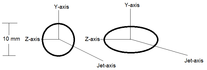 | Figure 1. Schematic diagram of circular and elliptic nozzles |
3. Results and Discussion
- It is understood that the sonic jet core consists of a large number of compression and expansion waves which are non-simple waves and change the Mach number of the flow passing through them. As a result, the Mach number at every local point assumes different values. Therefore, it is a usual practice to use the Pitot pressure distribution measured as it is in the non-dimensional form to characterize the jet field; such as the jet core length, shock-cell length, the acceleration zones, the characteristic decay and the fully developed zone. The Pitot pressure
 distribution measured along the jet centerline (X-axis) has been non-dimensionalized with the settling chamber stagnation pressure
  The axial distance
  has been made non-dimensional with the nozzle exit equivalent diameter
3.1. Centerline Pitot Pressure Decay
- Soon after exiting the nozzle, due to shearing action between high momentum jet and almost stagnant surrounding fluid, the large scale eddies are generated at the jet boundary. These large scale vortices, which have shorter life span, are responsible in engulfing surrounding zero momentum fluid into the jet. In this mixing process, these vortices breakdown into large number smaller eddies, responsible for mixing promotion. The jet-centerline Pitot-pressure decay is a measure of jet mixing with the entrained fluid mass. The decay can clearly show the extent of sonic jet core, which is defined as the axial distance up to which the nozzle exit velocity remains unaffected for subsonic jets and the axial extent up to which pressure fluctuations prevails for sonic jets [1]. The non-dimensional jet-centerline pressure decay plots of the elliptic jet of aspect ratio 2:1 and the circular jet, at NPRs 2.5, 3.5 and 4.5 are given in Figures 2(a)-(c). Since, the sonic jet at NPR 2, is almost correctly-expanded (pe/pb = 1) and thus at NPR 2.5, the jet is in moderate underexpanded state at the nozzle exit (Figure 2(a)). This implies that the waves prevailing in the core are weak in nature. It is also seen that the jet core for both elliptic and circular jets extends upto
 therefore; there existsa small pressure imbalance at the nozzle exit. However, the waves present in the elliptic jet are weak in nature, which is a direct evidence of enhanced mixing owing to its capability in shedding vortices of mixed size. The jets become almost fully developed beyond
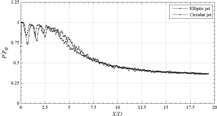 | Figure 2(a). Centerline pressure decay at NPR 2.5 (underexpanded) |
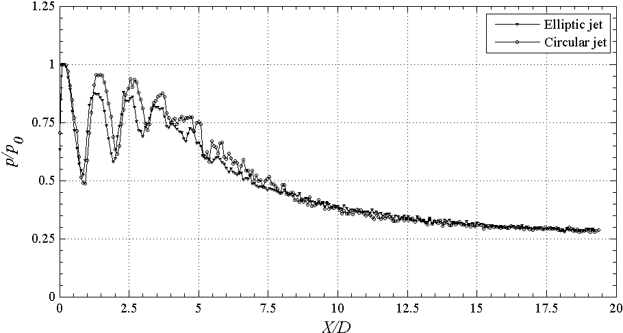 | Figure 2(b). Centerline pressure decay at NPR 3.5 (underexpanded) |
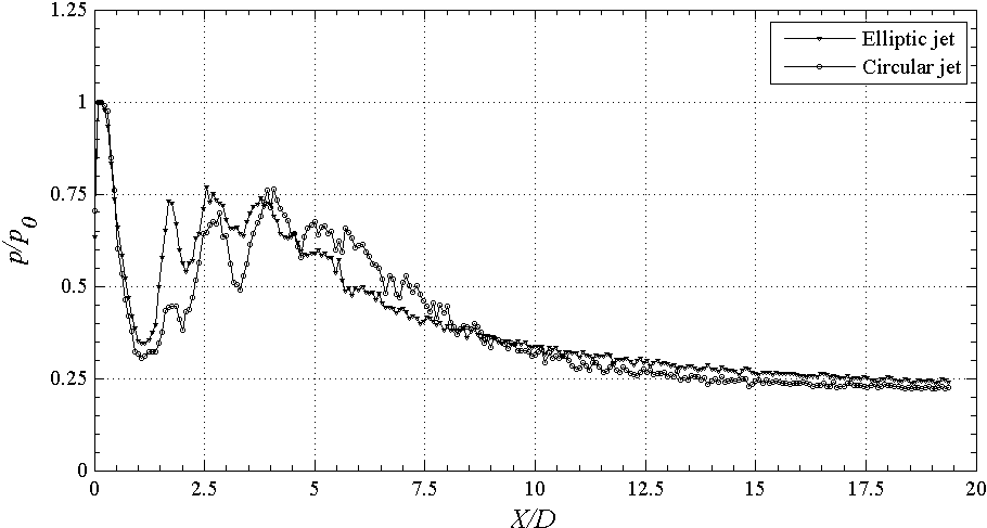 | Figure 2(c). Centerline pressure decay at NPR 4.5 (underexpanded) |
3.2. Shadowgraphic Flow Visualization
- The waves prevailing in the elliptic and circular jets flow fields are visualized with shadowgraph technique. The images recorded with a still camera are presented in this section. For the elliptic jets, the images are taken in the directions along the major axis and normal to major axis of elliptic nozzle. The shadowgraph pictures of the flow field from NPR 2.5, 3.5 and 4.5, are shown in Figures 3(a)-(c). Since, all the investigated NPRs of the present study correspond to underexpanded state of the jet, the expansion fans form at the edge of the nozzles. These expansion waves extend to the jet periphery and get reflected as compression waves due to unlike reflection of waves. These compression waves coalesce to form the intercepting shock in the interior of the jet, and thus the core of the underexpanded jet is dominated by periodic shock cell structure.Due to moderate underexpansion level at NPR 2.5, generates weak waves in the core of ellipticsonic jet as seen in Figure 3(a). These weak waves cause some light bright and dark regions in the jet core. The shorter core lengths and weaker shock-cell structure, as observed in the centerline pressure decay plots can beseen in the shadowgraph pictures as well. From these images, it can also be seen that the shock-cell structures diverge along the major axis plane and converge along the minor axis plane (Figures 3(a)). The differential spread rate in these two directions generates shear and leads to the faster decay of jet.
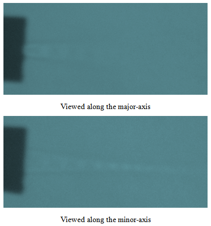 | Figure 3(a). Shadowgraph images of sonic jet at NPR 2.5 |
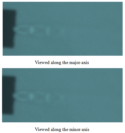 | Figure 3(b). Shadowgraph images of sonic jet at NPR 3.5 |
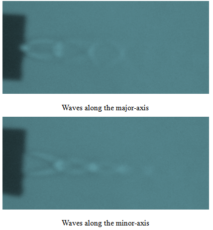 | Figure 3(c). Shadowgraph images of sonic jet at NPR 4.5 |
4. Conclusions
- In the present study, the jet propagation, issuing from circular and elliptic sonic jets operated under varied levels of underexpansion, is experimentally investigated. It was found that the reduction in sonic jet core length is strongly governed by the levels of expansion at the nozzle exit. However, the elliptical nozzle capable of shedding vortices of mixed size was found to be effective in superior mixing. The shadowgraph images confirmed the efficacy of elliptic jet compared to circular jet in mixing augmentation and weakening the shock-cell structures, which is advantageous from acoustics point of view.
ACKNOWLEDGEMENTS
- The authors acknowledge the financial support provided by Sponsored Research and Industrial Consultancy (SRIC), Indian Institute of Technology Kharagpur in order to complete the present investigation. The authors also acknowledge the High Speed Aerodynamics Laboratory at Indian Institute of Technology Kanpur, where the experiments in the present study have been conducted.
Nomenclature
- AR = Aspectratio (ratio of semi-major axis to semi-minor axis lengths)D = EquivalentdiameterNPR = Nozzle Pressure Ratio, p/p0pa = Atmospheric pressure pe= Nozzle exit pressure p0 = Settling chamber pressurep = Pitot pressure in the jet fieldX = Coordinate along the jet axis