R. J. Romero 1, A. Rodríguez Martínez 1, S. Silva Sotelo 1, J. Cerezo 2
1Engineering and Applied Science Research Centre (CIICAP), Autonomous University of Morelos State. Av. Universidad 1001, Chamilpa (62209), Cuernavaca, Morelos
2Renewable Energy Centre, Engieneering Institute (II), Baja California Autonomous University, Calle de la Normal s/n, Col. Insurgentes Este (21280), Mexicali, B.C., México
Correspondence to: R. J. Romero , Engineering and Applied Science Research Centre (CIICAP), Autonomous University of Morelos State. Av. Universidad 1001, Chamilpa (62209), Cuernavaca, Morelos.
| Email: |  |
Copyright © 2014 Scientific & Academic Publishing. All Rights Reserved.
Abstract
This paper shows a dimensionless comparison for two thermodynamic cycles. For power lower than 2 kW into each component for advanced inverse heat pumps the calculation were made. Comparison for double absorption (DAHT) and double stage (DSHT) are shown. Modelling based for a single stage absorption heat transformer (SSHT) and advanced heat transformer is detailed. Coefficient of performances are plotted as function of useful temperatures above 120ºC. DSHT and DAHT are alternative devices for operating conditions from 120 to 140°C using waste heat at 60°C. The results show the COP for DSHT and DAHT as function of waste heat temperature, ambient temperature and revalorized temperature.
Keywords:
Absorption heat transformers, Advanced heat transformer, Double stage heat transformer, Double absorption heat transformer
Cite this paper: R. J. Romero , A. Rodríguez Martínez , S. Silva Sotelo , J. Cerezo , Advanced Inverse Heat Pump Using Carrol – Water, American Journal of Environmental Engineering, Vol. 4 No. 4A, 2014, pp. 19-29. doi: 10.5923/s.ajee.201401.03.
1. Introduction
Heat recovery by heat integration analysis is an alternative for some industrial process [Feng, 2011] when heat exchange is going at similar levels. A single stage heat transformer (SSHT) is a heat pump kind made for heat revalorization. SSHT main objective is to increase the temperature from industrial waste heat or solar energy [Best, 1997; Sözen, 2007]. Several industrial process in food engineering has operating temperatures from 120 to 140°C, like sterilization of vegetables, and part of energy is delivered to surroundings at temperatures lower than 100ºC. This waste energy may recover at 60ºC or higher temperature, however, that level is no longer useful.Waste heat can be added at 60°C or 70°C into the absorption cycles for a revalorization, while the surroundings leads to the deliver heat from 20°C to 25°C. Purpose temperature is above 120°C and not higher than 140°C for sterilization vegetables process, because for higher temperatures there is undesirable effect in the vitamins concentrations [De Roeck, 2008].A heat pump (HP) is a thermal machine that transfers heat from something at a lower temperature to something at a higher temperature. There are different kinds of “heat-pumps”. Radermache et al., classificate heat pumps in type I and II. “Type I” is a device with evaporation process at lower temperature than condensation process. Type II is another device with condensation process at lower temperature than evaporation process. HP can be identified depending of operation process: compression and absorption: The compression process is performed by mechanical vapor recompression (MVR) to increase pressure and temperature of refrigerant. MVR process requires large amounts of high quality energy (electricity) which conducts the HP immediately. The absorption process is characterized by absorption of a gas in a liquid and reabsorbed in cycles. The absorption process replaces the MVR with the advantage of using low-enthalpy energy. The main disadvantage of the process of absorption is due to cyclical feature that requires a transitional period in which thermodynamic equilibrium is established throughout the system.
2. Heat Transformers
Single Stage heat transformerA single stage heat transformer (SSHT) is a device that can effectively recover about 50% of waste heat and reuse it in any manufacturing process. The characteristics of a SSHT are: (1) can increase the waste heat from a low temperature level to a higher temperature level, while consuming small amount of work done by the pumps, (2) has no large rotary devices but small pumps, (3) and this device can reduce power loss and discharge of CO2.The SSHT components are a generator, a condenser, a evaporator, an absorber, an economizer, two pumps and a expansion valve. Waste heat is added at intermediate temperature to the generator to vaporize the water from the diluted solution (low salt concentration). The vaporized water goes to the condenser where it is condensed delivering an amount of heat at low temperature, this is not useful heat, because it is at atmospheric temperature. The water leaving the condenser is pumped to the evaporator where it is evaporated by means of a quantity of waste heat at intermediate temperature. After this, the water vapour goes to the absorber where it is absorbed by the concentrated solution (high salt concentration) coming from the generator, delivering an amount of heat at higher temperature. Finally, the diluted solution returns to the generator, preheating the concentrated solution in the economizer, starting the cycle again. Figure 1 shows the SSHT cycle in a coordinated system pressure / temperature. It shows that SSHT operates at two pressure and three temperature levels where the waste heat is supplied to the generator and evaporator at intermediate temperature level. No useful heat is delivered at lower temperature in condenser. Also shows that the higher temperature is obtained in the absorber and this heat is useful for industrial process.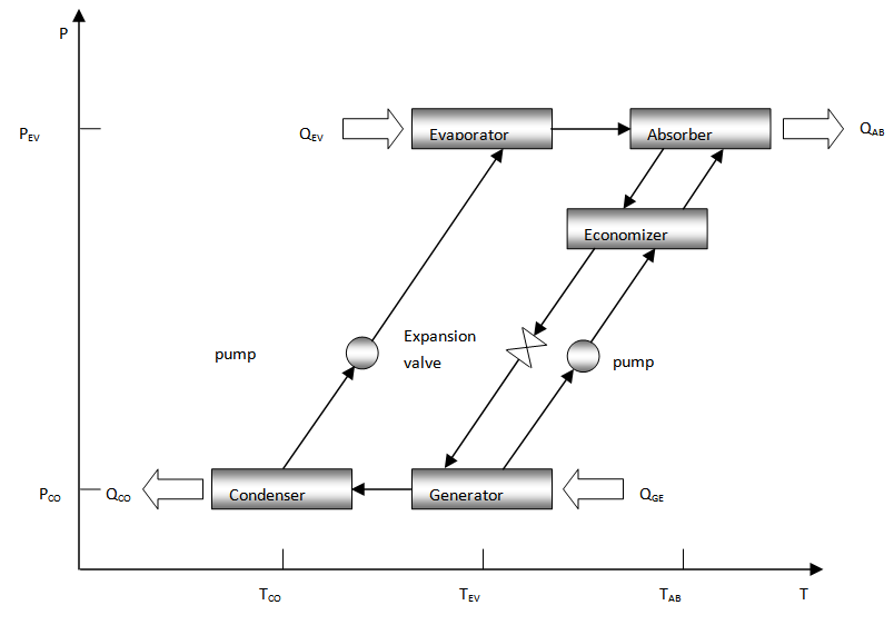 | Figure 1. Pressure – temperature schematic diagram for SSHT cycle |
2.1. Advanced Heat Transformers
A single-stage heat transformer (SSHT) can be used for industrial waste heat recovery at intermediate temperatures when it is necessary to increase the temperature similar to or lower than 50°C. However, when it is necessary to increase the temperature greater than 50°C, it could be used advanced thermal transformer such as double stage heat transformer (DSHT) and double absorption heat transformer (DAHT).
2.1.1. Double Absorption Heat Transformers
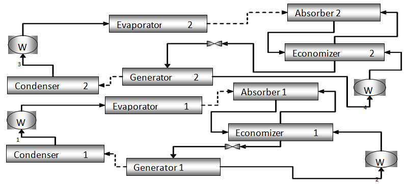
Double absorption heat transformers (DAHT) consist of a generator, a condenser, an evaporator, an absorber, a second absorber/evaporator and an economizer as shown in Figure 2. A heat source is supplied to separate the working fluid in the generator at an intermediate temperature. Then the vapourized working fluid is condensed in the condenser at a lower temperature. Then the condensed working fluid is split into two streams, one of them is pumped into the evaporator where it is vapourized at an intermediate temperature and pressure, and the other part is pumped at a higher pressure and vapourized in the second absorber/evaporator by means of an amount of available heat. The vapourized working fluid is absorbed in the absorber, at the highest temperature by the rich solution coming from the generator. The solution at an intermediate salt concentration is split into two streams, one goes to the generator preheating the rich solution through the heat exchanger and the other is fed to the absorber/evaporator absorbing the vapourized working fluid coming from the evaporator and delivering an amount of heat. Finally, the poor salt solution at a low concentration leaving the absorber/evaporator goes to the generator starting the cycle again. 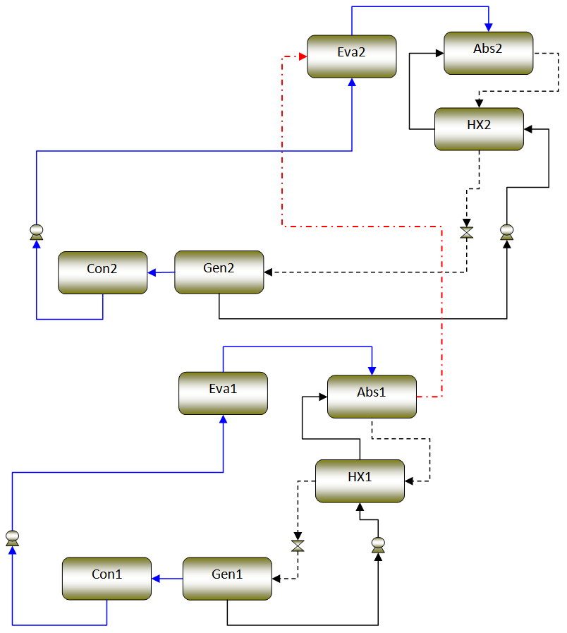 | Figure 2. Double absorption heat transformer (DAHT) |
 | Figure 3. Schematic diagram of a double absorption heat transformer |
2.1.2. Double Stage Heat Transformer
A double stage heat transformer consists of two-stage heat transformer, which can be coupled in three different ways. A double absorption heat transformer is a single-stage heat transformer, which a unit absorber / evaporator has been added.
3. Coefficient of Performance and Gross Temperature Lift
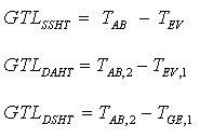
The most important design parameters for an absorption heat transformer are: the coefficient of performance, the flow ratio, the gross temperature lift and [Rosenberg, 1996]. The most important design parameters for an absorption heat transformer are: the coefficient of performance and the gross temperature lift [Rivera, 1998]. The coefficient of performance (COP) is an important parameter since this represents the efficiency of an absorption heat transformer. It is defined as the ratio of useful heat delivered and wasted heat added to the system. 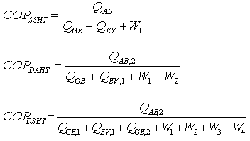 In a previous paper it was concluded that work done by centrifugal pumps were negligible because those were only 2% of waste heat. These works are not considered for COP calculation. Although the COP is less than unity always for these systems, they have the unique ability to raise the temperature of any waste heat to transform it at a useful heat [Sekar, 2011; Rivera, 2001]. COP is the fraction of recovery heat from waste heat, it is dimensionless, and therefore it may be compare several systems.The gross temperature lift (GTL) is defined as the difference between the useful temperature and the added waste heat temperature,
4. Mathematical Model
Following models developed by current authors [Rivera, 2001] the next assumptions have been made in the development of the mathematical model for the absorption heat transformers with reference to Figures 1 and 2.(i) There is thermodynamic equilibrium throughout the entire system.(ii) The analysis is made under steady-state conditions.(iii) A rectifier is unnecessary since the absorbent does not evaporate in the temperature range under consideration.(iv) The solution is saturated leaving the generator and the absorber, and the working fluid is saturated leaving the condenser and the evaporator.(v) Heat losses and pressure drops in the tubing and the components are considered negligible. The work done by the pumps is considered negligible.(vii) The flow through the valves is isenthalpic.(viii) Temperatures at the exit of the main components, the heat load in the evaporator, and the effectiveness of the economizer EFEC are all known.Following the mathematical models developed by previous papers [Romero, 2010; Best, 1997; Jun 1999] and their assumptions, comparisons were carried out. The waste heat is added at 60°C or 70°C into the evaporators and generator. The surroundings leads to the condenser to operate at 20°C or 25°C, and the purpose temperature is above 120°C and still 140°C for sterilization vegetables process, because for higher temperatures there is undesirable effect in the vitamins concentrations [De Roeck, 2008]. The useful heat obtained from DAHT and DSHT must be constant for the sterilization process because the exposed time is a critical variable [Oerlemans, 2006]. Carrol – water [Reimann, 1984] is used into the advanced system based in previous work [Huicochea, 2004; Yin, 2000] for higher COP compared with commercial mixture (aqueous lithium bromide) [McNelly, 1979]. Waste heat lead to the DAHT and DSHT to keep constant generator (TGE) and evaporator (TEV) temperatures. While absorber temperature (TAB) affect the useful heat and according equations 1 to 3, diminished also the respective COP. Economizers are pre-heater for concentrated solution from generator and it is assumed with constant effectiveness equal to 0.7 in all calculations for the comparison of both DAHT and DSHT. The effect of the effectiveness of economizer was previously reported [Kakac, 2002] and 0.7 is a value for commercial plate heat exchanger. Finally, waste heat was considered as constant value between 10 and 15 kW for this study, this waste heat is added as QEV and QGE for DAHT and QGE1, QEV1 and QEV2 for DSHT. Temperature of waste heat is considering the same for the entering into de DAHT and DSHT, of course for industrial process this mean that are large areas for heat transfer and the losses are negligible. In real process the result of this paper correspond to higher waste heat as function of heat transfer effectiveness. | (1) |
The pressures y/o temperatures in the condenser and evaporator can be known considering that he/she is water in saturation inside these components:  | (2) |
 | (3) |
Considering that it does not exist significant variations of pressure in the pipes that unite to the team, they are distinguished two areas of pressure  | (4) |
 | (5) |
It can be calculated the concentration in the generator and absorber, considering thermodynamic balance in function of the pressure in the component and their temperature:  | (6) |
 | (7) |
Since exchange of mass doesn't exist and alone of heat among the lines that are between the generator and the absorber it can be distinguished four components, with concentrations:  Since it has been considered that the absorbent doesn't evaporate
  | (8) |
Therefore alone two places exist inside the system with a well-known concentration of absorbent, generally expressed as percentage in weight:  | (9) |
Considering each state enthalpy can be evaluated in each one of the exits of the components:  | (10) |
 | (11) |
Which are evaluated using the respective equations for the mixtures used: | (12) |
Which is evaluated for saturated liquid water as: | (13) |
Considering that the vapor of water that it leaves the generator it is in saturation  | (14) |
Knowing or supposing (for design) the power given to one of the components (it may be the evaporator power) it can be calculate the flow inside the system:  | (15) |
Under the condition that accumulation of mass doesn't exist in any point of the system one has that  | (16) |
 | (17) |
And considering the relationship of flow given as  | (18) |
Making a matter balance in the absorber, it can also express in function of concentrations, as:  | (19) |
The quantity of mass that leaves the absorber toward the generator is obtained of the two previous equations and it should be positive:  | (20) |
Of the balance of mass in the absorber is the quantity of mass that leaves the generator and he/she goes toward the absorber  | (21) |
Starting from the calculated data one can know the powers in each one of the components:  | (22) |
 | (23) |
 | (24) |
With what it can be calculated the coefficient of performance as function of the revalued powers, particularly it can be re-defined without work by pumps as:  | (25) |
Termodynamic pattern of a double stage heat transformer (DSHT) it is derived of the pattern of a thermal transformer of a single stage. The heat of the absorber of the first stage is entered to the evaporator of the second stage in this study. For the pattern the following considerations are:  | (26) |
 | (27) |
 | (28) |
 | (29) |
Starting from these suppositions and knowing the temperature of condensation TCO2, the temperature of evaporation TEV2, the temperature of generation TGE2 and of absorption TAB2, we can say that: The temperature of the vapor like of the concentrated solution of exit of the generator it is the same one:  | (30) |
The pressures y/o temperatures in the condenser and evaporator can be known considering that he/she is water in saturation inside these components:  | (31) |
 | (32) |
These functions are dependent of the temperature of the saturated vapor of water. There are distinguished two areas of pressure  | (33) |
 | (34) |
Similarly to the first stage the concentrations can be calculated in the generator, and absorber for each work fluid in function of pressure and temperature:  | (35) |
 | (36) |
Since exchange of mass doesn't exist and alone of heat among the lines that are between the generator and the absorber it can be distinguished four components, with concentrations Since it has been considered that the absorbent doesn't evaporate to the operation conditions:  | (37) |
Alone two places exist inside the system with a well-known concentration of absorbent: | (38) |
Considering each state we can calculate the enthalpy in each one of the exits of the components:  | (39) |
 | (40) |
Which are evaluated using the equations of state of each work fluid:  | (41) |
Evaluated similarly (eq. 12).  | (42) |
Considering that the vapor of water that it leaves the generator it is in saturation  | (43) |
Knowing or supposing (for design) the power given in the evaporator of the second stage, similar to single stage, we calculate the flow inside the system:  | (44) |
Under the condition that accumulation of mass doesn't exist in any point of the system one has that  | (45) |
 | (46) |
And considering the relationship of flow given as  | (47) |
Making a matter balance in the absorber, it can also express as function of concentrations, as:  | (48) |
Therefore one can know the quantity of mass that leaves the absorber toward the generator  | (49) |
Therefore, by means of a balance of mass in the absorber is the quantity of mass that leaves the generator and he/she goes toward the absorber (previous exchange of heat)  | (50) |
Starting from the calculated data one can know the powers in each one of the components:  | (51) |
 | (52) |
 | (53) |
5. Results
Figure 4 and 5 shows the coefficient of performance of a DAHT and DSHT against absorber temperature, at condenser temperature of 20℃ and evaporator and generator temperature of 60℃, respectively. The coefficient of performance of the heat transformer decreases slowly from 120 to 140℃ at absorber temperature, after that COP decrease exponentially. DAHT and DSHT obtained COP values around 0.25 and 0.18 before 149℃, as can be seen DAHT has a better COP than DSHT. 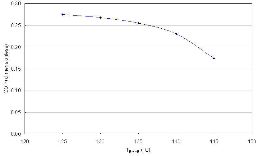 | Figure 4. COP as function of useful temperature for DAHT for TCO = 20°C and TGE = TEV = 60°C |
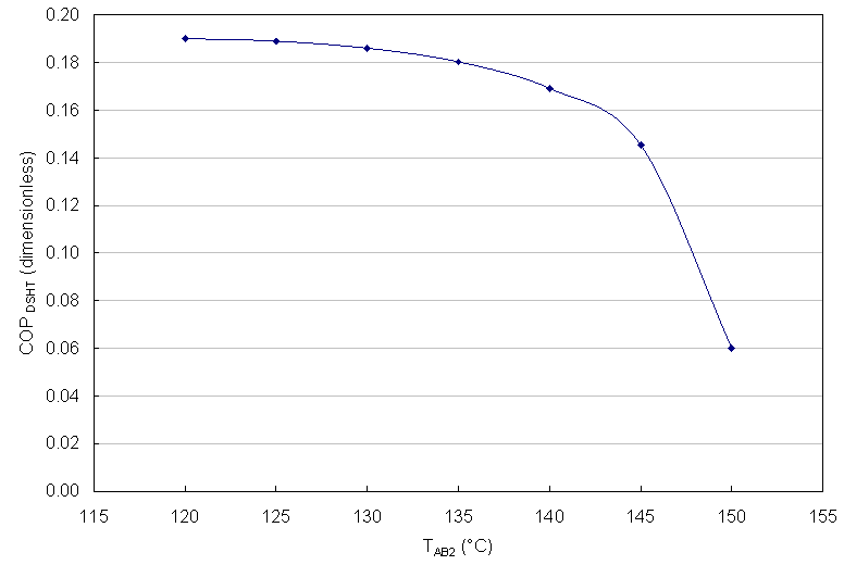 | Figure 5. COP as function of useful temperature for DSHT for TCO = 20°C and TGE = TEV = 60°C |
Figure 6 and 7 shows the coefficient of performance of a DAHT and DSHT against absorber temperature, at condenser temperature of 25℃ and evaporator and generator temperature of 60℃, respectively. The coefficient of performance of the heat transformer decreases slowly from 120 to 135℃ at absorber temperature, after that COP decrease exponentially. DAHT and DSHT obtained COP values around 0.25 and 0.18 before 149℃, as can be seen again DAHT has a better COP than DSHT, also when condenser temperature is incremented form 20 to 25℃, the working operation range is reduced too for both DAHT and DSHT. 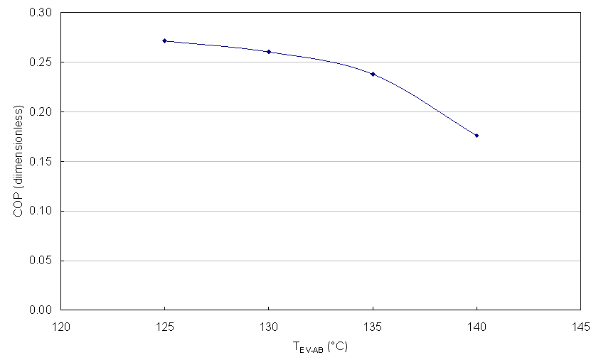 | Figure 6. COP as function of useful temperature for DAHT for TCO = 25°C and TGE = TEV = 60°C |
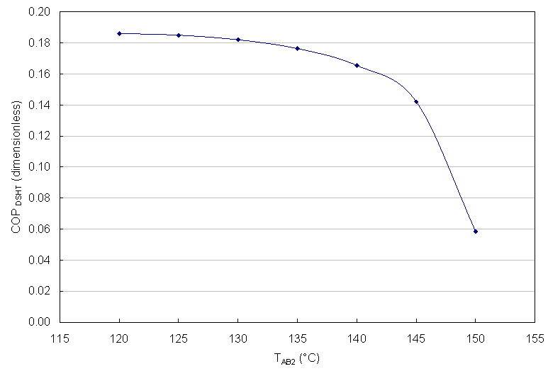 | Figure 7. COP as function of useful temperature for DSHT for TCO = 25°C and TGE = TEV = 60°C |
Figure 8 and 9 shows the coefficient of performance of a DAHT and DSHT against absorber temperature, at condenser temperature of 25℃ and evaporator and generator temperature of 70 C, respectively. The coefficient of performance of the heat transformer decreases slowly from 120 to 135℃ at absorber temperature, after that COP decrease exponentially. DAHT and DSHT obtained COP values from 0.26 to 0.24 and from 0.13 to 0.12 before 135℃, respectively. DSHT was affected significativelly when condenser temperature increase from 20 to 25℃ see figure 6 and 10.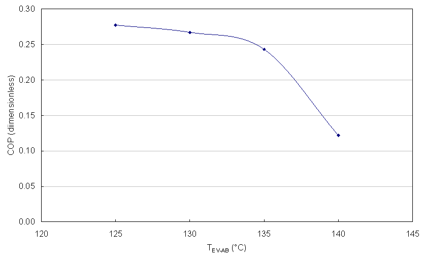 | Figure 8. COP as function of useful temperature for DAHT for TCO = 25°C and TGE = TEV = 70°C |
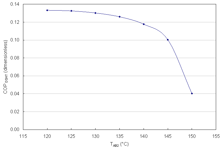 | Figure 9. COP as function of useful temperature for DSHT for TCO = 25°C and TGE = TEV = 70°C |
Figure 10 show thermal capacity for each component and coefficient of performance versus absorber temperature for a DAHT at surroundings temperature of 20ºC and waste heat at 70ºC. It can be seen that the tendency decrease when absorber temperature decrease. COP diminish from 0.28 to 0.17, that means a reduction from original energy to the process if total energy is recycled to the heat source. This recycled energy reduces in same fraction the gas emissions 17% at higher useful temperature (140ºC) and 28 % reduction at 125ºC.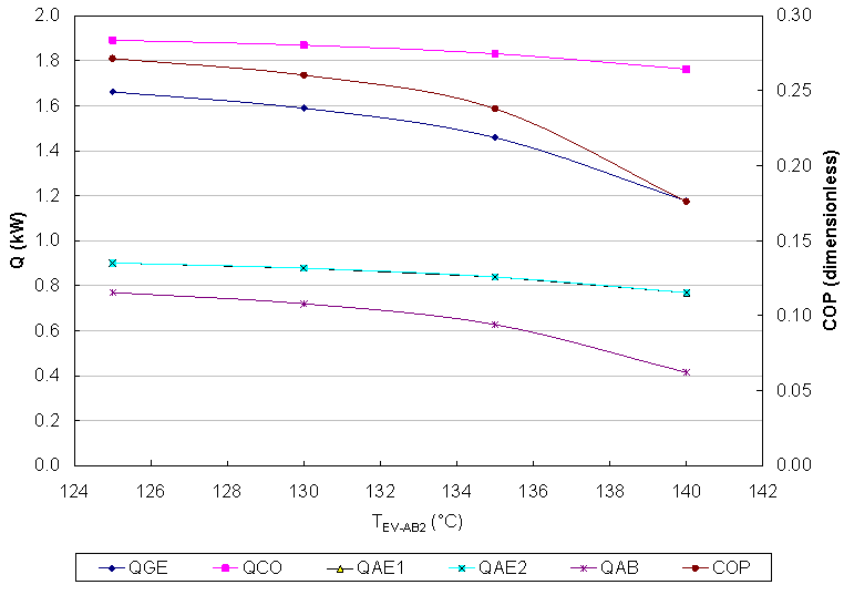 | Figure 10. Power for components into DAHT and COP for Figure 3 conditions |
6. Conclusions
Single stage heat transformer (SSHT) has crystallization limit, therefore advanced heat transformer are proposed devices for waste energy recovery at higher levels than SSHT. For food industrial process the double absorption heat transformer (DAHT) and double stage heat transformer (DSHT) were calculate for recycle heat at temperatures from 120°C to 140°C, considering sterilization vegetables process. The results shows that it is possible to recover energy from 70°C for some surroundings conditions, with a Coefficient of performance (COP), in DAHT from 0.147 to 0.198. Than means between 14 to 19 % of energy recovery from waste heat at 70°C. The other analyzed advanced system was a DSHT, with a first stage useful temperature from 95ºC to 100°C, in those cases, the COP is higher than DAHT at 120°C, and 140°C. The COP for 140°C goes from 0.277 to 0.289. It is 27 % to 28% energy recovery from waste heat at 70°C and recycled to 140°C. Finally, the comparison of both advanced cycles indicates that surroundings temperature affect the performance of system. The higher condensation temperature into de DAHT and DSHT diminish the COP values, both systems recovers higher amount of energy at 20°C instead 25°C.
ACKNOWLEDGEMENTS
Authors thanks to the 167434 Basic Science project and the “Red de Fuentes de Energía” founded by CONACyT.
References
| [1] | Best, R., Rivera W., Cardoso M.J., Romero R.J., Holland F.A., (1997), Modeling of single stage and advance absorption heat transformers operating with the water/carrol mixture, Applied Thermal Engineering, Vol. No. 11, pp. 1111-1122. |
| [2] | De Roeck A., Sila D. N., Duvetter T., Loey A. V., Hendrickx M., (2008), Effect of high pressure/high temperature processing on cell wall pectic substances in relation to firmness of carrot tissue, Food Chemistry, Vol. 107, pp 1225–1235. |
| [3] | Feng X., Pu J., Yang J., Chu K.H., (2011), Energy recovery in petrochemical complexes through heat integration retrofit analysis, Applied Energy, Vol. 88, pp 1965–1982. |
| [4] | Sekar, S., Saravanan, R., (2011), Experimental studies on absorption heat transformer coupled distillation system, Desalination, 274 (1-3), pp. 292-301. |
| [5] | Huicochea A., Siqueiros J., Romero R. J., (2004), Portable water purification system integrated to a heat transformer, Desalination, Vol. 165, pp 385-391. |
| [6] | Jun J., Masaru I., (1999), Behavior of a two-stage absorption heat transformer combining latent and sensible heat exchange modes, Applied Thermal Energy, Vol. 62, pp 267-281. |
| [7] | McNelly I. A., (1979), Thermodynamic properties of aqueous solutions of lithium bromide, ASHRAE Transactions, pp. 413-434. |
| [8] | Oerlemans K., Barrett D. M., Bosch S. C., Verkerk R., Dekker M., (2006), Thermal degradation of glucosinolates in red cabbage, Food Chemistry, Vol. 95, pp 19–29. |
| [9] | Reimann R. and Biermann W. J., (1984), Development of a single family absorption chiller for use in solar heating and cooling system, Phase III Final Report, Prepared for the U. S. Department of Energy under contract EG-77-C-03-1587, Carrier Corporation. |
| [10] | Rivera W., Cardoso M.J., Romero R.J., (2001), Single-stage and advanced absorption heat transformers operating with lithium bromide mixtures used to increase solar pond’s temperature, Solar Energy Materials & Solar Cells, Vol. 70, pp 321-333. |
| [11] | Rivera W., Romero R.J., (1998), Thermodynamic design data for absorption heat transformers. Part 7. Operating on an aqueous hydroxide, Applied thermal Engineering, Vol. 18, pp. 147-156. |
| [12] | Romero R.J., Silva Sotelo S., Cerezo J., (2010), First Double Stage Heat Transformer (Dsht) in Latinamerica, Chemical Engineering Transaction, Vol. 9, pp 149 – 155. |
| [13] | Sözen A., Serdar Y. H., (2007), Performance improvement of absorption heat transformer, Renewable Energy, Vol. 32, pp 267-284. |
| [14] | Yin J., Shin L., Zhu M. S., Han L. Z., (2000), Performance analysis of an absorption heat transformer with different working fluid combinations, Applied Energy, Vol. 67, pp 281-292. |


 In a previous paper it was concluded that work done by centrifugal pumps were negligible because those were only 2% of waste heat. These works are not considered for COP calculation. Although the COP is less than unity always for these systems, they have the unique ability to raise the temperature of any waste heat to transform it at a useful heat [Sekar, 2011; Rivera, 2001]. COP is the fraction of recovery heat from waste heat, it is dimensionless, and therefore it may be compare several systems.The gross temperature lift (GTL) is defined as the difference between the useful temperature and the added waste heat temperature,


 Since it has been considered that the absorbent doesn't evaporate


 Abstract
 Reference
 Full-Text PDF
 Full-text HTML