R. J. Romero , S. A. Serna Barquera , A. Rodríguez Martínez , S. Silva Sotelo , M. A. Cruz Chavez , M. A. Basurto Pensado , J. C. García , J. A. Rodríguez
Engineering and Applied Sciences Research Centre, Autonomous University Morelos State, Morelos 62209, Mexico
Correspondence to: R. J. Romero , Engineering and Applied Sciences Research Centre, Autonomous University Morelos State, Morelos 62209, Mexico.
| Email: |  |
Copyright © 2014 Scientific & Academic Publishing. All Rights Reserved.
Abstract
In the following article the joining of a system of electric generation is described with a thermal transformer by absorption (AHT). The electric system is formed by to cell of combustible type PEM in which is entered hydrogen and oxygen to pressures of the same order of magnitude. The heat that is necessary to release of the cell of fuel is given an AHT using the mixture aqueous lithium bromide. The mixture H2O / LiBr has been selected by its smaller operation generation temperatures to 373 K. The results show the operation coefficient and the cogeneration coefficient in function of the temperature of operation of the cell of fuel (TFC) and the temperature of the surroundings (Tamb). The results show the obtaining of revalorized useful heat and electric power.
Keywords:
Absorption heat transformer, Fuel cell, Efficiency of cogeneration, Coefficient of performance
Cite this paper: R. J. Romero , S. A. Serna Barquera , A. Rodríguez Martínez , S. Silva Sotelo , M. A. Cruz Chavez , M. A. Basurto Pensado , J. C. García , J. A. Rodríguez , Waste Heat Revalorization with Electric Generation Based on Fuel Cell, American Journal of Environmental Engineering, Vol. 4 No. 4A, 2014, pp. 11-18. doi: 10.5923/s.ajee.201401.02.
1. Introduction
The cells of fuels are a technology that allows transforming the chemical energy by means of a reaction of “hidrogenesis” to energy that can recover in electric form by means of electrodes and another part as thermal energy for half a circuit of recirculation of a fluid “heatconducter”. The cells of fuels have different ranges of operation temperature (TFC). The TFC to which useful heat is exchanged for the systems of absorption depends on the type of cell of fuel [Jiao, 2010]. On the other hand, the systems of absorption used in way of thermal transformer AHT have been used to revalorize the temperature of heats of industrial waste. A recent application of these systems has been the purification of water [Romero, 2008, Ibarra – Bahena, 2013]. The use of several technologies for the efficient use of the energy has promoted the cogeneration or tri generation, in the case of the AHT with PEMFC was considered the integration of the energy revalued to the same process of where it comes, however, the purification of water allows an increment in the COP of the AHT for the internal recirculation [Romero, 2008].
2. PEMFC and AHT
The fuel cells transform the chemical energy in thermal energy. Their energy balance can present in the following way: The fuel cells that use membranes cannot operate to high temperatures [Li, 2006] for what their operation and efficiency depend from inferior temperatures to 373 K and typically up to 353 K, obtaining the biggest efficiency to 333 K for the humectation of the membrane. The operation temperature also limits the generation of water, together with the pressure. The increase of temperature and the decrease of pressure reduce the hidrogenesis [Larminie, 2003].
3. Modeling of the PEM Fuel Cell
The quantity of electric power that can be extracted of a cell type PEM has a broadly modeling and that it depends mainly on two parameters: pressure of gases and operation temperature [Zhang, 2006] according to the following model: 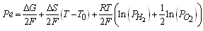 | (Eq.1) |
With this model and supposing T0 under standard conditions from laboratory to 298 K, the evaluation of the potential with constant current suggests a minimum decrease of the cell, considering that the relationship among the pressure of hydrogen on the oxygen pressure is not bigger than 3. It is advisable according to the experimentation found in literature [Bernardi, 1992] to not exceed this relationship of pressures to keep a “drag” that allows the operation of the cell. The thermodynamic values have been taken of literature [Sonntag, 2008; Wark, 1998]. The variation of the maximum total energy (Q + Pe) given by the cell it is in function of the temperature TFC like it is shown in the figure 2. In that figure it can be observed that the variation of the total energy behaves in a lineal way and with smaller values to 0.4%. 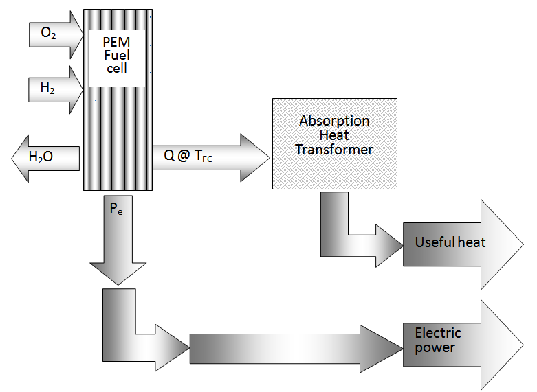 | Figure 1. Schematic diagram of a PEM |
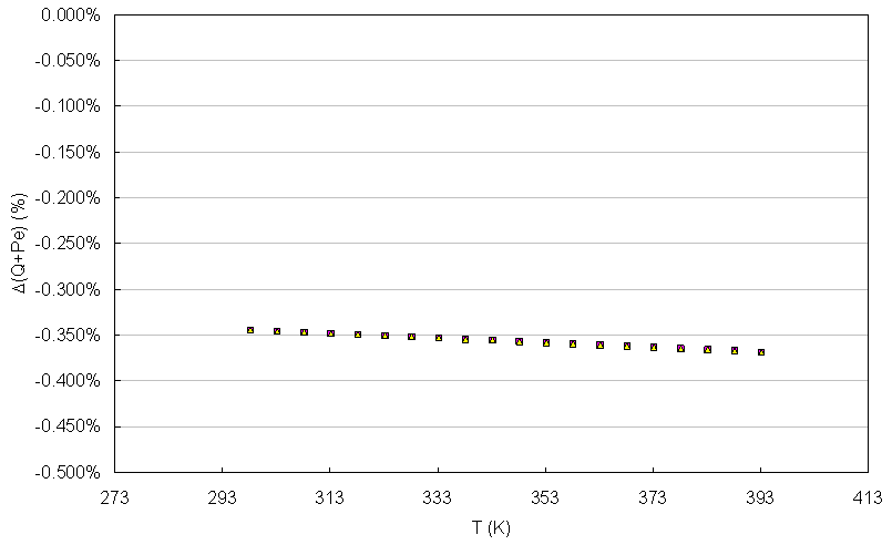 | Figure 2. Variation of the total energy of the cell in function of the temperature |
With base to the proposed pattern, the thermodynamic efficiency has been calculated in function of the temperature under the reported following pattern:  | (Eq.2) |
Where ΔG is the energy free of Gibbs that corresponds to the maximum work carried out by the reaction happened in the PEM to constant conditions of pressure and temperature, ΔH it is the enthalpy change due to the masses reactants of hydrogen, to the temperature T and ΔS are the total change of entropy in the reaction. According to reports this thermal efficiency can be until of 83% at 298 K. In the case of a cell type PEM for 5 kW approximately, of operation, we use the calculation from reported data to correlate the efficiency in function of the temperature and the pressures of the gases [Kazim, 2004]. With the proposed pattern we observe that the differences ΔH and ΔS are increased proportionally with the temperature, for what is expected that it is smaller than the unit and diminish with regard to the increase of the temperature. The values of the figure 3 correspond reasonably those reported in the literature that defines the efficiency of cells in those that the heat is extracted for a useful use [Haynes, 2001].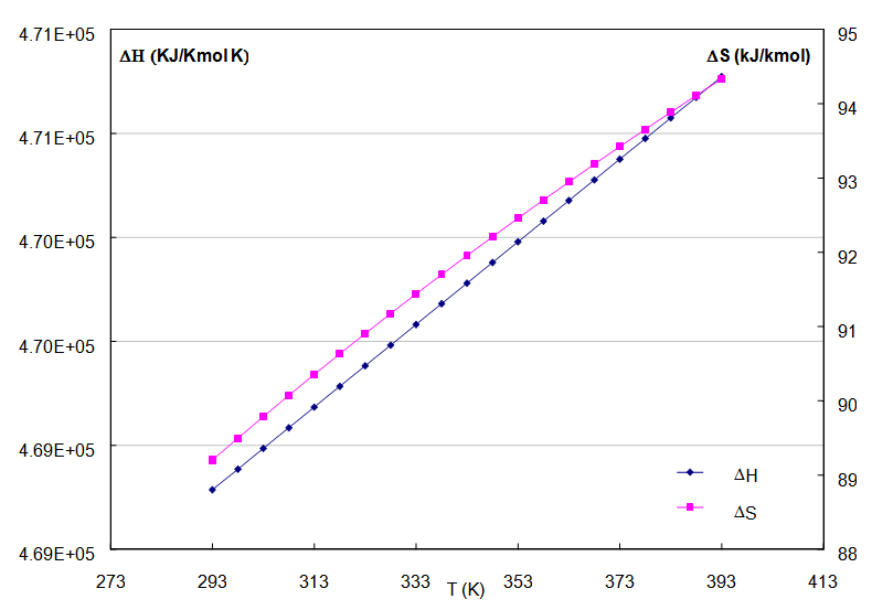 | Figure 3. Enthalpy and entropy changes as function of the temperature for the PEMFC |
4. Calculation of the Electric Power and the Thermal Energy
The electric potential in a PEMFC stays practically constant between 293 and 333 K, however for further values to 353K and close to 393K the potential diminishes [Zhang, 2006]. On the other hand the current density increases proportionally with regard to the temperature, for what the biggest quantity in electric power that it can transform for the electrodes happens to 353 K. These good values of Pe will correspond reasonably to the literature pattern that proposes the use of nafion 112 and nafion 117, based on the load density and extrapolated to a electric power of 5 kW, like it is shown in the figure 4. In this figure, the theoretical electric power has been calculated as product of two functions of temperature: the density of current of a constant area and the potential measured in nafion PEM. The resulting function is valid for temperatures of 296 K and until 393 K and a relationship of pressures similar to 1.  | (Eq.3) |
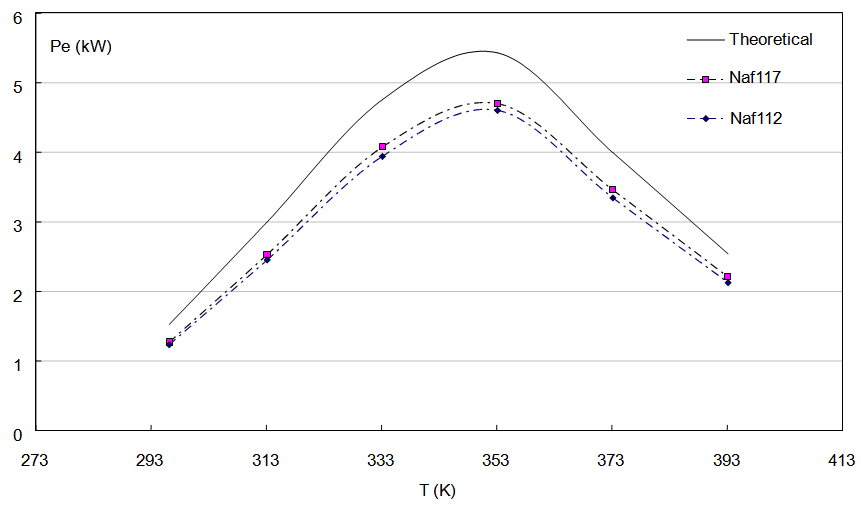 | Figure 4. Theoretical power for a PEMFC and powers calculated for membranes of Nafion 117 and Nafion 112 |
In the figure 5 the values of the thermodynamic efficiency (η) are presented, the thermal energy according to the pattern proposed by literature [Pilatowsky, 2011] and that is smaller than 43% compared with the calculated with the Eq. 2. The relationship among the thermal power with regard to the electric power is on the average 0.76, that is to say the electric power is bigger 24% that the extracted thermal power of the cell [Kazim, 2004]. 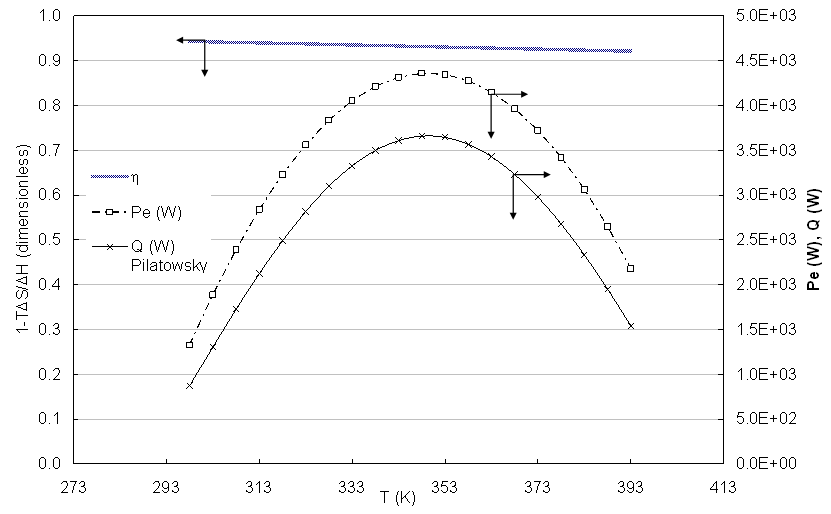 | Figure 5. Thermodynamic efficiency and electric and thermal powers calculated in function of the temperature |
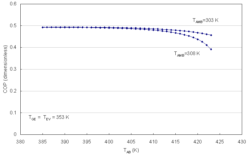
Figures 6 to 9 show the Coefficient of Operation of an AHT, operating with the mixture aqueous lithium bromide, as function of the temperature of the surroundings (Tamb) and the temperature of the cell TFC.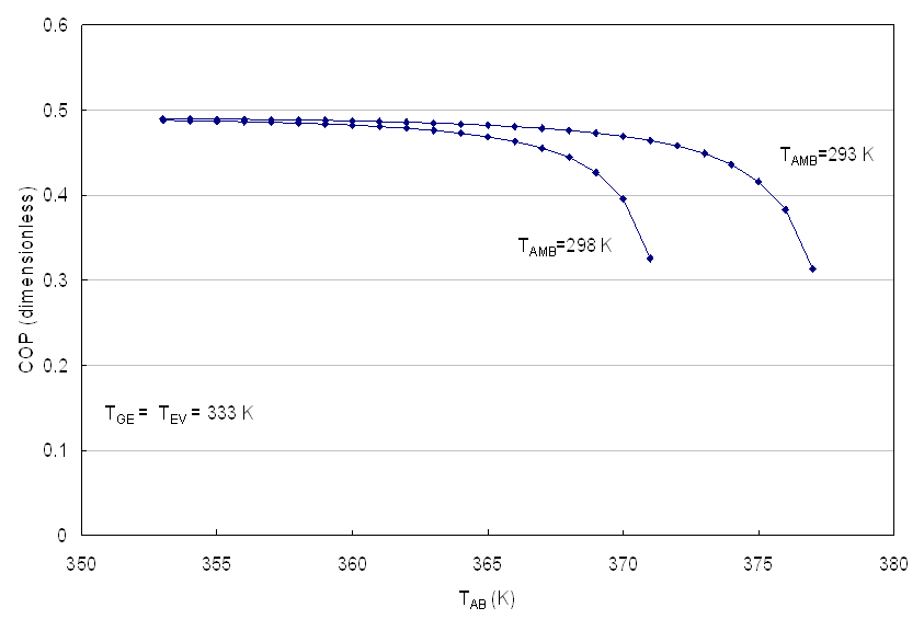 | Figure 6. COP as function of the TAB for TFC > 333 K |
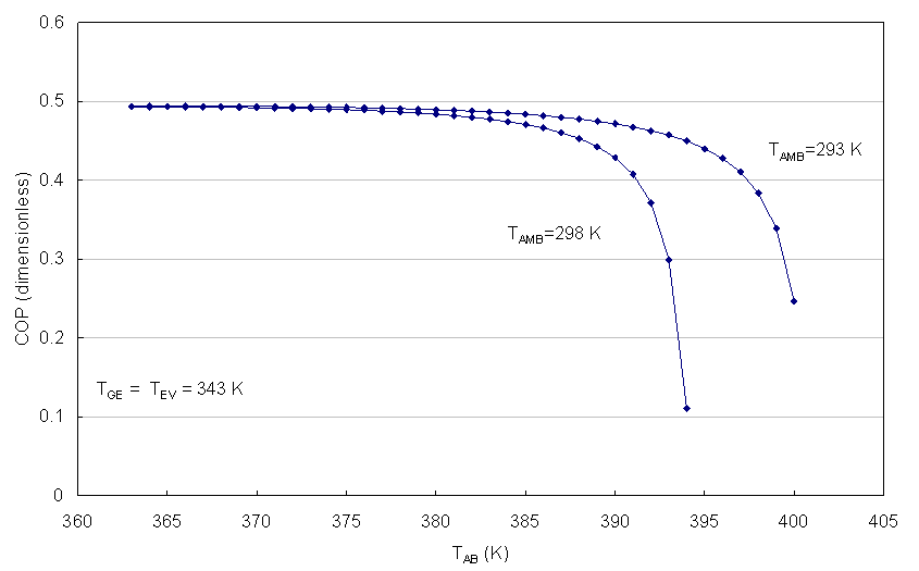 | Figure 7. COP as function of TAB for TFC > 343 K |
 | Figure 8. COP as function of TAB for TFC > 353K |
 | Figure 9. COP as function of TAB for TFC > 363 K |
5. Calculation of the Cogeneration Efficiency
Defining the efficiency of cogeneration (EOC) as the electric power relationship (Pe) that is extracted of the cell and the useful heat of the absorber of the AHT with regard to the total energy liberated in the cell: 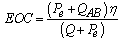 | (Eq.4) |
The temperature of the PEM leads to the values η that were shown in the figure 5 and considering an increment of the temperature (GTL) of 30 K, that is assumed that a part of the heat given by the cell is increased 30 K and it is useful for some application, the EOC it is obtained as function of the temperature of the PEM like it is shown in the figure 10. In this figure the energy relationship is also shown for the same temperature of the cell PEM and the biggest thermal energy; it is noted than at 350 K practically with a relationship of 0.84. However, the EOC has its bigger value (0.7166) to 343 K, that is to say, although one can have a cogeneration from 333 K and up to 363 K, the electric sum of energy and recovery of heat has a maximum value. 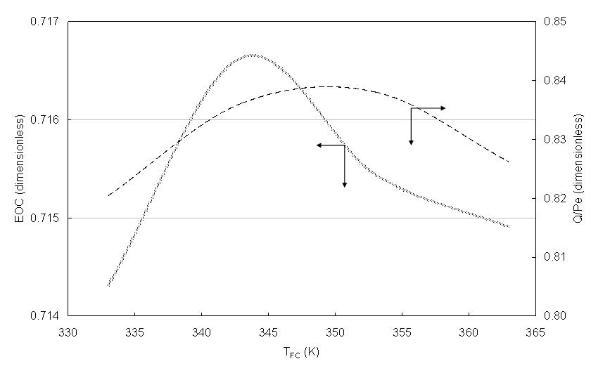 | Figure 10. EOC and thermal fraction as function of the fuel cell temperature |
6. Conclusions
In this article the cogeneration has been presented based on a type PEM fuel cell. The thermodynamic pattern that has been used with reported data to correlate the useful thermal energy of the cell PEM as function of its operation temperature. The thermodynamic efficiency that has been calculated coincides with values reported in the literature. The calculated efficiency was used to determine the quantity of thermal energy with reference to the pattern presented by literature. The calculated power was used in an absorption heat transformer using the aqueous lithium bromide for revalorize waste heat. The cogeneration coefficient (EOC) it has been re-defined for this joining. The values of EOC are near at 0.72 and they show the biggest energy transformation to 343 K.
ACKNOWLEDGEMENTS
To the Project of Basic Science 167434 and to the Thematic Net of Sources of Energy, of the CONACyT.
References
| [1] | Bernardi DM, Verbrugge MW. To mathematical model of the solid-polymer-electrolyte fuel cell. J Electrochem Soc 1992; 140: 2767–72. |
| [2] | Haynes C., Journal of Power Sources, Vol. 92, 2001. |
| [3] | Ibarra – Bahena, et al., Experimental Thermal and Fluid Science, Vol. 51, 2013. |
| [4] | Jiao K. & Li X, Water transport in polymer electrolyte membrane fuel cells, Progress in Energy and Combustión Science, Press. Art., 2010. |
| [5] | Kazim A., Energy Coversion and Management, Vol. 45, 2004. |
| [6] | Larminie J, Dicks A. Fuel cell systems explained. Chichester: John Wiley & Sons; 2003. |
| [7] | Li X. Principles of fuel cells. New York: Taylor & Francis; 2006. |
| [8] | Pilatowsky I. et. al, Cogeneration Fuel Cell – Sorption air conditioning systems, Springer, 2001. |
| [9] | Richard E. Sonntag, Claus Borgnakke and Gordon J. Wylen goes, Fundamentals of Thermodynamics, Sixth Edition, Wiley & Sons, 2003. |
| [10] | Romero R.J. & Rodríguez A., Desalination Vol. 220, 2008. |
| [11] | Wark Kenneth, Thermodynamics, 5th edition, McGraw Hill, 1998. |
| [12] | Zhang J. et to the., Journal of Power Sources, Vol. 163, 2006. |
 Abstract
 Reference
 Full-Text PDF
 Full-text HTML