-
Paper Information
- Next Paper
- Previous Paper
- Paper Submission
-
Journal Information
- About This Journal
- Editorial Board
- Current Issue
- Archive
- Author Guidelines
- Contact Us
American Journal of Condensed Matter Physics
p-ISSN: 2163-1115 e-ISSN: 2163-1123
2014; 4(3A): 1-7
doi:10.5923/s.ajcmp.201401.01
Low Temperature Microplasma Jet at Atmospheric Pressure for Inducing Surface Modification on Polyethylene Substrates
 Abstract
 Reference
 Full-Text PDF
 Full-text HTML
E. C. B. B. Aragão1, J. C. Nascimento1, A. D. Fernandes1, F. T. F. Barbosa1, D. C. Sousa1, C. Oliveira1, 2, G. J. P. Abreu1, V. W. Ribas1, B. N. Sismanoglu1
1Technological Institute of Aeronautics (ITA), Physics Department, São José dos Campos, Brazil
2Laboratório Nacional de Ciência e Tecnologia do Bioetanol–CTBE/CNPEM, Campinas, Brazil
Correspondence to: B. N. Sismanoglu, Technological Institute of Aeronautics (ITA), Physics Department, São José dos Campos, Brazil.
| Email: |  |
Copyright © 2014 Scientific & Academic Publishing. All Rights Reserved.
An atmospheric pressure ac microplasma jet device with Cu spiral-torsion-spring type electrodes was developed. This electrode geometryenables the generation of low power and stable micro plasma jet operated in Ar, He, O2, N2 and air at flux rates ranging from 2 to 12 L/min, applying an ac high voltage at 60Hz frequency. Moreover, the device is absent of dielectric parts which prevents contamination of the plasma. To observe the outflow pattern a Schlieren photography system was used, resulting in broaden and continuous laminar gas flow. Optical emission spectroscopy measurements allow us to infer the mean gas temperature of plasma jet from the outer electrode along its axial position. A temperature decrease of 110℃ to 40℃ was observed up to 5 mm and beyond this gas temperature the plasma jet reaches room temperature, so enabling it to use in treatment of heat-sensitive surfaces such as biomaterials and polymers like polyethylene.
Keywords: Microplasma jet, Schlieren photography, Gas temperature, Optical emission spectroscopy, Polyethylene
Cite this paper: E. C. B. B. Aragão, J. C. Nascimento, A. D. Fernandes, F. T. F. Barbosa, D. C. Sousa, C. Oliveira, G. J. P. Abreu, V. W. Ribas, B. N. Sismanoglu, Low Temperature Microplasma Jet at Atmospheric Pressure for Inducing Surface Modification on Polyethylene Substrates, American Journal of Condensed Matter Physics, Vol. 4 No. 3A, 2014, pp. 1-7. doi: 10.5923/s.ajcmp.201401.01.
1. Introduction
- Atmospheric Pressure Microplasma Jet (APMJ) can be generated through a number of configurations, generally using noble gases [1-14]. The APMJ are suitable for industrial and research applications, such as surface modification, biological material sterilization, biomedical applications (dermatological, dental, etc.), ozone formation and treatment of heat-sensitive materials [8]. In general, APMJ is produced between planar or tube-type shape electrodes and the gas flow expulses the plasma into the ambient air, strongly reducing the gas temperature (much lower than the electron temperature) allowing several other applications [8]. McKenna et al. [15] used two different atmospheric pressure microplasma systems for surface engineering of a range of nanomaterials. Specifically a gas-phase approach from vaporized tetramethylsilane has been used to synthesize silicon carbide nanoparticles with diameters below 10 nm. Microplasma-liquid system has been used to tailor surface properties of silicon nanoparticles and to reduce graphene oxide into graphene. Gregório et al. [16] presents an imaging analysis of stable microplasmas produced in air, argon, and helium at atmospheric pressure, using a continuous microwave (2.45-GHz) excitation. The microplasma develops within the 50–200μm gap created between two metal electrodes (6 mm in length), placed at the open end of the transmission line. Zhu et al. [17] used a direct current, non-thermal atmospheric-pressure microplasma with He/O2 gas mixture to characterize the electrical properties as a function of the oxygen concentration. They observed a self-pulsed mode (negative resistivity) before the transition of the discharge to normal glow mode. Optical emission spectroscopy (OES) was used from both end-on and side-on along the plasma to analyze the reactive species generated in the plasma, which allows for enhanced applications in health and medical related areas. Hong et al. [18] presents an atmospheric-pressure N2-plasma jet generated from microdischarges in a porous dielectric. A plasma jet with a length of 42 mm was produced by feeding nitrogen gas through a porous alumina installed between an outer electrode and a hollow inner electrode and by applying 60 Hz sinusoidal voltage wave to the electrodes. Microdischarges in the porous alumina are ejected as a plasma jet from the outer electrode through a 1 mm hole by increasing the applied voltage, showing that the temperature of the jet decreases to a value close to room temperature. Benedikt et al. [19] developed an RF microplasma jet working at atmospheric pressure for thin film deposition. One capillary tube was excited by an RF frequency of 13.56MHz at rms voltages of around 200–250V. The plasma was generated in a plasma forming gas (He or Ar) in the annular space between the capillary and the ceramic tube. The electron number densities were around 8×10²⁰m−3, measured using optical emission spectroscopy. The gas temperature Tg stays below 400K. Deposition of hydrogenated amorphous carbon films and silicon oxide films has been tested using Ar/C2H2 and Ar/ hexamethyldisiloxane/ O2 mixtures, respectively. Mohamed et al. [20] performed microplasma where the electrode’s opening was about 200 μm diameter. They measured Tg by evaluating the rotational (0 - 0) band of the second positive system of N2. Sismanoglu et al. [3, 4] and Gomes et al. [5] studied electrical parameters of relatively high pressure microplasmas, showing the different modes of operation, the pre-breakdown and breakdown behaviors and the main gas parameters. For pressures ranking from 90 to 800 Torr of Ar flow at 0.03 l.min-1 and currents from 5 to 20 mA, OES measurements results electron number density ne∼1014 cm-3, Tg∼650 K and excitation temperature Texc∼8000 K. By flowing gas at 0.7 l.min-1, microhollow cathode-type microplasma yields for ne (2 - 41014 cm-3), Tg (460 - 640 K), Texc (∼7000 K), when the discharge current (Id) ranges from 7 to 15 mA [3]. The alternating current (ac) operating APMJ produced in the past few years presents characteristics of cold plasma and are suitable for various applications [9, 10, 13, 14]. Nevertheless, the nozzle cross-sectional area has diameter less than 1 mm because generally is used a micro perforated hole in plane electrode foils through which the gas is flowing. In the majority of these devices, the feed gas was nitrogen and the plasma is generated applying an ac high voltage of high frequency. Hong et al. [9] developed ac APMJ operated at 20kHz in microhollow cathode discharge with hole of 500µm diameter, suitable for N2 gas. Long plasma jets of up to 6.5 cm operated at 6.3 L/min and gas velocity of 535m/s were reported. Giuliani et al. [13] used the same configuration, but with hole diameter of 1mm, operated at 60Hz and with flow rate of about 10L/min (power of 5 – 13kV) of air. Recently, Hong et al. [14] modified this device, incorporating porous alumina at the exit nozzle, but maintaining 1mm in hole diameter of the tubular electrode. They used nitrogen as the working gas. Kim et al. [10] produced ac APMJ operated at 20kHz with N2 as feed gas. The anode was made with eightmicro holes, each with diameter of 200µm and the input voltages was ranging from 5.5 to 9.5kV. Hong et al. [21] fabricated also an ac APMJ device operating at 20kHz with N2 gas and diameter of the hole in the outer electrode -700µm. In this work, APMJ device was easily fabricated in a pencil-type device to produce stable cold plasma suitable for applications and research in a low manufacturing cost. The main difference of this device in comparison with the previously cited is the ability to operate with molecular and atomic (noble) gases, including compressed air, at lower power consumption, lower gas flow, low frequency and good stability. This is possible due the electrode geometry that has a spiral-torsion-spring shape with diameter of 2.5 mm that allows broadening of the microplasma jet at the exit hole. Polyethylene organic substrates have been used to investigate the surface modification applying APMJ. The surface modification was observed through Water Contact Angle (WCA) measurements.
2. Experimental
- One can see in Fig. 1 the schematic of the experimental set-up where the two spring spiral torsion-type Cu electrodes are separated each other by 1mm. The spiral electrode is wound flat, with rectangular section material (width b = 1.5mm, and thickness t = 30µm) with constant space between the coils, through which the gas is flowing. The electrodes are arranged parallel and are inserted in a quartz tube (the tube can be substituted by glass) with 2.6mm inner diameter (the nozzle cross-sectional area) and the inter electrode distance is about 1.2mm. Generally, dielectric is used to fill this gap in dc or ac micro plasmas, but our micro jet is free from dielectric taking advantage on its fabrication and, in addition, preventing from contamination of the plasma with sputtered materials. The ac power supply used in this work is transformer for neon light operated at 60Hz (20kV, 40mA), coupled with a variable autotransformer in order to avoid excessive current and to allow voltage control.
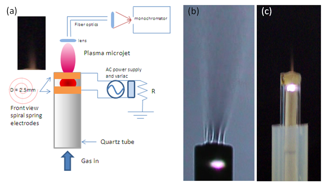 | Figure 1. (a) Schematic representation of the microplasma jet generated by spiral-torsion-spring electrodes and the schematic representation of the electrical circuit (the inset represents the photograph of air plasma jet). (b) Schlieren image of the plasma laminar outflow and (c) Picture showing the N2 microplasma jet and the bright glow discharge between electrodes |
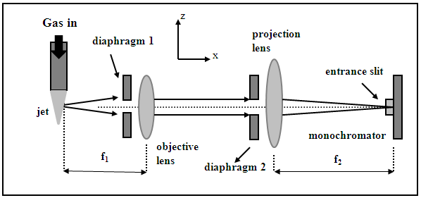 | Figure 2. Experimental set-up of spatially resolved optical emission spectroscopy |
 , where L is the entrance slit opening. To select a plasma volume for scanning, one should only move the projection lens in the z direction (Fig. 2). A Princeton monochromator with focal length f = 0.5 m, equipped with a set of holographic diffraction gratings and a CCD camera was used to obtain spectra in real time in the case of the determination of the electron excitation temperature.
3. Results and Discussion
- The inset in Fig. 1a represents the photograph of air plasma jet. Fig. 1b and 1c shows the Schlieren image of the plasma laminar outflow and a picture of the N2 microplasma jet system, respectively. As can be seen in Fig. 1b, the gas flow travels through the internal channels of the two electric spiral-type electrodes (diameter D = 2.5mm) forming a series of thin streams which begins to unite from the tip of the outer electrode, thus resulting in broaden and continuous laminar gas flow. The jet has a visible radial diameter of approximately 1.5 mm with afterglow surrounding the jet, as can be seen in Schlieren photography. Cylindrical shape plasma with high brightness is generated between the two electrodes (see Fig. 2c) and the intense gas flow drags this plasma to the external environment, forming a distended plasma plume. Once at the external environment, the mixture of the gas with the atmospheric air occurs, which significantly reduces the temperature of the plasma (afterglow). The jet elongates axially when the flow rate is increased, from 2 to 12L/min, maintaining the laminar behavior. Electrical measurements were performed with a digital oscilloscope (Tektronix) with a high voltage and current probe (1000x). The gas temperature was measured by both a K-type thermocouple and optically. The emitted radiation by the microplasma was guided by optical fiber via entrance slit onto a Princeton monochromator (or onto the Jobin-Yvon monochromator)with focal length f = 0.5 m, equipped with a set of holographic diffraction gratings and a CCD camera (see Fig.1a). Optical emission spectroscopy (OES) measurements were carried out in order to obtain mainly information about the excited species of the plasma [6, 7]. The voltage-current characteristic curves were found to be typical for ac glow discharges, showing voltage and current waveforms of the discharge, where the pre-breakdown phase of the input voltage of the power source has sine waveform (f = 60Hz). When increasing the voltage one distortion of the voltage waveform and the discharge voltage is observed, composed of a number of pulses with amplitudes in the range (0.1 – 4kVsawtooth wave profile) for Vrms=1.2kV and Im = 160mA (for N2 gas flow rate of 8L/min). For individual mixtures between O2, N2 and air with 1%Ar and for pure He and Arworking gas, the intense lines of Ar I 4p – 4s and 5p – 4s transitions (706.7, 738.4, 763.5, 800.6, 810.4, 416.4, 419.1, 420.1 nm) and He emission spectrum (447.2, 501.6, 587.6, 776.8, 706.5 nm) have been observed. Boltzmann-plotmethod (BP) [6, 7] was performed with these lines to estimate the plasma electron excitation temperature (Texc). The results are: for molecular gases with 1%Ar, Texc = 0.64eV, for pure He, Texc = 0.51eV and for Ar, TAr = 0.60eV. The gas temperature (Tg) appears to be an important factor when direct medical application is envisaged e.g. for treatment of different skin diseases like mycoses or other common fungal infection. As it has be seen later, temperature about 40℃ of the plasma plume together with high electron oscillation energy and densities, turn this APMJ highly suitable for express treatment of these diseases. Further, the OH emission band at 306.4nm was used to measure the radical rotational temperature (Trot). Microplasma jet in near-partial local thermodynamic equilibrium (LTE) enables the application of BP in order to estimate the plasma parameters, such as the gas temperature estimated from emission bands of OH radical, deduced from the rotational spectrum of OH (first order, ultra-violet, A 2∑+, = 0 X 2∏, v’ = 0)[23]. The populations of the excited state OH can be generated by direct dissociation of the electron excitation of water (H2O + e- → OH(A) + H + e-) or by dissociative recombination of H2O+ (H2O+ + e- → OH(A) + H ), where H2O+ is formed by metastables and subsequent dissociative recombination. Measurements performed at the glow region (between electrodes – see Fig. 1c) for 8L/min results as: Tair = 110℃, THe = 100℃, TNitrogen = 120℃, TAr = 120℃ and TOxigen= 130℃. Another estimates of the gas temperature were done at axial position z = 5mmfrom the tip of outer electrode using a thermocouple: Tair = 42℃, THe = 32℃, TNitrogen = 40℃, TAr = 45℃ and TOxigen = 48℃. For axial position z = 10mm, the temperature of this high-pressure afterglow region approaches to the room temperature. One possible explanation is hidden in the higher gas velocity (very thin orifice) and the mixing of the working gas with the environmental cold air at those distances from the micro-nozzle (see Fig.1b).The air APMJ produces ozone gas and atomic oxygen, nevertheless the working gas in use. In a future work, our aim will be to evaluate the production of O2a1Δg singlet oxygen (far infrared), a metastable state at 0.98 eV above the ground state, easily produced with this device. The production of singlet oxygen has potential biological applications and it is very interesting for plasma-surface interactions with OH radical, like in the wettability modification of glass and polymers surface. Fig. 3 shows the emission lines from N2 + 1%Ar microplasma jet at a flow rate of 8L/min. One can see Ar I 4p – 4s and 5p – 4s and Ar II 4p – 4s and 4p – 3d transitions originated from higher energy levels. The OH, NO, NH and N2 spectra commonly appear in open-air atmospheric pressure discharges due to impurities and air wrapping up the plasma volume. From 500 to 900 nm strong N and O atomic and molecular N2 lines appears. The analysis of the emission lines of these molecules and atoms allows estimation of the microplasma parameters, such as temperatures modes.
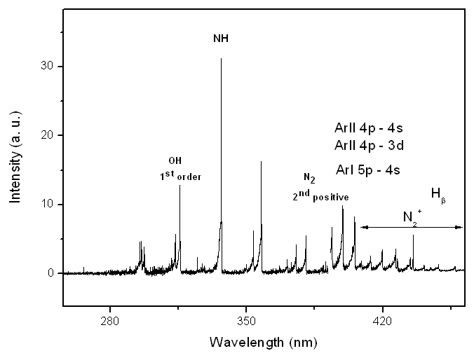 | Figure 3. Emission lines observed on optical spectra of N2 + 1% Ar microplasma jet at a flow rate of 8L/min |
|
4. Conclusions
- The proposed ac APMJ device could produce stable long and cold microjets from various working atomic and molecular gases, as Ar, He, N2, O2 and air. This APMJ was built as a pencil-type device, suitable for various applications and research due to its low gas temperature and low cost materials in use, such as a commercial neon-lamp transformer and air compressor. Boltzmann-plotmethod was performed to estimate the excitation temperature (Texc). The results are: for molecular gases with 1%Ar, Texc = 0.64eV, for pure He, Texc = 0.51eV and for Ar, TAr = 0.60eV. Gas temperature measurements performed at the glow region for 8L/min results as: Tair = 110℃, THe = 100℃, TNitrogen = 120℃, TAr = 120℃ and TOxigen= 130℃. At axial position z = 5 mm from the tip of outer electrode using a thermocouple, Tg is: Tair = 42℃, THe = 32℃, TNitrogen = 40℃, TAr = 45℃ and TOxigen = 48℃. For axial position z = 10 mm, the Tg for afterglow region approaches to the room temperature. The capacity of operation with molecular and atomic (noble) gases, including air, is important for various technological applications, but the novelty of this APMJ is the electrodes performance in spiral-type spring, allowing broadening of the plasma plume at the outer electrode with diameter of 2.5 mmand, consequently, a higher surface area treatment. The APMJ was used for polyethylene (PE) surface modification and this modification was investigated through Water Contact Angle (WCA - θ) measurements. The treatment was done at axial position z = 5 mm from the tip of outer electrode using a range of gases, where the gas temperature was: Tair = 42oC, THe = 32℃, TNitrogen = 40℃, TAr = 45℃ and TOxigen = 48℃. At input power of about 6.0 W and flow rate Φ = 8L/min, for N2, air, O2, He and Ar, θmin (deg) is related to the minimum WCA after the 4 min treatment: N2, θmin = 30; air, θmin = 45; O2, θmin = 70; He, θmin = 35; Ar, θmin = 55.
ACKNOWLEDGMENTS
- The authors acknowledge the financial support of the programs CAPES, FAPESP and CNPq for the partial financial support under Grant No. FAPESP/12/13064-4, CNPq/MCTI/SECIS406035/2013-0, CNPq/310419/2012-3DT and CAPES/88881.030340/2013-01 BJT.