-
Paper Information
- Paper Submission
-
Journal Information
- About This Journal
- Editorial Board
- Current Issue
- Archive
- Author Guidelines
- Contact Us
International Journal of Textile Science
p-ISSN: 2325-0119 e-ISSN: 2325-0100
2017; 6(4): 110-117
doi:10.5923/j.textile.20170604.03

Study on the Various Types of Needle Based and Needleless Electrospinning System for Nanofiber Production
 Abstract
 Reference
 Full-Text PDF
 Full-text HTML
Hosne Ara Begum1, Md. Khalilur Rahman Khan2
1Department of Yarn Engineering, Bangladesh University of Textiles, Dhaka, Bangladesh
2Department of Textile Engineering, Bangladesh University of Business and Technology, Dhaka, Bangladesh
Correspondence to: Md. Khalilur Rahman Khan, Department of Textile Engineering, Bangladesh University of Business and Technology, Dhaka, Bangladesh.
| Email: |  |
Copyright © 2017 Scientific & Academic Publishing. All Rights Reserved.
This work is licensed under the Creative Commons Attribution International License (CC BY).
http://creativecommons.org/licenses/by/4.0/

Nanofibers are fibers with diameters in the nanometer range. The development of nanofibers has greatly enhanced the scope for meeting up the modern world challenges. Currently there are two types of electrospinning systems available for producing nanofiber: needle based electrospinning and needleless electrospinning. This paper summarizes the basic mechanism of various types of needle based and needleless spinning systems described in various literatures by many researchers.
Keywords: Nanofiber, Electrospinning, Needleless electrospinning
Cite this paper: Hosne Ara Begum, Md. Khalilur Rahman Khan, Study on the Various Types of Needle Based and Needleless Electrospinning System for Nanofiber Production, International Journal of Textile Science, Vol. 6 No. 4, 2017, pp. 110-117. doi: 10.5923/j.textile.20170604.03.
Article Outline
1. Introduction
- Nanotechnology is a budding technology that has been identified as a vital scientific and commercial venture with global economic benefits. With the increasing knowledge of nanomaterial manufacturing techniques, research groups around the globe are focusing more on the preparation of nanomaterials for various applications [1]. Nanofibre technology is a technique involving the synthesis, processing, manufacturing and application of fibers with nanoscale dimension [2]. Nanofibers have exciting a new class of material which used for a wide range of applications from medical to consumer products such as, filtration, wound dressing, adsorbent, energy storage, protein separation, immobilization, drug delivery and composites. The main features of nanofibers are large surface area to volume ratio, good mechanical, strength, excellent flexibility, and high porosity. These properties make them suitable for many applications [3].The first attempts at nanofiber production were carried out between 1934 and 1944. The first technology enabling the production of nanofibers appeared on the global market in the 1980s. Donaldson, one of the leading companies in nanofibers based applications brought out the nanofibers first time for advanced commercial applications such as air filtration technology–Ultra Web® in 1981. The full potential of nanofibers technology has yet to be realized in commercial domains. Recent developments in nanofibers production technology has opened up the possibilities of applying nanofibers for various process improvements [4]. Electrospinning has been the most widely used technique in the late 20th (1990) and early 21st (2000) centuries. Electrospinning has been garnering increasing attention in the scientific community, as well as in industry, and is considered to be a vital scientific and commercial venture with global economic benefits. In recent years, some progresses have been made to increase the production rate of electrospinning. For instance, modified single-needle, multi-needle, needleless systems have been improved to increase nanofiber production rate. Needleless electrospinning has been developed to increase the productivity of the electrospinning process by generating multiple fiber forming jets from a polymer solution supported on a suitable support. This technique has been found to produce very encouraging results for bulk scale production of nanowebs [5]. Development in polymer and chemical industries as well as in electronics and mechanics has led to the introduction of new types of electrospinning methods.Combinations of electro and non-electrospinning systems are being utilized increasingly due to the great flexibility provided for producing nanofiber. Centrifugal electrospinning system is a new and efficient method to produce nanofibers quickly. On the other hand, Bubbfil spinning is a promising technology for mass production of nanofiber. Bubbfil spinning is a generalized bubble electrospinning, including bubble spinning, blown-bubble spinning, and membrane spinning, for mass production of nanofiber.This study aims to focus on the basic mechanism of various types of electrospinning system, gas assisted electrospinning and electros and non electro combined mechanism for producing nanoscale fiber. New inventions always depend on comprehensive understanding of already experimented efforts. So the purpose of this paper is to explain the various types of electrospinning mechanism so that researchers can be acquainted and enriched with this knowledge in the way of further modifications.
2. Various Types of Electrospinning
2.1. Basic Needle Based Electrospinning
- Currently, there are two standard electrospinning setups, vertical and horizontal. The typical setup consists of three parts: a) a syringe needle (associated to a syringe and a syringe pump) with a droplet of polymer solution hanging at the tip, b) a ground electrode used as the fiber collector, and c) a high voltage source which creates an electrical potential difference between syringe needle and collector. A polymer solution is pumped through a syringe at a constant rate, forming a droplet at the end of the needle. A high voltage (commonly from 5 to 30 kV) is applied between the polymer solution feed and a collecting electrode. Electric field is subjected to the end of a capillary tube that contains the polymer fluid held by its surface tension. This induces a charge on the surface of the liquid. Mutual charge repulsion causes a force directly opposite to the surface tension. As the intensity of the electric field increases, the hemispherical surface of the solution at the tip of the capillary tube elongates to form a conical shape known as Taylor cone. When the electric field reaches a critical value at which the repulsive electric force overcomes the surface tension force, a charged jet of the solution is ejected from the tip of the cone. The fluid jet is accelerated and stretched by coulombic force exerted the external electric field and becomes dramatically thin while travelling toward the collector, leading to the formation of a continuous solid fiber as the solvent evaporates. Decreasing the jet diameter, the surface charge density increases and the resulting high repulsive forces split the jet into several smaller jets. The jet is seriously elongated by a bending and whipping processes caused by electrostatic repulsion initiated at small bends in the fiber, until it is finally deposited on the collector. Two types of collector may be used, either stationary or rotary collector.
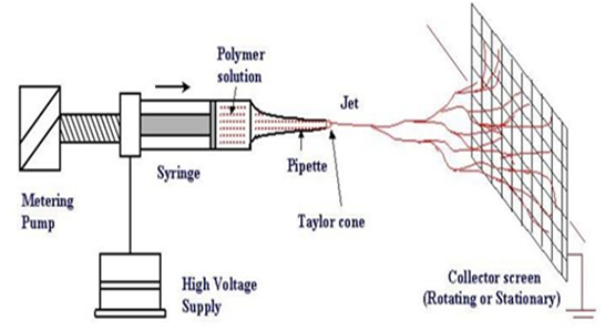 | Figure 1. Basic set-up for needle based electrospinning [6] |
2.1.1. Multi-axial Electrospinning
- Recent efforts in electrospinning are focused on altering the fibers with structural features such as core–sheath, hollow, porous, and tri-axial-channel fibers for use in various applications [7].
2.1.1.1. Coaxial Electrospinning
- Core-sheath fibers are formed by coaxial electrospinning where a coaxial spinneret composed of an outer and inner needle is commonly used. Coaxial electrospinning can generate fibers from various solution pairs, core–sheath, hollow and functional fibers that may contain particles. Hollow fiber constructed using coaxial electrospinning typically with a temporary material as the core and the actual material as the shell. Depending on the post-spinning process, oil is often used as the temporary material as it is relatively easier to remove them than other higher molecular weight material.Based on the basic electrospinning setup (shown in figure-2), two syringes feed inter-separated and coaxial “Inner fluid” and “Outer fluid” to spinneret. Under high voltage, the electrospinning liquid is drawn out from spinneret and forms a “Compound Taylor cone” with a core-shell structure. After “Coaxial jet”, the core-shell structure will be built and kept in the fibers through spinning solid and be collected on the “Collector”.
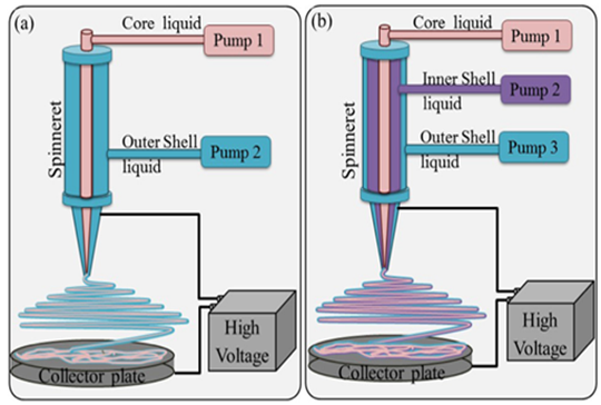 | Figure 2. Multi-axial electrospinning set up showing various components. (a) Co-axial electrospinning & (b) Tri-axial electrospinning [7] |
2.1.1.2. Tri-axial Electrospinning
- In triaxial electrospinning, three polymer solutions are supplied into a compound Taylor cone through a spinneret (fig-2b). Triaxial fibers can be formed with varying hydrophobicity, and mechanical strength.
2.1.2. Bi-component Electrospinning
- The schematic of the bi-component side by side electrospinning is shown in figure-3, where the two plastic syringes each containing a polymer solution lie in a side-by-side fashion. A common syringe pump controlled the flow rate of the two polymer solutions. The platinum electrodes dipped in each of these solutions were connected in parallel to the high voltage DC supply. The free ends of the Teflon needles attached to the syringes were adhered together [8]. An advantage of the side-by-side bi-component fiber is that the single fiber is able to express the characteristics of each of the component of the fiber.
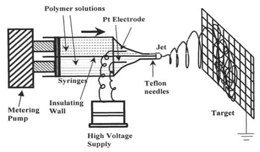 | Figure 3. Side by side bi-component electrospinning set up [25] |
2.1.3. Multi-needle Electrospinning
- The simplest approach to increasing productivity is increasing the number of needles, which is referred as multi-needle electro-spinning.
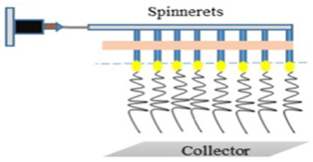 | Figure 4. Multi-needle based electrospinning [26] |
2.1.4. Electroblowing/Gas-assisted/Gas jet Electrospinning
- Electroblowing is a technique combining electrostatic nanofiber production (electrospinning) with airflow around the spinneret. The tangential forces of the flowing air acting on a drop of mixture contribute to the formation of the Taylor cone and to the creation of the nanofiber [9]. With the additional stretching force provided by the gas jet, small diameter fibers have been produced [10]. Combination of forces of electric field applied and the air flow increases the efficiency of the electrospinning process and Air flow accelerates the evaporation of solvent from the solution. This is the only way in which hyaluronic acid can be spun in its native form.
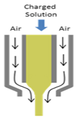 | Figure 5. Gas jet Electrospinning [27] |
2.1.5. Magnetic Field Assisted Electrospinning
- Juan A. Gonzalez Sanchez et al addressed the formation of polymeric nanofibers containing magnetic nanoparticles using electro spinning assisted by a magnetic field. A magnetic field was applied in situ during the electrospinning process. For this purpose, a pair of Helmholtz Coils, each having 200 turns, and carrying a current which varied from 1 A to 3 A were used. The coils were separated with a distance equivalent to the radius of the circular loops (10.5 cm). A step motor was used to turn the sample holder during deposition. By observing the electrospinning process, it can be seen that with the application of the electromagnetic field during fiber deposition, the polymer flow results more oriented towards the target. The nanofibers resulted with a diameter of 100 nm to 700 nm [11].
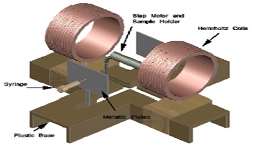 | Figure 6. Magnetic field assisted electrospinning set up [11] |
2.1.6. Conjugate Electrospinning
- The system used in conjugate electrospinning is illustrated in Figure 7. It consists of two or three high voltage power supplies with opposite polarity, two or three spinnerets and a receiver drum. Two or three programmable pumps are used to control the delivery rate of solutions. Power supplies are connected with spinnerets, respectively. Spinnerets are arranged in opposite positions on the same horizontal line. The solution is separately delivered by syringes to two or three spinnerets. The receiver is a rotating drum controlled by a stepping motor. The fibers from the two or three oppositely charged electrospinning spinnerets were collected and stretched by the drum receiver with a constant speed. The nanofiber yarns, which can be produced by this technique, are dried under vacuum at room temperature [12].
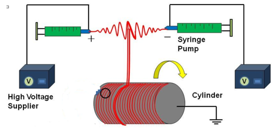 | Figure 7. Conjugate electrospinning [28] |
2.1.7. Centrifugal Electrospinning
- In centrifugal electrospinning, the force contributing to the stretching of the solution drop into fibers are a combination of the centrifugal force and the electrostatic force. Without the application of high voltage, pure centrifugal spinning of fibers require the spinneret to rotate at thousands of rpm. However, in centrifugal electrospinning, the rotation speed can be reduced by 50%. The electric field contributes to stretch the jets to very small dimensions under simultaneous evaporation of the solvent, leaving a dry nano-fibrous coating on the substrate. With the introduction of centrifugal force, a lower voltage is required to overcome the surface tension of the solution to initiate electrospinning. The combination of mechanical rotation and the reduced voltage makes this a very effective method for fabricating aligned nano-fibers. Multiple nozzles may be placed around the axis of rotation to increase the production rate of centrifugal electrospinning [13].
 | Figure 8. Centrifugal spinning setup [29] |
2.2. Needleless Electrospinning
- Nevertheless, common ES techniques based on the use of a syringe produce nanofiber layers in quantities of approximately 0.1–1 grams per hour. Needleless electrospinning allows industrial-scale production of nanofibers [14].
2.2.1. Bubble Electrospinning
- Bubble-electrospinning was invented in 2007 [15]. Bubble electrospinning, as one of the simple and effective techniques that have potential for large scale production of continuous nanofibers with diameter range from several nanometers to micrometers [16]. Fig. 9 shows the schematic of a classical bubble spinning set-up, which includes a bubble generator, a spinneret, an air pump, a solution reservoir, a high-voltage power supply, and a grounded collector.
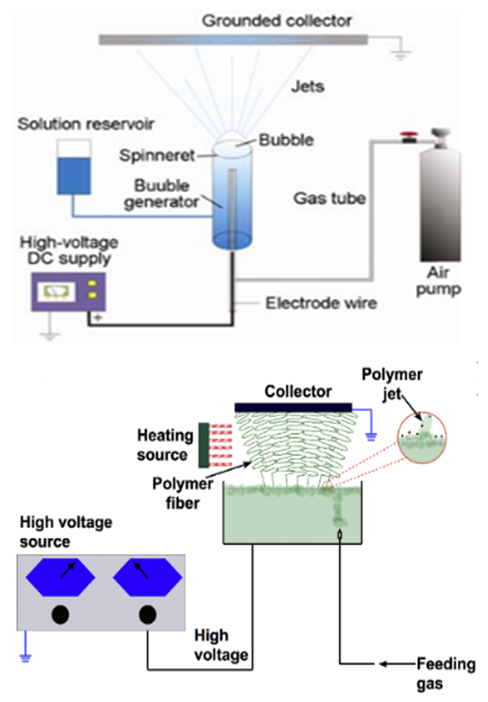 | Figure 9. Classical bubble spinning set up. (a) Single bubble electrospinning & (b) Multi-bubble electrospinning [30] |
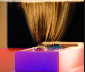
2.2.2. Two Layer Fluid Electrospinning
- A two-layer system, with the lower layer being a ferromagnetic suspension and the upper layer a polymer solution, is subject to a normal magnetic field provided by a permanent magnet or a coil. As a result, steady vertical spikes of magnetic suspension perturbed the interlayer interface, as well as the free surface of the uppermost polymer layer. When a normal electric field is applied in addition to the system, the perturbations of the free surface become sites of jetting directed upward. Multiple electrified jets undergo strong stretching by the electric field and bending instability, solvent evaporates and solidified nanofibers deposit on the upper counter-electrode, as in an ordinary electrospinning process. However, the production rate is shown to be higher [18].
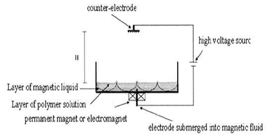 | Figure 10. Two layer fluid electrospinning [19] |
2.2.3. Splashing Electrospinning
- A solution reservoir is used to provide spinning solution to a metal roller electrospinning spinneret. The polymer solution droplets were splashed onto the surface of a metal roller by a solution distributor, which had a hole at the bottom. When the voltage was applied, solution droplets adhering on the surface of metal roller spinneret were ejected and stretched under the electric force to form nanofibers. This setup was proposed to have the ability to perform electrospinning with improved fiber production rate [19].
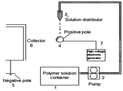 | Figure 11. Splashing electrospinning setup [19] |
2.2.4. Melt Differential Electrospinning
- With the Melt differential electrospinning, fibers with diameter smaller than one micrometer can be produced at a yield of 10-20g/h using a needleless nozzle. The process was described as follows: firstly the supplied polymer melt was distributed to the surface of umbellate (cone-like) nozzles, next the melt film covered uniformly over the umbellate circumferential surface. When the applied high voltage surpassed a critical value, self-organized multiple jets around the rim of the umbellate nozzle were ejected to the receiver plate. This process is given the name MD-ESP due to the melt flow dividing into tens of minor Taylor-cones as a result of their self-organization. A high voltage was applied directly to the collector instead of the needle or nozzle and this allows the separation of the heating system and electrodes [20].
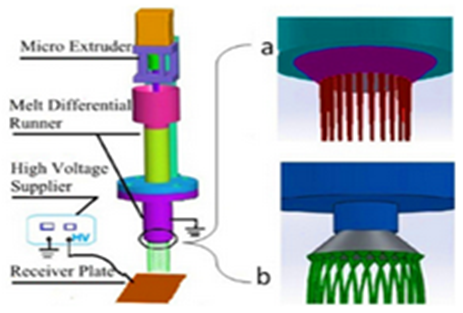 | Figure 12. A schematic diagram of melt differential electrospinning (inner cone and out-cone nozzle) [31] |
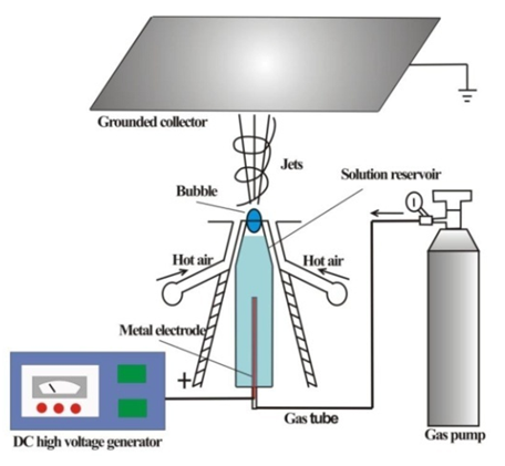
2.2.5. Gas Assisted Melt Differential Electrospinning
- The hot air assisted melt differential electrospinning is a new technique. Apparatus consists of six major parts as shown in (Figure 13): power supply of high-voltage, heating system, an air pressure gun, a copper circular ring functioning as electrode A, a needleless cone-shaped nozzle, and a collecting device. he function of hot air can be summarized into three main points: Preserving heat of runner, accelerating thinning of flying jets, and keeping the environmental temperature high, that's higher than the softening point which will increase the action time of electric force and reduce fiber diameter. The unique features of the apparatus are: the generation of multiple Taylor cones around the bottom edge of the nozzle, resulting in a high throughput; the air current driven by an air pressure gun further strengthened the stretching force acting on the jets. More importantly, it could contract the flying jets with the pressure difference between the air current and the atmosphere to prevent the polymer jets from being attracted by the inner circle of electrode [21].
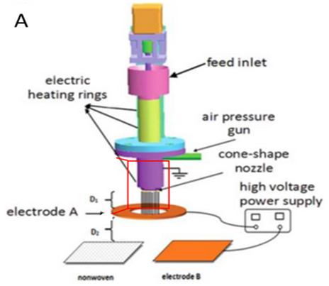 | Figure 13. Gas assisted melt differential electrospinning [32] |
2.2.6. Rotary Cone Electrospinning
- Bingan Lu et al reported a needleless electro- spinning setup using an electriferous rotating cone as the spinneret. The production throughput of this approach was about 10 g/ min, which was several thousand times higher than that by traditional electrospinning technique with a single needle as the spinneret. A schematic of this high-throughput electrospinning system is shown in Figure 14. It consisted of four major components: a high-voltage power supply, a metallic cone, a direct-current (DC) electromotor, and a collector. When using an aluminum conveyor belt as the collector, the resultant electro spun nanofiber membrane was very long. When one drop of the PVP solution was transferred to the surface of the cone, it could be electrified with positive charges immediately. The charged liquid droplet would flow along the rotating surface under the coactions of gravity, the moment of inertia, and the electric force. Once the liquid droplet reached the lower edge of the cone, the electrospinning process started [22].
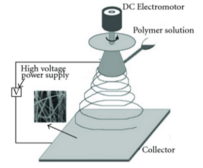 | Figure 14. Rotary cone electrospinning [33] |
2.2.7. Rotating Roller Electrospinning/ Nano Spider Technology
- Nanospider is a modified electrospinning method which requires the use of a high-voltage electrostatic field to create an electrically charged stream of polymer solution or melt. The innovatory idea of the Nanospider is based on the possibility of producing nanofiber from a thin layer of liquid polymer. In this case, Taylor cones (the source of nanofiber) are created on the surface of a rotating roller, immersed in a polymer solution. Because the Taylor streams are formed next to each other, throughout the entire length of the roller, this revolutionary idea produced many advantages, such as high productive ability. This commercial method for production of polymeric nanofiber is used in industrial range. This is a simple and versatile method for production of ultrathin fibers from a variety of materials that include polymers. In addition, Nanospider has the ability to process a wide range of polymers in diameters of 50–300 nm into nonwoven webs [23].
 | Figure 15. Rotating Roller electrospinning [34] |
2.2.8. Edge Electrospinning
- N M Thoppey et al. demonstrated Edge electrospinning consisting of the fluid-filled bowl, a positive polarity high voltage power supply and a concentric, cylindrical grounded collector. Multiple jets are initiated spontaneously from the polymer fluid directly at the lip of the bowl, as well as further inside the bowl’s interior which then migrate to the edge and organize to form relatively equally spaced spinning sites around the bowl circumference. The bowl itself serves as the source of the polymer solution instead of gravity-assisted fluid streams. An initial brief high voltage interval aids in forming the jets; subsequently, the voltage is reduced to a lower operating value for stable electrospinning and nanofiber formation. The collected fibers exhibit properties similar to those fabricated under optimal needle electrospinning conditions. This simple bowl-spinning approach is applicable to a variety of polymers in aqueous and non-aqueous-based solvent systems and to polymer solutions having differing viscosities. The collector surface is covered with conductive aluminum foil in order to easily remove the electro spun mat samples [24].
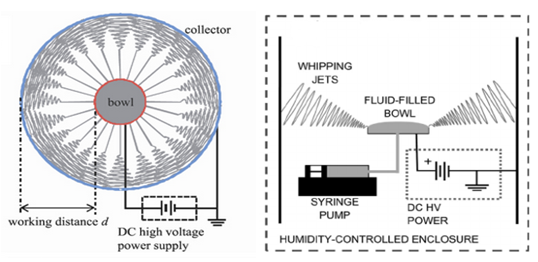 | Figure 16. Edge Electrospinning [35] |
2.2.9. Blown Bubble Electrospinning
- A polymer liquid membrane is produced by a metal ring rotating through the polymer solution, and the membrane is pulled forward by a blowing air to form a bubble under the presence of a high electronic field.
 | Figure 17. Blown bubble electrospinning [36] |
3. Conclusions
- Although electro spun nanofibers have shown enormous application potential in diverse areas, the lower production rate of needle based electrospinning has forced researchers to open the door for new needleless techniques for producing nanofiber by forming multiple jets from a polymer solution supported on a suitable support. Needleless spinning systems also play an important role in decreasing the fiber diameter in general. However, using electrostatic force in non-electro spinning method such as centrifugal spinning method have created new possibilities for commercial production of nanofiber. It is also worth mentioning that airflow assisted electro spinning methods have also gained deep attention because of their latent opportunities in the field of nanofiber technology.