Bilal Zahid1, 2, Xiaogang Chen2
1Textile Engineering Department, NED University of Engineering and Technology, Karachi-75270, Sindh, Pakistan
2The University of Manchester, M139PL, Manchester, United Kingdom
Correspondence to: Bilal Zahid, Textile Engineering Department, NED University of Engineering and Technology, Karachi-75270, Sindh, Pakistan.
| Email: |  |
Copyright © 2012 Scientific & Academic Publishing. All Rights Reserved.
Abstract
It has been already established that continuously textile reinforced helmet shells have shown its significance over discontinuous helmet shells. This paper is a part of research carried out for the evaluation of riot helmet shells having continuous textile reinforcement. ABAQUS, finite element software, has been used for simulationand model creation. Force transmitted and energy absorption at three different impact locations of the helmet shells were evaluated from the finite element model and validated by experimental testing. Significant correlation in between finite element results and physical impact testing results has been achieved. The finite element outcomedisplays the helmet top location is the least susceptiblelocation against the impact as compared to the helmet side and helmet back location.
Keywords:
Helmet Shells, Continuous Textile Reinforcement, Finite Element, ABAQUS, Simulation, Energy Absorption, Force Transmitted
Cite this paper: Bilal Zahid, Xiaogang Chen, Energy Absorption at Different Impact Locations of Riot Helmet Shells, International Journal of Textile Science, Vol. 2 No. 4, 2013, pp. 126-131. doi: 10.5923/j.textile.20130204.07.
1. Research Background
Not much literature has been written on the continuously textile reinforced helmets[1]. An innovative, effective and modest method of making a single-piece continuous textile reinforced helmet shell using vacuum bagging has been established and discussed by Zahid and Chen[2]. A number of wrinkle-free single-piece composite helmet shells from angle-interlock fabric have been manufactured from the modified vacuum bagging technique. Furthermore, mechanical and physical properties of the developed composite structures from angle interlock fabric has been calculated and analysed[3]. These properties can be used in making a finite element simulation. A single-piece continuously Kevlar reinforced helmet shell can be viewed in Figure 1[2].In order to evaluate an impact performance of produced helmet shells, an impact test rig was developed[4]. Sensors were mounted on side, back and top of the testing headform developed following the standard BS EN 960:2006[5]. The developed test rig can be seen in Figure 2. The experiments were also conducted and published[4].In the drop weight system, potential energy of the system is converted into kinetic energy during an impact onto the sample. Energy absorption can be calculated by integrating the closed area of the load deflection curve[6]. Force transmitted can be used for the evaluation of forceattenuation factorwhich has been discussed by several authors[6-9]. A lesser value of attenuation factor corresponds to largerimpact force being transmitted through the specimen (0% means all forces transferredand 100% means no force transferred). | Figure 1. Single-piece helmet shellhaving continuously textile reinforcement |
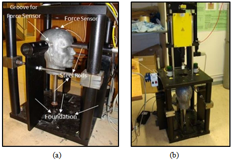 | Figure 2. Helmet test rig (a) side view (b)front view |
2. Research Objectives
The literature review recommends that finite element analysis is a dynamic tool for the virtual investigation, since a validated FE model from experimental results will give a deeper understanding[10, 11]. Therefore, in current research paper, finite element (FE) method was used to model helmet shells, results of which are compared and validated by the published experimental results[4]. ABAQUS software was chosen for generating simulations due to its Microsoftwindows interface and also due to availability in the University of Manchester.For present study, the basic idea was to calculate the impact energy absorbed and force transmitted by the composite laminates through simulated models. Moreover, results have to be validated from the experimental data.
3. Model Creation and Simulation
In this research,impact performance with respect to force transmission and energy absorption, at different impact locations on the helmets shells are investigated. Physically riot helmet shells were tested on the developed helmet testing instrument and virtually by means of FE simulation at ABAQUS software. Focus of current research is the energy absorption instead of damage mechanism. Abaqus / Explicit method was used in order to develop simulation. In this study the ABAQUS/Explicit product was used which has three stages, which includes; pre-processing, simulation and post processing. One of the advantages of ABAQUS/Explicit as used is that it can convert or import geometries in to the ABAQUS/CAE environment. Further, ABAQUS/Explicit is used for simulating impact problems [12]. In current study, the simulated different parts have been developed in Rhinoceros software and then imported to Abaqus.The helmet shell created in Rhinoceros softwarecan be seen in Figure 3.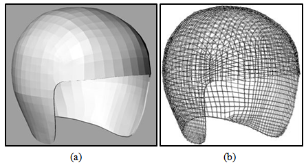 | Figure 3. Developed riot helmet shell in Rhinoceros Software (a) with render (b) without render |
Similarly, the headform coordinates were sourced from EN 960:2006 standard[5] and generated via Rhinoceros. The headform was given details of a solid material having aluminium properties. Aluminium headforms are normally used by several authors[13-15]. Developed headform can be viewed in in Figure 4.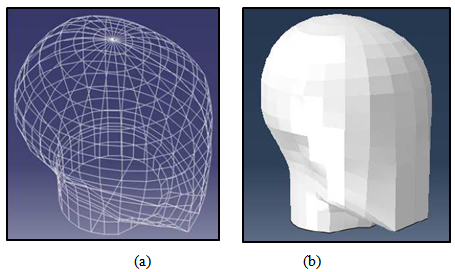 | Figure 4. Development stages of Headform(a) Wire structure headform (b) Solid headform |
The impactor was generate and designed in ABAQUS as in Figure 5, as a flat rigid cylindrical impactor of mass 4.66 kg.The dimensions of the impactor were 25 mm diameter and 67.5 mm height, similar to the impactor used in experimental tests.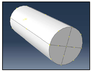 | Figure 5. Flat impactor |
A small part was created and attached on the top of the headform by means of a tied command in ABAQUS, similar to the force sensor used in experimental analysis. The properties for the helmet shell were obtained from the research work by Zahid and Chen[3] and calculated according to the method considered by several authors[12, 16, 17].Kevlar Composite Material, density ρ = 1.229 gm/cm3Modulus, weft direstion, E1 = 36938.301 MPaModulus, warp direction, E2 = E3 = 7793.701 MPaPoisson Ratio (weft to warp), ν12 = ν 13 = 0.356Poisson Ratio (warp to weft), ν21 = 0.075Poisson Ratio (warp to thickness), ν23 = 0.108Inplane Shear Modulus, G21 = G12 = G13 = 1379.255 MPaInplane shear, warp to thickness, G23 = 3516.808 MPaWhere,ν12 = (vf x Vf) + (vr x Vr)ν21 = (E2 / E1) x ν12ν23 = ν12 x ((1 – ν21) / (1- ν12))G23 =[(E2) / {2 x (1+ ν21)}] Vf is Poisson ratio, Kevlar 49[18] = 0.36Vr is Poisson ratio, Aradur 5052 andAraldite LY5052[19] = 0.35 In this model a tetrahedral shape mesh is used because it is the appropriate mesh shape for three dimensional parts[12]. Encastre boundary conditions were given at the neck and helmet shell edge as shown inFigure 6. A cross sectional view of the simulated model in Abaqus CAE environment can be viewed in Figure 7.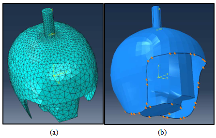 | Figure 6. Simulatedpictures (a) Meshed parts (b) Boundary conditions |
 | Figure 7. Cross-sectional view of the simulated model |
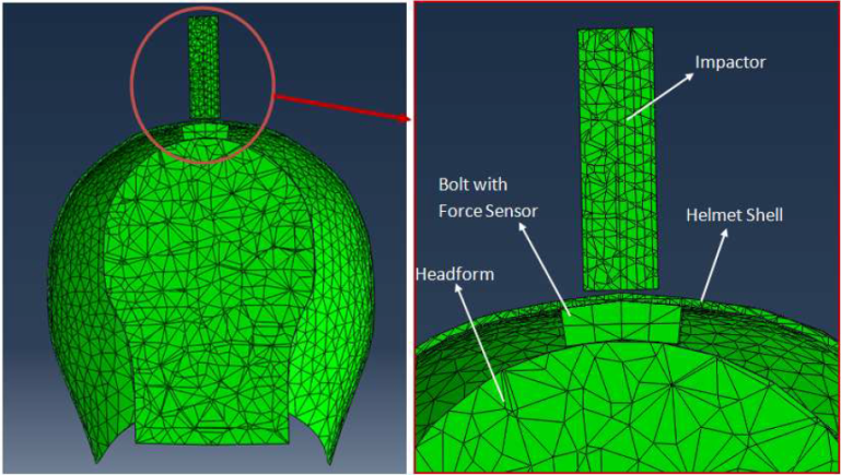
A simulated model can be seen in Figure 8.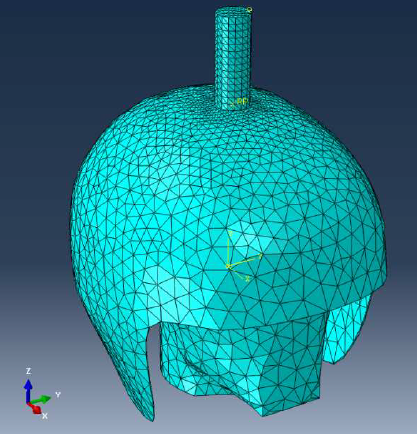 | Figure 8. Top impact helmet location |
4. Simulated Results and Validation with Experimental Results
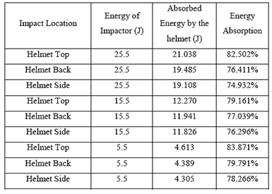
Finite element (FE) simulation has been executed with three different impact energies 5.5J, 15.5J and 25.5J. Impact was conducted at three different locations on the developed helmet shells namely, the top location, the back location and the side location. The results generated from the simulated modelswere put together with the corresponding experimental results to look for similarities between them. In this way 9 models have been simulated and the results for the percentage energy absorption are illustrated in Table 1.Table 1. Simulated results of helmet shells for energy absorption
 |
| |
|
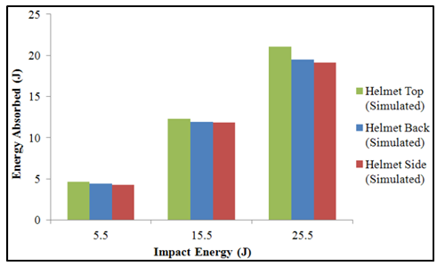 | Figure 9. Energy absorbed by the helmet shell at different locations |
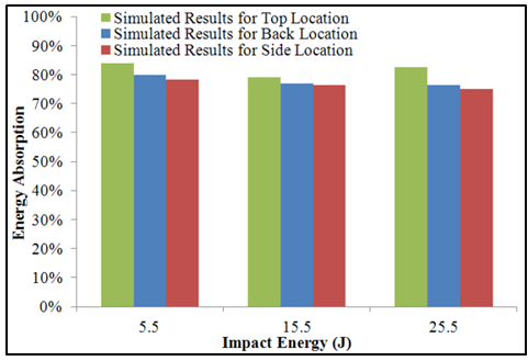 | Figure 10. Percent energy absorption for helmet shell |
Figure 9 and Table 1shows that with higher energy impacts, helmet top surface absorbs more impact energy. The helmet shell side absorbs the least amount of energy. At every location energy absorption is increased with the increase of impact energy. Moreover, the percentage energy absorption in Figure 10 also shows similar trends at each energy level. These results show that the helmet top location is the least vulnerable position against impact. More importantly, these results are very similar to the results obtained from the experimental test data and are compared in Figure 11.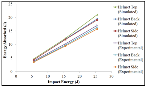 | Figure 11. Comparison of energy absorption results for helmet shells at different helmet locations |
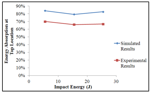 | Figure 12. Percent energy absorption at Top location of helmet shells |
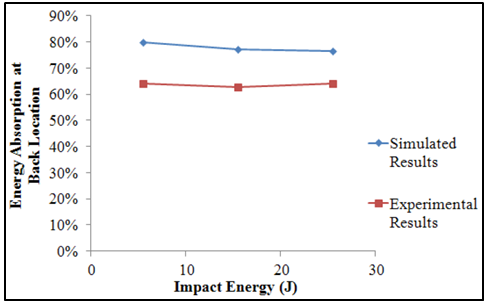 | Figure 13. Percent energy absorption at Back location on helmet shells |
Figure 11 show that the simulated energy absorption has similar trends as compared to the average experimental results. The top location seems to absorb more impact energy as compared to the other two locations. This may be due to the fact that the top impact location is at greater distance from the shell edge as in comparison to other locations.It can be observed that simulated and experimental percentage energy absorption shares similarities. The results for percentage energy absorption in Table 1 are compared with the experimental testing and shown in Figure 12, Figure 13 and Figure 14. Simulated results have greater values than experimental results, and simulated trends are near and similar to the experimental results.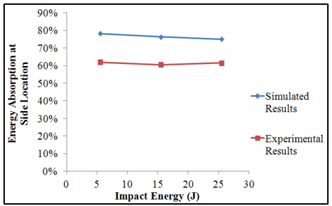 | Figure 14. Percent energy absorption at Side location on helmet shells |
The force transmitted at different helmet locations has been obtained and compared with the experimental results. Force transmitted has been obtained from the top surface of the force sensor which touches the inside surface of the helmet shell. In Figure 15, Figure 16 and Figure 17, it can be observed that the force transmitted also has a similar trend. However, there is difference in the magnitude of the peak force transmitted. This seems to be true being due to the fact that in simulations the helmet shell has been taken as one composite entity with a solid surface whereas, in reality the composite structure is made-up from AI-fabric which transfers the load throughout its inherent weave structure. Moreover, the reason to explain this kind of difference could be that FE simulation is a much simpler approach to the real situation.  | Figure 15. Force transmitted results at Top location on helmet shells |
Impact performance of the helmet shells having continuous textile reinforcementcan be characterised by the impact location. From the experiments both virtual and physical, the helmet top position appears to be the least susceptible impact position on the helmet shell. It should be noted that the distance of the impact top location from the shell edges is larger than the side and back impact locations. Due to fact the impact at the top impact location is dispersed to a wider area and causes better impact performance. Due to this reason, to bend the helmet top surface, more impact force is required and due to this reason usually less force will be transmitted to the head. Moreover, due to the advantage of single-piece continuously textile reinforcement and no discontinuity till the shell edges, makes the helmet top impact position to be least threatening impact position. The helmet side and back impact locations attract more attention compared to the top location for better impact performance. Improving the helmet shell stiffness could result in better impact performance. 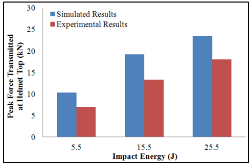 | Figure 16. Force transmitted results at Back location on helmet shells |
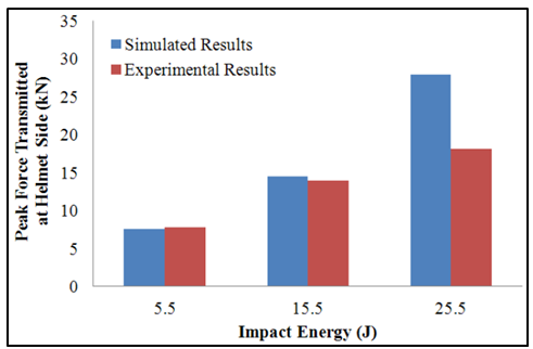 | Figure 17. Force transmitted results at Side location on helmet shells |
5. Conclusions
The research was carried out to develop an impact simulation and its validation through practical testing. The simulated models were validated by the experimental data. The results revealed that the simulation generally correspond and shows the similar trends as the experimental results although there are some imprecisions due to the simplification of the simulated model compared to the real impact on the developed helmet shells. Impact simulation shows similar energy absorption trends as compared to the experimental results. The helmet top impact has been to be the safest position in respect of low energy impact if compared to the helmet back and the helmet side locations. Creation of models in ABAQUS has shown an effective way of analysing the impact properties of a riot helmet shell in terms of energy absorption and force transmission.In this paper successful riot helmet shell models have been generated and developed impact simulations were successfully validated by experimental results.
6. Funding
This study was financially supported by NED University of Engineering and Technology, Karachi, Pakistan.
References
| [1] | Roedel, C. and X. Chen, Innovation and analysis of police riot helmets with continuous textile reinforcement for improved protection. Journal of Information and Computing Science, 2007. 2(2): p. 127-136. |
| [2] | Zahid, B. and X. Chen (2012) Manufacturing of single-piece textile reinforced riot helmet shell from vacuum bagging. Journal of Composite Materials, DOI:10.1177/0021998312457703. |
| [3] | Zahid, B. and X. Chen (2012) Properties of 5-layer angle-interlock Kevlar-based composite structure manufactured from vacuum bagging. Journal of Composite Materials, DOI: 10.1177/0021998312463457. |
| [4] | Zahid, B. and X. Chen (2013) Impact performance of single-piece continuously textile reinforced riot helmet shells. Journal of Composite Materials, DOI:10.1177/0021998313477173. |
| [5] | The European Standard, Headform for use in the testing of protective helmets BS EN 960:2006. |
| [6] | Gong, X., Investigation of different geometric structure parameter for textile honeycomb composites on their mechanical performance. 2010, The University of Manchester. |
| [7] | Maach, I.E., et al., Forces resulting from bat impact on the chest of adult human hybrid do not depend on the torso inertia. 2004, Med-Eng Systems, Ottawa, Ontario, Canada. |
| [8] | Robinovitch, S.N., et al., Hip protectors: Recommendations for biomechanical testing — an international consensus statement (part I). Osteoporosis International, 2009. 20. |
| [9] | Dionne, J.P., et al., Performance of crowd management shin guards subjected to ball and baseball bat impacts. 2002, Med-Eng Systems, Ottawa, Ontario, Canada. |
| [10] | Kormi, K. and R.A. Etheridge, Finite element analysis - application of the finite-element method to simulation of damage to the human skull as a consequence of missile impact on a multi-layered composite crash helmet J. Biomed, 1992. 14. |
| [11] | Her, S.-C. and Y.-C. Liang, The finite element analysis of composite laminates and shell structures subjected to low velocity impact. Composite Structures, 2004. 66: p. 277-285. |
| [12] | The University of Manchester.http://www.applications.itservices.manchester.ac.uk/medialibrary/docs-abaqus/GET_STARTED.pdf. 2009[cited 2010]. |
| [13] | Becker. Guided fall impact test deviceshttp://www.smf.org/docs/articles/dot_reply_08/mo_tw2.pdf. 1997[cited 2011]. |
| [14] | Mills, N.J., Protective capability of bicycle helmets. group.bmj.com, 2011. 24. |
| [15] | Mills, N.J. and A. Gilchrist, Oblique impact testing of bicycle helmets. Imternational journal of impact engineering, 2008. 35. |
| [16] | Kaw, A.K., Mechanics of composite materials. 2nd ed. 2006: Taylor & Francis. |
| [17] | Mallick, P.K., Fiber-reinforced composites materials, manufacturing and design. 3rd ed. 2008: Taylor & Francis Group, LLC. |
| [18] | Kevlar. Technical guide Kevlar Aramid Fiber. 2011 2011[cited 2011]; Available from:http://www2.dupont.com/Kevlar/en_US/assets/downloads/KEVLAR_Technical_Guide.pdf. |
| [19] | Huntsman. www.huntsman.com. 2010[cited 2011]. |
 Abstract
 Reference
 Full-Text PDF
 Full-text HTML