Muhammad Dawood Husain1, Ozgur Atalay2, Richard Kennon2
1Textile Engineering Department, NED University of Engineering & Technology, Main University Road, Karachi, 75270, Pakistan
2School of Materials, University of Manchester, Manchester, UK
Correspondence to: Muhammad Dawood Husain, Textile Engineering Department, NED University of Engineering & Technology, Main University Road, Karachi, 75270, Pakistan.
| Email: |  |
Copyright © 2012 Scientific & Academic Publishing. All Rights Reserved.
Abstract
This article reports the effect of strain and humidity on the performance of newly developed Temperature Sensing Fabric (TSF) in the laboratory environment. Temperature Sensing Fabric is a double layer knitted structure; made of polyester as a basal yarn and embedded with fine metallic wire as sensing element. Fabricated on an industrial scale computerised knitting machine, the TSF samples made of nickel, tungsten and copper wires in the form of bare and insulated form were used in this study. In order to analyze the performance of TSF under variety of strain and humidity environment, tailor-made methods were devised, as relevant standards were not available. In strain testing, the TSF samples made of insulated sensing wire performed better in comparison to the samples made with bare sensing wires. Results of the humidity testing revealed that all kinds of TSF samples (either made of sensing elements of insulated wire or bare wire) could be used in a high humidity environment (up to 90% RH) without any compromise in their sensing performance.
Keywords:
Temperature Sensing Fabric, Temperature Sensor, Resistance Temperature Detector, Textile Sensors, Strain Sensing, Humidity Sensing
Cite this paper: Muhammad Dawood Husain, Ozgur Atalay, Richard Kennon, Effect of Strain and Humidity on the Performance of Temperature Sensing Fabric, International Journal of Textile Science, Vol. 2 No. 4, 2013, pp. 105-112. doi: 10.5923/j.textile.20130204.04.
1. Introduction
This paper presents part of the research carried out for the development of Temperature Sensing Fabric (TSF) for physiological monitoring of human body. The TSF was made by embedding a fine metallic wire as sensing element into the double layer knitted structure of polyester on an industrial scale flat bed knitting machine[1][2]. One of the research objectives was to evaluate the effect of external parameters on the performance of TSF. For the said purpose, this study was carried out by subjecting the TSF into various strain and humidity environments and by examining its performance.
1.1. Wearable Health Monitoring Systems (WHMS)
The physiological monitoring of the human body includes the measurement of standard vital signs such as respiration movement, cardiac activity, pulse oxymetry and body temperature. The vital signs describe the status of the health of the human body. Each vital sign has its respective role in diagnosis of the disease and management of the disease process[3]. For instance the information of the abnormal body temperature can be an indicator of illness at an initial stage and can be a useful guide to take suitable action[3, 4]. Researchers all over the world are making efforts to enhance the quality of patient’s life by improving their mobility and reducing the hospitalization costs. This resulted in the development of range of prototypes of monitoring systems for variety of end users which is commonly known as Wearable Health Monitoring Systems (WHMS)[5-8].
1.2. Temperature Sensing Fabric (TSF)
TSF was developed by keeping in mind its integration with the WHMS so that it can be deployed to measure the temperature of the human body on continuous basis for extended periods without any hassle to the wearer. Temperature sensing fabric was designed on the conceptual basis of Resistance Temperature Detector (RTD) and fabricated on an industrial scale computerised flat-bed knitting machine. Few individual studies have also been reported towards the development of textile based temperature sensors[9-13]. However these studies are preliminary in nature i.e. sensor was made of manual procedure and was limited in characterization.A conceptual illustration of TSF showing embedded sensing wire in a rib structure is shown in Figure 1, where L and W represent the length and width of the TSF respectively. The working principle of the TSF is based on the fundamental tendency of the metal wire to vary its electrical resistance due to the change in its temperature. The metal wire is embedded approximately in the middle of a double layer structure; therefore it is hardly noticeable and does not affect the aesthetics of the fabric. The compact double layer structure of the TSF also provides shield to the metal wire from wearing away. The TSF samples were developed with an 8 cm x 8 cm sensing area. After much experimental trials, the highest wire inlay density that was successfully attained was of 46 wire inlays in an 8 cm x 8 cm sensing area (≈ 3.8 meters length of wire)[1].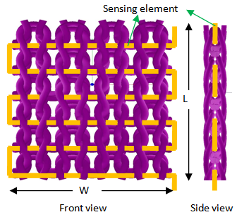 | Figure 1. A conceptual illustration of TSF showing embedded sensing |
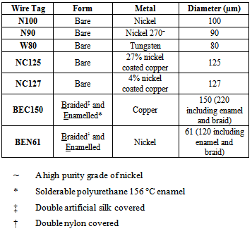
Various types of metal wire could be employed as the sensing element of a TSF. Nickel, tungsten and copper wires were selected[1] as the sensing elements for the TSF samples, because of their high temperature coefficient of resistivity, and to take benefit of their linear temperature-resistance relationship between 0°C and 100°C. These sensing elements, in the form of bare and insulated wires, in different diameters were used in the fabrication of the TSF as shown in Table 1.Table 1. Sensing elements used in the fabrication of Temperature Sensing Fabric[1]
 |
| |
|
1.3. Rationale of this Study
Since the working principle of the TSF is based on the fundamental tendency of the metal wire to vary its electrical resistance due to the change in its temperature. Therefore in order to create the relationship between the resistance (dependent variable) and temperature (independent variable) of the sensing fabric, samples were tested in various thermal environments, under laboratory conditions[1, 2]. The intended application of the TSF is the measurement of human body skin temperature. For that purpose, TSF can be integrated into the next-to-skin garment. During the laboratory temperature-resistance testing, the TSF samples were kept stationary in a test rig and humidity of the environment was maintained within the range of 40% ± 5% R.H. However, unlike the laboratory environment, the intended application of the TSF is dynamic in nature. That means the TSF performance may deteriorate because of its placement in close proximity to the humid skin environment. Due to evaporation of sweat from the skin of the human body, the relative humidity next to the skin tends to be higher than the relative humidity in the environment[14, 15]. The presence of high humidity near the skin may increase the moisture content of the TSF and affect the sensing characteristics of the TSF.Similarly TSF performance may also deteriorate because of the breathing and body movement. Because of this TSF may experience some mechanical loads, which can disturb the inlaid wire, resulting in resistance variations because of either wire-to-wire contact along the edges of the TSF, or change in resistivity of the metallic wire by permanent deformation of its molecular lattice[16, 17]. Under extreme load conditions, a TSF may fail to perform because of wire breakage. Before using a TSF for skin temperature measurement, it was therefore important to investigate the effect of different mechanical effects (such as tensile force and bending) and humidity on the performance of the TSF in the laboratory environment. This article presents the results of the effect of strain and humidity on the performance of the TSF in the laboratory environment.
2. Effect of Strain
2.1. Methods and Materials
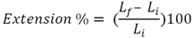
Two kinds of strain test i.e. tensile and bending were performed on a purpose-designed test rig. Since, there was no standard available to be used as a benchmark to perform the strain test; a specifically-designed test rig was developed. The test rig (strain rig) was designed by considering the following requirements:• it should provide standard repeatable testing conditions (such as different levels of extension and bending of TSF); and• it should not impede the strain and resistance measurement process. The strain-rig was made with a pair of jaws, one of which was moveable, guided by parallel tracks fastened on a wooden board as shown in Figure 2. The clips were mounted on both jaws to hold the TSF fabric by its non- sensing area. One of the jaws was fixed while the other jaw was allowed to move to produce the required stretch or bend in the fabric. Tensile and bending tests were performed on the strain-rig by the displacing the movable jaw from its initial position. Moving the moveable jaw away from the fixed jaw produced extension in fabric, while bringing it towards the fixed jaw produced a bend in the fabric. In order to measure the length of a TSF fabric during a tensile test, a length measurement scale was also marked beside the tracks. In order to see the effect of any independent variable on other dependent variables, it is important that remaining independent variables should be uniform during the test. Similarly, in order to quantify the strain-dependent resistance, the TSF temperature should be constant throughout the test; otherwise it would add error to the measurement. Since the setting of the jaw position involved manual handling which may increase the TSF temperature because of transfer of heat from the human body to the TSF: therefore a five minute pause was allowed between each new setting of the jaw position so that the TSF could regain thermal equilibrium with the room An Agilent 34401A multimeter (Figure 3) along with a four-wire resistance measurement connector was employed to measure the TSF resistance during the strain testing.Tensile Test Procedure: The tensile test was performed by exerting the tensile forces on a non-sensing area of the TSF (by moving the adjustable jaw away from the fixed jaw) as shown in Figure 4 and by manually measuring the extension of the TSF fabric along with the corresponding resistance. The extension of the TSF sample was calculated by considering the initial Li and final Lf lengths of the TSF (distance between the clamps):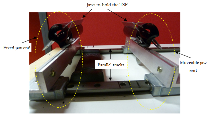 | Figure 2. Test rig for the strain testing (Tensile and Bending) |
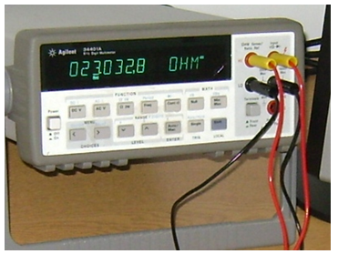 | Figure 3. An Agilent Bench-top multimeter along with 4 wire resistance measurement setup |
 | (1) |
Bending Test Procedure. The bending test was performed by producing a bend in the sensing area of the TSF by moving the adjustable jaw towards the fixed jaw as shown in Figure 5 and by manually measuring the bending height of the TSF fabric along with the corresponding resistance. Image A of Figure 5 shows the various levels of bending test. The height of bending curvature (as shown in image B of Figure 5) can be related to the bending stresses experienced by the TSF. The height of bending curvature was calculated from the neutral position when the TSF was in a relaxed condition before the test.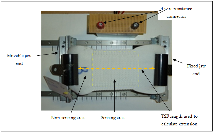 | Figure 4. Tensile strain testing on strain-rig |
 | Figure 5. Bending strain testing on strain-rig |
2.2. Result and Discussion
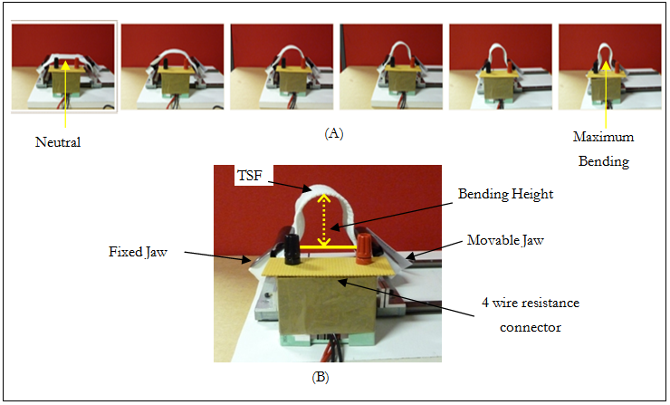
Figure 6 and Figure 7 present the TSF performance during extension and bending, respectively. For ease of understanding and comparison, the resistance values acquired during the strain tests were converted into temperature by making use of the calibration equation for the respective TSF sample. From the results of both bending and tensile testing, it can be seen that TSF samples made with bare wire sensing elements (such as nickel, tungsten and nickel-coated copper) showed more variation in their resistance in comparison with the insulated sensing elements (such as braided, enamelled copper and nickel). These variations can be attributed to the wire-to-wire contact at the edges due to the unsatisfactory bending of the sensing element during TSF manufacturing[1] as shown in Figure 9. When the fabric is strained, the bending region along the edges may induce errors by making or losing wire-to-wire contact. It is important to note that wire-to-wire shorting problems were only observed along the edges. If the sensing element touches itself in the main sensing area, then a large variation in resistance would occur. | Figure 6. TSF performance during a tensile test |
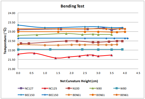 | Figure 7. TSF performance during a bending test |
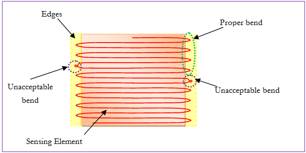 | Figure 8. Proper and improper bending of sensing element along the edges of TSF sample |
3. Effect of Humidity
3.1. Methods and Materials
In order to study the influence of high relative humidity on the sensing performance of the TSF, following instruments were employed: a multimeter (for the measurement of TSF resistance); an Oregon Scientific Weather Station (for measurement of room temperature and humidity); and a digital balance (for measurement of the TSF mass).All experiments were performed in a conditioned laboratory (equipped with Mitsubishi Mr. Slim air conditioner and Hygromatik hygrometer) in which a thermal environment of 30 to 90% Relative Humidity (RH) was created at a room temperature of 20°C. The initial laboratory RH level of 65% was raised to 90% by adjusting the Hygrometer settings. After the laboratory achieved the 90% RH and maintained it for an hour, the environment temperature and the mass & resistance of the TSF were noted. After that Hygrometer was turned off, allowing the RH level of the laboratory to drop gradually to 30%. This whole procedure took more than 15 hours. The environment temperature and the mass & resistance of the TSF were noted at various humidity levels between 90% and 30% of RH. The temperature of the laboratory during the whole duration of the test was measured to be in between the range of 20 to 22°C.
3.2. Result and Discussion
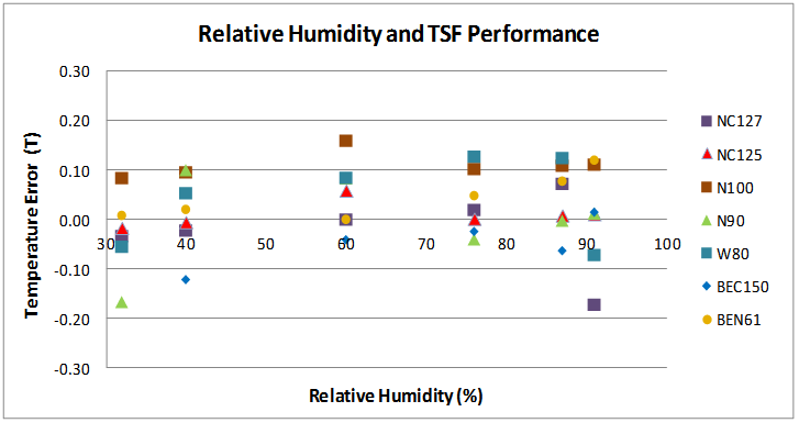
Figure 9 presents the effect of relative humidity on the relative increment of the TSF mass due to the increase in moisture. The relative mass of the TSF was calculated with 32% RH as the base value. It can be seen from Figure 9 that the relative mass of the TSF is directly related to the relative humidity in an exponential manner. This relationship was more pronounced at high humidity levels. At 65% RH, the average relative increment of mass of all TSF samples was found to be somewhere between 0.2 and 0.3% which is low in comparison to the documented moisture regain of polyester i.e. 0.4% at 20°C and 65% RH[18]. This error can be related to the initial RH value (32%) used to calculate the relative increment of the TSF mass. Once the completely dry weight of the TSF is known, the above-mentioned error may be reduced further.Figure 10 presents the effect of RH on the sensing performance of the TSF (in terms of error in temperature measurement). In order to understand and compare the effect of air humidity on TSF performance, resistance values of TSF acquired at various humidity levels were converted to the corresponding temperature values by making use of their respective calibration equation. The temperature values measured by the TSF were than compared with the temperature values noted by the Oregon Scientific Weather Station. The difference between the two temperature values was plotted against the relative humidity in Figure 10. It can be seen from the plot, that the relative humidity did not affect the TSF performance significantly. The temperature error was found to be in the range of ±0.15°C and random in nature. The error of ±0.15°C may be considered as acceptable considering the uncertainties associated with the: uniformity of the thermal environment, the measurement of temperature by the room hygrometer and the measurement of temperature by the TSF (calibration error and resistance measurement error).One of the possible reasons for the insignificant effect of humidity on the TSF performance may be related to the extremely low moisture regain of polyester. The moisture regain of cotton is 7% under standard conditions (20°C and 65% RH), which is much higher than polyester[18]. In the case of using cotton as a base material, the TSF might have experienced large measurement errors in different humidity environments. Because high moisture content would reduce the inter-wire insulation and leak the excitation current during measurement. This would measure artificially low resistance values and eventually show a lower temperature than in reality. From the above-mentioned results and discussion, it can be seen that choosing polyester over cotton[1] as the base material of the TSF was a superior decision. 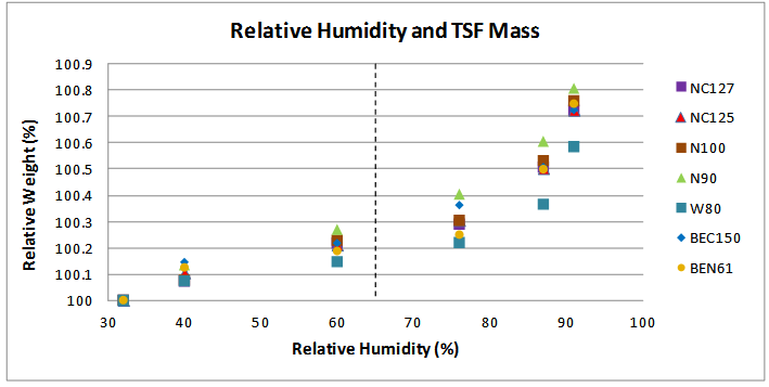 | Figure 9. Moisture Regain of TSF at various humidity levels |
 | Figure 10. Effect of Relative Humidity on TSF Performance |
4. Conclusions
This article reports the results of the effect of strain and humidity on the performance of Temperature Sensing Fabric (TSF) in the laboratory environment. The TSF is a double layer knitted structure with embedded fine metallic wire as sensing element. The working principle of the TSF is based on the fundamental tendency of the metal wire to vary its electrical resistance due to the change in its temperature. The TSF samples made of nickel, tungsten and copper wires in the form of bare and insulated form were tested in variety of strain and humidity environment. The TSF samples made of insulated sensing wire were found to be unaffected by strain-dependent resistance errors, it may thus be a better option to incorporate them in the practical environment, in preference to the TSF sample made with bare sensing wires. The moisture content of the TSF increased exponentially, with an increase of environmental humidity. The effect of relative humidity on TSF performance was found to be insignificant. The temperature error was random in nature and was well within the range of ±0.15°C. The TSF made with insulated wire as well as bare wire sensing elements could be used in a high humidity environment without any compromise in their sensing performance.
ACKNOWLEDGEMENTS
The authors would like to acknowledge the funding provided by the NED University of Engineering & Technology, Pakistan through the Higher Education Commission of Pakistan, to carry out this study.
References
| [1] | Husain, M.D., W.R. Kennon, and T. Dias, Design and Fabrication of Temperature Sensing Fabric. Journal of Industrial Textiles, 2013(doi: 10.1177/1528083713495249). |
| [2] | Husain, M.D. and W.R. Kennon, Preliminary Investigations into the Development of Textile Based Temperature Sensor for Healthcare Applications. Fibers, 2013. 1(1): p. 2-10. |
| [3] | Funnell, R., G. Koutoukidis, and K. Lawrence, Chapter 21 - Vital Signs, in Tabbner's nursing care: theory and practice. 2008, Churchill Livingstone: Australia. p. 251-274. |
| [4] | Ring, E.F.J., Progress in the measurement of human body temperature. Engineering in Medicine and Biology Magazine, IEEE, 1998. 17(4): p. 19-24. |
| [5] | Curone, D., et al. Smart Garments for Emergency Operators: Results of Laboratory and Field Tests. in 30th Annual International IEEE Engineering in Medicine and Biology Society (EMBS) Conference. 2008. Vancouver, British Columbia, Canada. |
| [6] | Derchak, P.A., K.L. Ostertag, and M.A. Coyle, LifeShirt® System as a monitor of heat stress and dehydration. 2004: VivoMetrics, Inc. Ventura, CA. |
| [7] | Noury, N., et al. VTAMN - A Smart Clothe for Ambulatory Remote Monitoring of Physiological Parameters and Activity. in 26th Annual International IEEE Engineering in Medicine and Biology Society (EMBS) Conference. 2004. San Francisco, California. |
| [8] | Pandian, P.S., et al., Smart Vest: Wearable multi-parameter remote physiological monitoring system. Medical Engineering & Physics, 2008. 30: p. 466–477. |
| [9] | De Rossi, D., A. Della Santa, and A. Mazzoldi, Dressware: wearable hardware. Materials Science and Engineering: C, 1999. 7(1): p. 31-35. |
| [10] | Locher, I., T. Kirstein, and G. Troester. Routing Methods Adapted to e-Textiles. in 37th International Symposium on Microelectronics (IMAPS 2004). 2004. Long Beach CA. |
| [11] | Ivo Locher, T. Kirstein, and G. Tr¨oster, Temperature Profile Estimation with Smart Textiles, in International Conference on Intelligent textiles, Smart clothing, Well-being, and Design. 2005: Tampere, Finland. |
| [12] | Ziegler, S. and M. Frydrysiak, Initial Research into the Structure and Working Conditions of Textile Thermocouples. FIBRES & TEXTILES in Eastern Europe, 2010. 17(6): p. 84-88. |
| [13] | Sibinski, M., M. Jakubowska, and M. Sloma, Flexible Temperature Sensors on Fibers. Sensors, 2010. 10(9): p. 7934-7946. |
| [14] | Parsons, K., Human thermal environments, in Human Thermal Environments. 2003, Taylor & Francis. p. 1-30. |
| [15] | Fourt, L. and N. Hollies, Factors involved in the study of clothing, in Clothing comfort and function. 1970, Taylor & Francis. p. 1-28. |
| [16] | Childs, P.R.N., Chapter 6 - Resistance Temperature Detectors, in Practical Temperature Measurement. 2001, Butterworth-Heinemann. p. 145-193. |
| [17] | Burns, J., 32.2 Resistive Thermometers, in The Measurement, Instrumentation, and Sensors: Handbook, J.-G. Webster, Editor. 1999, CRC Press LLC: USA. p. 32.13-32.24. |
| [18] | Sekhri, S., Chapter 8 - Synthetic and Inorganic Fibres, in Textbook of Fabric Science: Fundamentals to Finishing. 2011, PHI Learning Private Limited. p. 98-119. |
 Abstract
 Reference
 Full-Text PDF
 Full-text HTML