-
Paper Information
- Next Paper
- Paper Submission
-
Journal Information
- About This Journal
- Editorial Board
- Current Issue
- Archive
- Author Guidelines
- Contact Us
International Journal of Textile Science
p-ISSN: 2325-0119 e-ISSN: 2325-0100
2013; 2(4): 73-80
doi:10.5923/j.textile.20130204.01
Analyzing of the Woven Fabric Geometry on the Bending Rigidity Properties
 Abstract
 Reference
 Full-Text PDF
 Full-text HTML
Shafagh. D. Tohidi, Ali. A. A. Jeddi, H. Nosrati
Department of Textile Engineering, Amirkabir University of Technology (Tehran Polytechnic), Tehran, Iran
Correspondence to: Shafagh. D. Tohidi, Department of Textile Engineering, Amirkabir University of Technology (Tehran Polytechnic), Tehran, Iran.
| Email: |  |
Copyright © 2012 Scientific & Academic Publishing. All Rights Reserved.
The main content dealt with in this study is analyzing of the bending rigidity of woven fabrics as a function of fabric structure, fabric density (warp and weft spacing) and yarn counts to compare and approve the correspondence results of automatic cyclic bending tester made by Ajeli (Ajeli, Jeddi, Rastgo, & Gorga, 2009) at university of Amirkabir-Tehran with Shirley tester. And also we prepared microscopic pictures from cross section of the samples and achieved the aspect ratio of cross section of yarns in fabric structure (MATLAB software) in order to appropriate analysis of their mechanical behavior during implemented bending forces. For this purpose, five woven fabrics (plain, Twill 1/2, Twill 1/3, Twill 1/4, and Twill 1/5) are fabricated with three different densities (23, 29 and 35 warp per centimeter). The results show that the bending rigidity decreases with increasing of float yarns on both warp and weft directions. Furthermore, the value of bending rigidity on technical front side of the samples is less than technical back sides. Also there is difference between bending rigidity of weft and warp direction. There is a reasonable agreement between the measured values for both techniques.
Keywords: Woven Fabric, Fabric Structure, Bending Rigidity, Automatic Cyclic Bending Tester, Fabric Density, Shirley Tester
Cite this paper: Shafagh. D. Tohidi, Ali. A. A. Jeddi, H. Nosrati, Analyzing of the Woven Fabric Geometry on the Bending Rigidity Properties, International Journal of Textile Science, Vol. 2 No. 4, 2013, pp. 73-80. doi: 10.5923/j.textile.20130204.01.
Article Outline
1. Introduction
- Textile industry needs to be brought the texture process to higher technological stage which requires proper evaluating and simulating techniques to predict the future mechanical and physical characteristics of textiles (Ancutienė, Strazdienė, & Nesterova, 2010) (Luible & Magnenat - Thalmann, 2007). Analyzing the mechanical properties can enhance to determine the behavior of the fabrics during clothing exploitation. The mechanical properties of a fabric are depended to their geometry and also related to the formability and mechanical properties of the constituent yarns. Therefore, the study of fabric bending rigidity is very complicated because of the mechanical properties, arrangement and interaction between its constituent yarns (Fatahi & Yazdi, 2010) (Syerko, Comas-Cardona, & Binetruy, 2012). Fabric bending rigidity is one of the most important factors which has affect on handling and comfort of apparel; in 1930, the bending behavior has been explored quite extensively, beginning by Peirce (Peirce, 1930). On the other hand, bending rigidity is one of the most important properties of fabrics and is a key component in deciding fabric handle and drape. It is an important contributor to fabric’s formability (Allaoui, Hivet, Wendling, Soulat, & Chatel, 2011), buckling behavior (Dehkordi, Nosraty, Shokrieh, Minak, & Ghelli, 2010), wrinkle-resistance (Merati & Patir, 2011) and crease resistance (Merati & Patir, 2011). Knowledge of bending becomes particularly important when attempting the automation of processes involving out-of-planemanipulation. Abbott, et.al (G. A. V. Abbott, G.M., Gorsberg, P., & Leaf, 1973) (Abbott, N., Coplan, M., & Platt, 1960) proposed that because of the pressures at the crossover points, the yarn in the woven fabric is composed essentially of alternate rigid and flexible sections and it is assumed that the yarn lies in a straight line . Later, Grosberg, et.al (Grosberg, P., 1966) (Kedia., 1966) suggested that the bending behavior of woven fabrics is non-linear and is separated into two components: flexural rigidity and frictional resistance (Grosberg, 1966). It has been difficult to characterize the mechanisms of fabric bending. In 1971 a bending fabric model was proposed by Abbott, et.al (G. A. . Abbott, G.M., Gorsberg, P., & Leaf, 1971). They assumed that fabrics made from a large number of long and thin plates are such that the shear effect during bending can be neglected and therefore investigated the bending of a series of parallel plates. A theoretical analysis was used to obtain the predicted relationship between the applied couple and the curvature of the fabric, which contradicted the earlier work of Abbott in 1960 (Abbott, N., Coplan, M., & Platt, 1960). Grosberg and Abbott (Grosberg, P., & Swani, 1966) discussed the apparatus of Livesey and Owen (Livesey, R., & Owen, 1964) that bends the fabric in almost constant curvature. Also the importance of friction during the bending process and note that large errors are present if a linear bending approximation is used (Kedia., 1966). One of the initial models of fabric bending was done by Grosberg and Swani (Grosberg, P., & Swani, 1966) which modeled bending with an initial frictional restraint Mo that must be first overcome then a linear moment-curvature relationship. The Mo represents frictional resistance to bending at the yarn intersections. Once this frictional resistance is overcome, the yarns can be bent; hence the linear relationship once the initial resistance is overcome. Leaf et al (Leaf, G.A., Chen, Y., & Chen, 1993) considered a model by using strain energy and Costigliano’s theorem and developed a relationship between the flexural rigidity of a plain-woven fabric and the fabric and yarn parameters (Sun & Stylios, 2012). Ajeli et al. (Ajeli et al., 2009) investigated on the bending rigidity of warp-knitted fabrics as a function of knit structure (underlaps length), density (wale and course spacing) and yarn bending properties. The bending rigidity of the fabrics is measured by means of a Kawabata evaluation system and a prototype automatic cyclic bending tester. Results showed that the bending rigidity increases for the fabrics with a higher density and underlaps length of the front and back guide bars.Hence, the main aim of the present study is to clarify, in detail, the consequences of bending behavior of woven fabrics by consideration of increasing float yarns at fabric structure, fabric density (warp and weft spacing) and yarn counts by means of automatic cyclic bending tester made by Ajeli (Ajeli et al., 2009) and the validity of our approaches as matter of variation trend with the experimental data evaluated by Shirley tester.
2. Experimental Analysis
2.1. Preparing the Samples
- The research presented in this paper covers the practical verification of the monogram’s utility, as well as includes an analysis of the changes in the structure parameters at the moment of bending the three types of woven polyester continuous filament fabrics designed to show that difference between them which are caused by different float yarns inside of fabrics. All of the fabrics used the same polyester continuous filament warp of 3.5 tex. The weft differed in its linear density (7.8 tex, 11.5 tex, 16.7tex). The five forms of woven fabrics (plain, Twill 1/2, Twill 1/3, Twill 1/4, Twill 1/5) weaved. The density of yarns per centimeter considered constantly
 for warp yarns and
  and
and  for weft yarns.
2.2. Shirley Tester
- In most cases, authors who deal with the bending effect of textiles take advantage of Peirce’s theory as presented in the classic work that implemented by Pierce (Peirce, 1930) which contains the theoretical fundamentals on which most of today’s methods for the static measurement of bending rigidity are based. Bending rigidity of fabrics in warp and weft directions and also on technical back and front side of samples were measured by use of two different instruments, Shirley evaluation system (based on Pierce method) as can be seen in Figure 1 and an automatic cyclic bending tester (based on Livesey and Owen method). The amount of bending moment of the sample is determined and the relationship between the bending moment and the length of curvature is obtained as follow.
 | (1) |
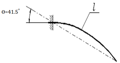 | Figure 1. principal of shirley tester (Livesey, R., & Owen, 1964) |
2.3. Automatic Cyclic Bending Tester
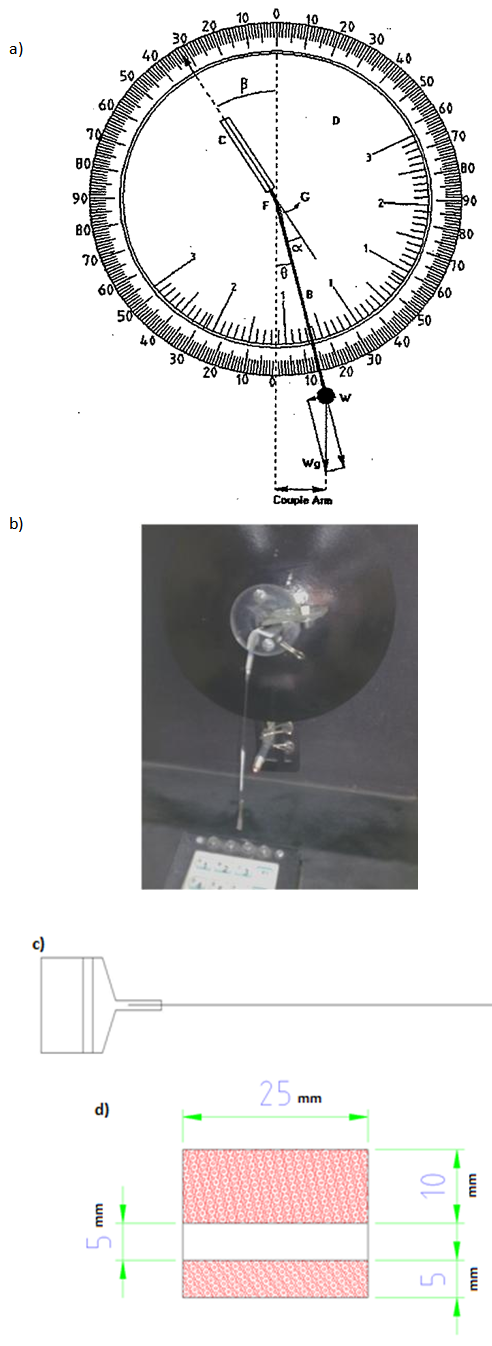 | Figure 2. a) cyclic bending tester made by Liversey et al (Livesey, R., & Owen, 1964) b) automatic cyclic bending tester made by Ajeli (Ajeli et al., 2009) c) the specimen pattern d) sample’s dimension |
 | (2) |
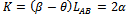 | (3) |
 | (4) |
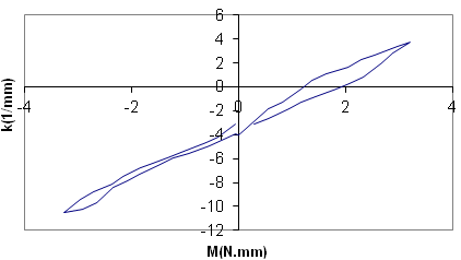 | Figure 3. A typical diagram of moment couples- curvature for samples |
2.4. Sample Preparation for Cross Section Observation
- For observing the cross section of fabric structures, we separated their samples into warp and weft directions and set of five samples such as plain through to Twill 1/5 in a cylinder frames are given in Figure 4. Thereafter a combination of polymeric resins such as Acryl, polyvinyl acetate and nitro cellulose injected into provided white cylindrical frames to fix the samples in the mold. After desiccating the embedded samples in resins, they were polished by series of particular abrasives (dense of 80, 100, 120, 400, 600, 1200, 1500 and 2000). Subsequently, fixed samples grinded by a polisher instrument. Ultimately, the fabric cross-section images achieved clearly under a reflective microscope.
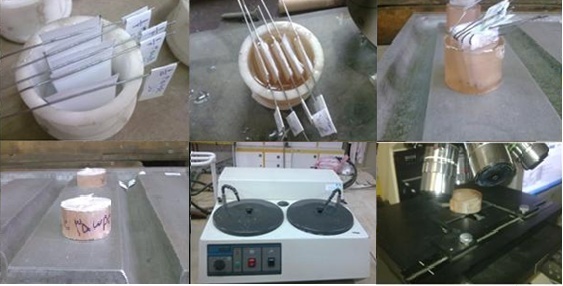 | Figure 4. Process of preparing of samples for taking microscopic images |
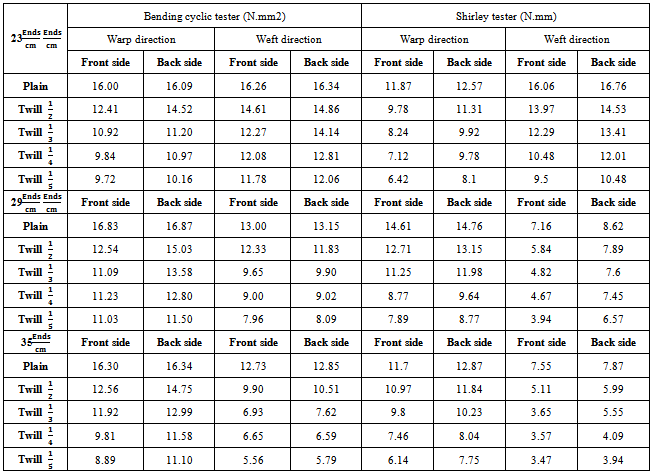
3. Results and Discussion
- The experimental data concern to values of bending rigidity of woven fabrics will found at the Table 1. As results show, float length has efficiency on bending rigidity of the woven fabrics. Increasing of float’s length infer to decline of bending rigidity’s value on both warp and weft directions. The Values of bending rigidity on weft direction for fabrics with density of
 are more than warp direction. Otherwise in the case of samples of
  and
and  , the mentioned trend would be reversed. Also the Bending rigidity values on technical back side of fabric are more than technical front side in all cases. In experimental analysis as it obvious, in the case of weft density of
  the bending rigidity values in weft direction is more than those in warp direction concerning to both sides. Otherwise this trend is reciprocal for
  ,
,  .
. 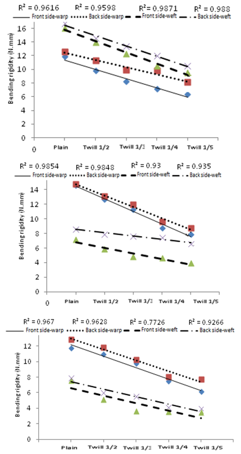 | Figure 5. a) Effect of rise of float length on bending rigidity for 23Ends/cm of Weft yarn b) Effect of rise of float length on bending rigidity for 29Ends/cm of Weft yarn c) Effect of rise of float length on bending rigidity for 35Ends/cm of Weft yarn (Shirley tester) |
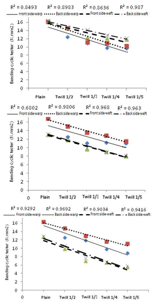 | Figure 6. a) Effect of rise of float length on bending rigidity for 23Ends/cm of Weft yarn b). Effect of rise of float length on bending rigidity for 29Ends/cm of Weft yarn c) Effect of rise of float length on bending rigidity for 35 Ends/cm of Weft yarn (automatic Bending cyclic tester) |
|
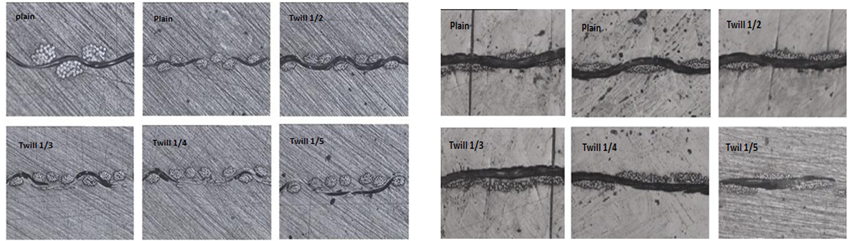 | Figure 7. a) Cross section of warp yarns on woven fabric’s structure b) Cross section of weft yarns on woven fabric’s structure |
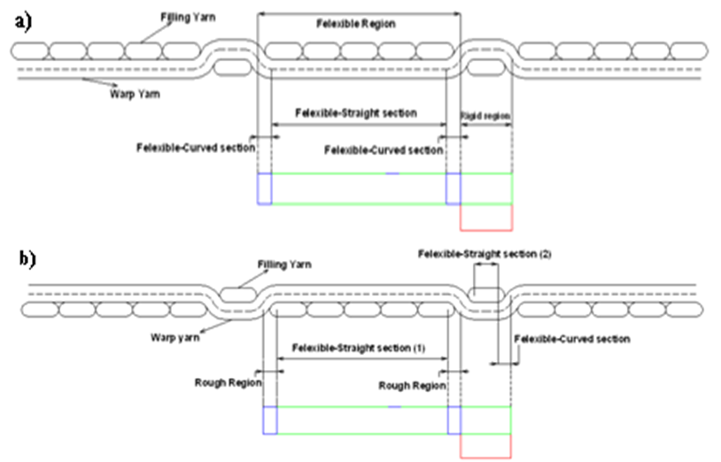 | Figure 8. a) Districting sections on simple model for twill 1/5 (Back side) b) Districting sections on simple model for twill 1/5 (Front side) |
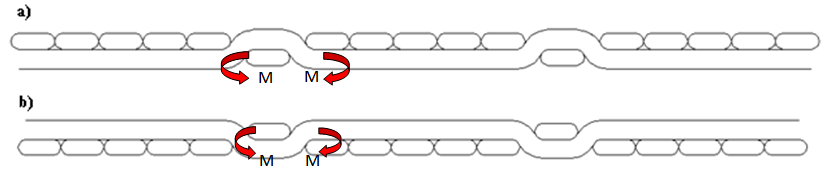 | Figure 9. a) Indicating imposed couples on intersection area for twill 1/5 (technical Back side) b) Indicating imposed couples on intersection area for twill 1/5 (technical Front side) |
4. Conclusions
- In this study, the relationship between the bending rigidity of woven fabrics discussed. Moreover, we demonstrated that the results from the Shirley tester and automatic cyclic bending apparatus correlated well together. As results show, float length has efficiency on bending rigidity. Increasing of float’s length infer to decline of bending rigidity’s value on both warp and weft directions. The Values of bending rigidity on back/front side of fabric in weft direction for fabrics with density of
 are more than warp direction. Otherwise about samples of
  and
and  , the mentioned trend would be reversed. Also the Bending rigidity values on technical back side of fabric is more than front side of fabrics in all cases which meaningful explanations were considered. There is difference between bending rigidity in weft and warp direction. Eventually a reasonable agreement between the measured values for both techniques is inevitable .
ACKNOWLEDGEMENTS
- The authors would like to acknowledge the support of Amirkabir University of Technology for department of Textile for use of automatic cyclic bending tester and the Textile Protection and department of Mine Engineering for capturing microscopic images from cross section of woven fabrics. We also especial thank to JACKOB MUELLER Company for providing the experimental samples.