-
Paper Information
- Previous Paper
- Paper Submission
-
Journal Information
- About This Journal
- Editorial Board
- Current Issue
- Archive
- Author Guidelines
- Contact Us
International Journal of Sports Science
p-ISSN: 2169-8759 e-ISSN: 2169-8791
2016; 6(6): 249-256
doi:10.5923/j.sports.20160606.08

Models and Modelling of Dynamic Moments of Inertia of Human Body
 Abstract
 Reference
 Full-Text PDF
 Full-text HTML
Miroslav Dodig
Independent Researcher, University of Rijeka, Croatia
Correspondence to: Miroslav Dodig, Independent Researcher, University of Rijeka, Croatia.
| Email: |  |
Copyright © 2016 Scientific & Academic Publishing. All Rights Reserved.
This work is licensed under the Creative Commons Attribution International License (CC BY).
http://creativecommons.org/licenses/by/4.0/

From the biomechanical standpoint, the dynamic moment of inertia in the kinetic structure plays an important role; especially when it comes to executing movement in open and closed kinetic chains. The main task of the analysis is focused on models and modelling of dynamic moment of inertia of specific body parts as well as the entire body. Some important definitions of dynamic moments of inertia have been pointed out, based on the approximate geometric shapes of specific segments and anthopometric sizes. For each body configuration, solid body parts of simple geometric shapes (circular cylinders, sticks and ellipsoids) were used. The suggested model for the head, neck, and fist was modelled with the help of the ellipsoid; the model for the forearm, upper arm, lower leg, upper leg was modelled with the help of cylinders; and for the torso and foot with the help of the parallelepiped. By knowing the sequential body configuration and the time-shift, it is possible to calculate the dynamic moment of inertia. The suggested models for body, arm, and leg were those in which the potential configurations and the influential proportions of distribution of mass were analysed. The choosing of the optimal models for modelling dynamic moments of inertia was described, and those models were presented as the best approximation of the dynamic moment of inertia in the dynamic sense.
Keywords: Biomechanics, Dynamic moment of inertia, Models and modelling, Kinetic chains (Specific body parts and the entire body)
Cite this paper: Miroslav Dodig, Models and Modelling of Dynamic Moments of Inertia of Human Body, International Journal of Sports Science, Vol. 6 No. 6, 2016, pp. 249-256. doi: 10.5923/j.sports.20160606.08.
Article Outline
1. Problem
- As the patterns of motion of all material bodies of smaller or larger capacity in space are researched, so are the patterns of motion of every live. The body of the living man is viewed as any given material body that is subject to the influence of all forces that govern in the narrow sphere of the Earth’s impact. On the other hand, the body of man is viewed as not only a material object, but as a defined lever system. Every level within man has a certain place in the whole system of levers. As soon as one lever can, in relation to the remaining part of the system, arbitrarily change its place within the system, the execution of a certain motion becomes that much more complex. On the third hand, man’s locomotor system, aside from the articular levers, possesses its own impetus, a momentum presented by the muscular contractile ability. But even this system of internal forces cannot be arbitrarily moved around and can be increased only to a certain extent, thus the determined motion of the system is even more complex. The kinetic assembly makes up a certain number of discreet working units and a system of rules for their combinatorics (subordination, autonomy, synergy and antagonism) as well as integration within the kinetic structure, thus forming kinetic chains. From a biomechanical point of view, the dynamic moment of inertia in the kinetic structure plays an important role, especially during execution of motion within open and closed kinetic chains. By understanding the sequential configuration of the body and the time shift it is possible to the dynamic moment of inertia. The basic task of studying is directed at the models and modelling of the dynamic moment of inertia of certain body parts as well as the whole body. While the primary goal is to suggest models based on which a dynamic moment of inertia within kinetic structures of the open and closed kinetic chain can be modelled on.1In classic mechanics, which represents an entirety, three basic branches can be discerned: statics, kinematics and dynamics. Statics studies static equilibrium and causes of equilibrium and inactivity of material bodies. Kinematics studies motion of geometrical bodies neglecting the material body, but introduces a new basic concept – time and keeps track of time intervals in which certain motion occurs. The dynamic includes elements of statics as well as elements of kinematics, i.e. studies motion of material bodies in a designated time frame and under specific circumstances - force. We encounter a new concept in dynamics, and that is mass. As dimensions and time are expressed with numbers, thus the materiality of a body is expressed via mass. Mass is always a positive number, while the unit for mass is one gram of mass [14]. Instatics, force is defines as a vector, that is, as a cause that can change the state of equilibrium of a body or its motion. In statics, force is the primary element and it does not take into account the materialityof the body itself. Kinetic energy or the energy of the body in motion, is measured by an action that the body can carry out overcoming external forces, before it brings itself in the state of inaction. Body mass m and velocity v have the following kinetic energy: T= mv2/2. It is clear that the fundamental kinetic patterns of motion are based on mechanical patterns. Introducing the basic units of length, time and mass, basic concepts about spatial forms, materiality of body and about time are expressed, where stated changes are taking place. In dynamics, force is not the primary element, it is defined with the help of fundamental physical values (space, mass – time). The definition of force in dynamic was given by Newton (Philosophiae naturalis principia mathematika, London, 1687), in the form of three renowned maxims.One part of the human body cannot arbitrarily move in all directions in relation to the other body parts due to the specific build of the osteoarticular movement system [6, 8]. This same body part cannot be started with an arbitrary strength of muscles, as the muscle cannot take action from every angle. In addition, the potential of the agonist muscle is not the same in all directions, thus a given body part cannot initiate identical values by force in various directions. This mobile body part moves around in its natural environment, and is influenced by external forces. In order to find the possibility for initiating certain kinetic chains (body parts), a biomechanical analysis of the kinetic structure that includes specific kinetic chains needs to be conducted. Complex motion is comprised of a series of spatial, timely executed motions and is determined through anatomical – mechanical analysis [9, 10]. During the anatomical – mechanical analysis of motion, findings from anatomy (static and dynamic anatomy) as well as from mechanics of living beings and biomechanics are put to use [4]. Dynamic behaviour of kinetic chains requires a comprehension of the distribution of its segmential masses and with that dynamic moments of inertia, what was, in effect, the primary goal of this study. Motion of the human body is possible in dynamic and static conditions. For defining the dynamic moment of the inertia of body movement it is necessary to have an understanding of distribution of mass in segments of specific open and closed kinetic chains [1].
2. Discussion
2.1. Models and Modelling of Dynamic Moments of Inertia of Body
- The body model is based on a mechanical system with 16 absolutely firm bodies that are connected by joints. The geometric form of joint surfaces, bone levers and muscle force, among other things, determines the regularity and pattern of motion in working units of the kinetic system and the whole kinetic chain. The kinetic chains are viewed from a perspective of kinetics as a sequence of activating and shifting certain segments or the whole body within a kinetic structure. The more kinetic chains within a kinetic structure is active, thus the kinetic structure is more complex [5, 7]. The spatial and temporal organization of the majority of kinetic chains is complex. Complex kinetic structures develop in several joints under the influence of an increasing number of muscle groups or under the influence of an entire muscle system. Upon complex motion in the kinetic system, kinetic chains and kinetic muscle convolutions are educated within the kinetic system. Kinetic muscle convolutions are educated by agonist, antagonist and synergist muscles, which via bones and fibrosis formations continue one into the other. Kinetic chains in the kinetic system are even and can be long or short, open or closed (depending whether the limb ends are free or attached to an object). While doing so, it is good to bear in mind that the kinetic chain can be presented within the context of anthropometric, anatomical – functional elements in the process of execution of certain kinetic structures [16]. The dynamic moments of inertia within a human body change with the shift of the relative position of the body although they are constant, considering their own central axes, regardless of the position of the body. This ensures the possibility that the moment of inertia of the body is determined via their own moments of inertia of certain body parts and their summation into a whole (Steiner’s Rule on entirety). For determining the dynamic moment of inertia of body parts, it is necessary to model the body parts in accordance with the adequate geometrical bodies [17]. Related dimensions and masses are determined with the help of knowledge about harmonious division of mass and dimensions of human body parts. Dynamic behaviour and man’s motion is in proportion to the body’s weight, while having knowledge about division of segmenting masses as well as dynamic moments of inertia, is necessary for its comprehension [3, 19]. While studying the position of the kinetic chain various biomechanical analysis are used in the formulation of motion of any given general model. (picture 1).
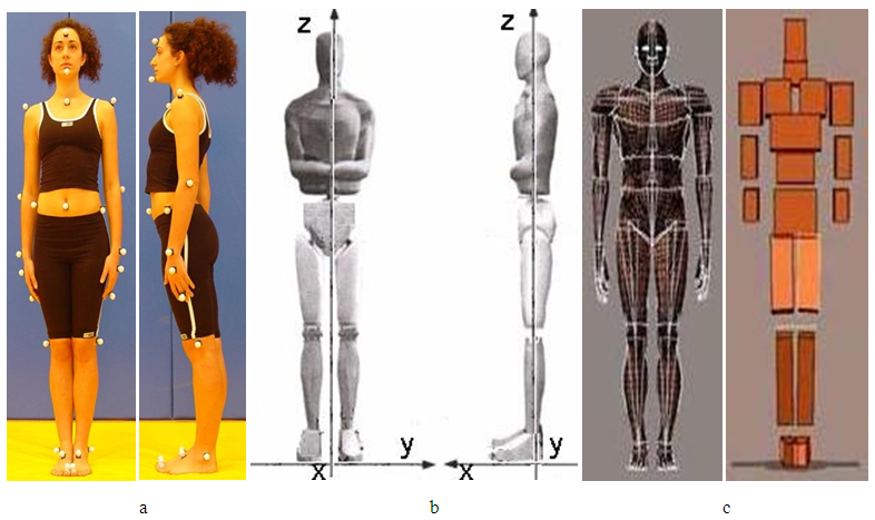 | Picture 1. Models of the human body that can be used in analyses of positions of kinetic chains for calculating the dynamic moment of inertia are displayed: a) model with markers b) model with coordinates i c) model with body segments |
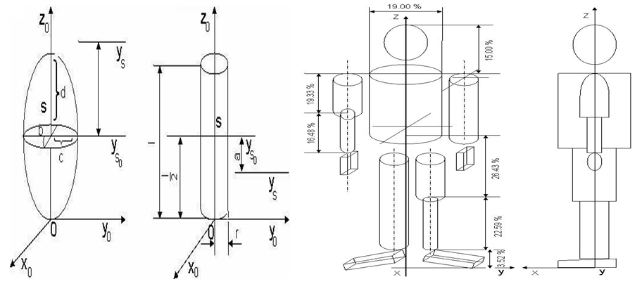 | Picture 2. Displayed is a model of simplified segments (eliptic cylinder, ellipsoid and circular cylinder) and a model of simplified segments of the human body which is comprised of approximate geometrical shapes |
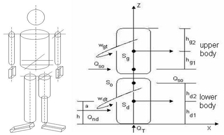 | Picture 3. Displayed is a model of simplified segments of the human body that is comprised of approximate geometrical shapes and simplified segments of the upper and lower body parts with accompanying signs |
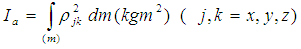 Position of
  - distance of segment from inertia axis.Dynamic moments of inertia can be determined through simple linear transformations for any given group of orthogonal axes, and represent tensor values of the second order. Based on the abovementioned expression it is clear that integration will, over the span of the entire mass, serve as an example of equal density over the whole segment. For determining the mass and centres of mass segments of the body, a regressive equation is frequently used. For the dynamic body model, the law of quantity of motion is applied, what represents a somewhat complex mathematical process that takes the following into account: force in motion, velocity of the upper and lower body parts and translational and rotational requirements. These calculations use dimensionless coefficients (two of them) that are dependent on the size and schedule of the model of the upper and lower body parts. When they are determined, forces of motion and velocity are calculated with them, after which the problem is yet again reduced to studying the motion of particles. Using the simplified form of calculation for displaying the value of influence of distribution on mass and dimensions of the human body, and potential behaviour in terms of motion. Dimensionless coefficients are the following functions:
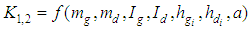
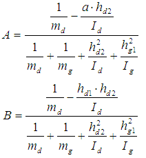 Coefficients key:md – mass of lower body mg – mass upper body h – total body height hd – height of lower body hg – height of upper bodyIt is clear that coefficients depend on the dynamic anthropometer of subjects and represent anthropodynamic coefficients. If distribution of mass and height on the upper and lower body is carried out, dynamic moments of inertia in view of the mass centres can be calculated with the following expression:
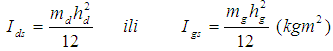 It is visible that coefficient B is dependent upon the value of masses and their distribution in terms of the upper and lower body part. Coefficient A is dependent on the point of motion position i.e. the height h.
2.2. Models and Modelling of Dynamic Moments of Inertia of Arm
- The arm is biomechanically made from segments that constitute an open and kinetic chain that is possible to mold as a simple cylindrical or prismatic body. It is possible to determine axial dynamic moments of inertia with a strong coordination system. It is possible to determine the dynamic moment of inertia with simple linear transformations for any given group of ortogonal axes, thus tensor values are second rate. An integration over the whole mass that is of equal density through the whole volume is carried out on the basis of this. Based on obtained anthopometric measures, while using a regressive equation, masses and centres of mass of arm segments can be determined. Determining the dynamic model of the hand pursuant to the definition of components of the inertia tensor for arm analysis, knowledge of the cutoff plane function is necessary. We observe the hand as a system of poles and parallelepipeds (picture 4).
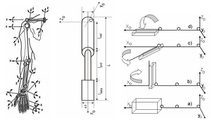 | Picture 4. The arm is displayed as an open kinetic chain with possible directions of motion and the dynamic arm model with various positions of the fist (a,b,c,d) projected into the coordinate system |
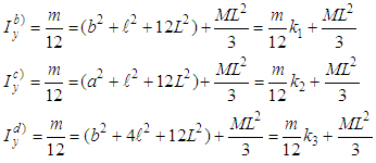 where:m - mass of fist a,b - horizontal dimensions of the parallelepiped model of fistl - length of parallelepiped model of fist M - mass of forearm and upper arm L - length of forearms and upper arms With a calculation in the equation for the group of percentiles factors ki (k1, k2, k3.) are obtained and ultimately moments of inertia
 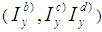 .Observing the arm as a uniform pole of the following length (L+l) and mass (m + M), the moment of inertia will be:
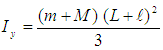 However, if we concentrate certain masses in the centre of mass parts, the moment of inertia will be:
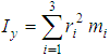 Observing the arm as a uniform pole of L length (closed fist), the moment of inertia will be:
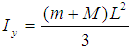 Calculating the mass value, the mass centre as well as the dynamic moment of inertia of an extended arm where the longitudeness of the whole arm is varied along the whole length (key : (l) – total arm length, (c) – distance of fist centre from the shoulder joint and (L) – length of arm with closed fist). Thus, an outsretched fist obtained with a parallelepiped orientation of the fist will not have a significant impact on the value of the dynamic moment of inertia, as the coordinate system at the centre of the shoulder joint has. Thus, factors k1, k2 and k3 change by turning within the shoulder joint, and at the same time total moments of the inertia of the arm. On the other hand, if the total arm length is taken into account (L + l), along with the total arm mass, we calculate the moment of inertia that significantly differs from the previous ones. The difference occurs in the kinetic chain where masses are concentrated in the centre. As the closest models b, c, d according to values, the model of the uniform pole of the whole arm appears, the length of which extends from the shoulder joint to the end of the closed fist.
2.3. Models and Modelling of Dynamic Moments of Inertia of Leg
- The selection of the leg model in dynamic anthropometry uses the anatomical analysis. The selection of the dynamic model is based on the first approximation of the leg i.e. the model takes it as a system comprised of two cylindrical poles (upper and lower leg) and the eccentric parallelepipe (foot). The leg is set in the coordinate system, setting its starting point in the centre of the femur, where the axes are selected (picture 5).
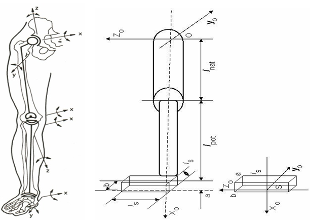 | Picture 5. A leg is displayed as a closed kinetic chain with possible directions of motion and the dynamic model of the leg and foot, projected into the coordinate system |
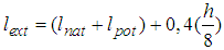 where h is the body’s height.Through application of calculated anthropomeasures for all percentile groups, it is possible to calculate the moment of inertia on the basis of the above description of the selected model, based on the equation that in its general state reads as follows
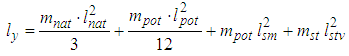 here mnat - mass of upper leg (kg)mpot - mass of shin (kg)mst - mass of foot (kg)lnat - length of upper leg (m)lpot - length of shin (m)lsm - distance of mass centre of shin from the centre of the hip joint (m)lstv - real mechanical leg length on the example of an extended leg, the last member fall out of the above equation, and in its place comes
 where
where 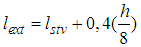 The behaviour of the value of the moment of inertia considering the axis yo, which is at the same time the rotation axis, for this purpose the axes for the leg and foot project into the coordinate system.The moments of inertia for the axes xs, zs, ys parallelepipes that go through the centre S and the axis y which is parallel with the axis ys read as follows:
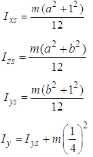 It is necessary to select such dimensions of parallelepipes so that this volume can join the foot. On application of the parallel shift of axis theorem or the so-called Steiner’s Rule, moments of inertia are determined taking into account that the axes 0xo, 0yo i 0zo will from hereon be:
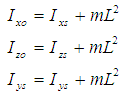 Where the “L“ distance between the axes xs, ys, zs and the axes xo, yo, zo,. Thus, the values of mL2 should be added before the calculated moment of inertia. The conclusion that imposes itself is that the selected model of parallelepipes as a foot surrogate is unnecessary as it is relatively small in relation to the moment of inertia as possessed by the mass itself taking the rotational axis into account. At the same time, this means that any kind of foot rotation around the axis xo for the calculation is negligible, so it is all the same as far as the moment of inertia is concerned, whether the foot stands in the direction of the axis z or it is at an angle
  . However, it is to be expected that the value of the moment of inertia considering that the same axis varies as regarding different models, wheras a model that fits the real state must be selected. Thus, the model of the anthropometric dynamic moment of inertion for the flexed leg must, upon calculation, separate the shin from the upper leg. However, the length of the leg changes when the leg is extended (the pronated foot), and the tentacle of the foot mass increases in realtion to the axis y thus in this way the last member of the expression
  is increased. Upon calculation certain problems occur in the application of the values in ergonomic practice as the variations of these anthropomeasures are joined with biomechanical models, which have different definitions and conditions. If the kinetic compoment (i.e. the kinematic and dynamic side of the problem) is added to that, then a certain difference occurs even in the simpler models that can always be disregarded.
 3. Conclusions
- In biomechanical analysis of open and closed kinetic chains, a significant place belongs to contemporary methods of analysis of dynamic moments of inertia. It is therefore, important to be familiar with the dynamic moment of inertia of specific chains, or of certain number of kinetic chains. Hence the idea of geometric and dynamic anthropometers for the calculation of main dynamic moments of inertia for specific body parts as well as the entire body. For each body configuration solid body parts of simple geometric shapes (circular cylinders, sticks and ellipsoids) were used. The suggested model for the head, neck, and fist was modelled with the help of the ellipsoid; the model for the forearm, upper arm, lower leg, upper leg was modelled with the help of cylinders; and for the torso and foot with the help of the parallelepiped. By knowing the sequential body configuration and the time-shift, it is possible to calculate the dynamic moment of inertia. The suggested models for body, arm, and leg were those in which the potential configurations and the influential proportions of distribution of mass were analysed. The choosing of the optimal models for modelling dynamic moments of inertia was described, and those models were presented as the best approximation of the dynamic moment of inertia in the dynamic sense. Simple models that enable modelling of internal and external dynamic anthropometers for specific body parts as well as the entire body were presented. Based on that, models for modelling dynamic moments of inertia for specific kinetic chains were presented.
Note
- The presented material was used in the project - Suit for training process, the University of Rijeka - Science and Technology Park. The State Office for Intellectual ownerships R. Croatian admitted (15.03. 2013) Consensual patent number PK20130227. which is located in the Technology Transfer Office, Slavka Krautzeka 83A, Rijeka E-mail: utt@uniri.hr