-
Paper Information
- Next Paper
- Previous Paper
- Paper Submission
-
Journal Information
- About This Journal
- Editorial Board
- Current Issue
- Archive
- Author Guidelines
- Contact Us
Software Engineering
p-ISSN: 2162-934X e-ISSN: 2162-8408
2012; 2(4): 129-137
doi: 10.5923/j.se.20120204.06
Distributed Real Time PCM System, UML Design and Development with Embedded Programming
 Abstract
 Reference
 Full-Text PDF
 Full-Text HTML
Zeeshan Ahmed
University of Wuerzburg, Germany
Correspondence to: Zeeshan Ahmed , University of Wuerzburg, Germany.
| Email: |  |
Copyright © 2012 Scientific & Academic Publishing. All Rights Reserved.
This manuscript presents research conducted towards the proposition, design and implementation of an intranet hardware control and data management system. Solving the problem of automatically extracting print based information from each user system of a workgroup and managing that in an enterprise database management system, a new approach i.e. PCM System is proposed in this manuscript. PCM System is a platform independent distributed real time software application. It uses the concepts of system and embedded programming and implements a thread that provides a dynamic print look up service. The successfully achieved goal of this research was limited up to the retrieval of deployed plotter and printer’s information from user system. Furthermore at user given print request, system snatches, transfers and saves processed information in the database with the help of an intermediate server system. Going into the details of the newly proposed approach, this manuscript portrays the network structure, provides some UML descriptions of implemented designs (including use case, data flow, flow chart, system sequence, class and component diagrams) and presents a graphical user interface of the application. Validating the potential of implemented approach, a case study is also described based on a real time scenario.
Keywords: Distributed System, Real Time System, Embedded Programming, System Programming, Print Control, Hardware, Unified Modeling Language (UML)
Cite this paper: Zeeshan Ahmed , "Distributed Real Time PCM System, UML Design and Development with Embedded Programming", Software Engineering, Vol. 2 No. 4, 2012, pp. 129-137. doi: 10.5923/j.se.20120204.06.
Article Outline
1. Introduction
- Designing and implementing a distributed real time embedded system involving any kind of software and hardware is always a challenging task for the designers and developers. To overcome the problems in resolving the challenge of creating an appropriate hardware oriented software application capable of monitoring plugged printing devices and automatically extracting print based information from each user system of a workgroup, and managing that using a database management system, a methodical research is conducted mainly in the fields of system programming[1], embedded systems[6], printer and plotter controlling[2] and network programming[3],[4].System programming is also renowned as the low level programming methodology, the branch of software programming capable of providing services to control hardware devices. Using system programming concepts a programmer not only can control the basic internal hardware components of a computer (e.g. ports, display, memory etc.)[24] but can also direct plugged devices (e.g. keyboard, mouse, printers, universal serial bus etc) [35],[36]. Old, most recommended, commonly used system and embedded programming languages are Assembly[5] and C languages[6]. Furthermore, now days it’s also possible to do system programming at some level using object oriented programming languages as well e.g. C++[6], Java[7] and C#[8] etc.The focus of this research and development is first to solve the problem of extracting user’s print based information, then save the extracted information into a database accessible to the administrator for further record keeping and data manipulation. In an intranet workgroup environment where multiple users are connected to one or many print servers can send multiple print requests to associated printers (including plotters). Many useful commercial print management software applications do exists e.g. PaperCut[19], CZ Print Job Tracker[20], A.N.D. Pcounter[21], Cyclope Print Management Software[22], HP Web Jetadmin software[23], ObjectPrint[32], papercut[33] etc., putting values in taking advantage in tracking print records to reduce print costs and increase environmental impact. There is no such (freely available open source) solution available which can help in having the information (e.g. user name, used printer, number of pages printed, job requested, time, date etc.) about all sent print requests by all users along with explicitly provided dynamic real time product line architecture based relational data management system, offered, claiming to provide efficient data management of printed records in intranet workgroup environment.The manuscript is organized as follows: going from a more general overview, section 2 describes the implemented PCM System. Section 3 presents UML[13][10] designs including Use Case (Section 3.1), Data Flow (Section 3.2), Internal Work Flow (Section 3.3), System Sequence (Section 3.4), Class (Section 3.5) and Component Diagrams (Section 3.6). Section 4 validates the potential of PCM System with the help of a case study of a real time scenario. Section 5 concludes the manuscript.
2. PCM System
- Targeting the defined problem of automatically extracting print based information from each user system of a workgroup and managing that using a database management system, and following the concepts of system programming[1], printer and plotter controlling[2] and network programming[3],[4], proposed a new approach i.e. Printer Control and Management (PCM) System.PCM System is capable of working in any (existing) implemented network structure, providing current view of connected print devices, monitoring printing, providing print history and notifying printing.
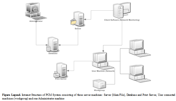 | Figure 1. PCM System; Intranet Structure |
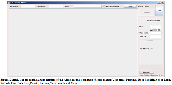 | Figure 2. PCM System; Admin Module |
3. PCM System UML Descriptions
- The most direct method of designing architectures of software applications is Unified Modelling Language (UML), as it plays important role in standardizing way of designing by creating different abstract models. It is capable of facilitating software engineers with stand alone and interconnected semiformal (Meta) design views for modelling software architectures[13]. Here software designs are created using UML principles to have better understanding of PCM System in terms of its implementation, usage and working, Designed UML diagrams are describing over all feature based functionality, user accessibility, experimental data flow, internal system work flow, system sequence, involved component’s integration and source code structure. This manuscript presents following PCM System UML designs: Use Case, Data Flow, Internal Work Flow, System Sequence, Class and Component Diagrams.
3.1. Use Case
- Use case is the specific textual and visual method of presenting software application’s functionalities comprising all ways of user system interactions[14], consisting of two main symbolic notations i.e. Actor and Activities. In most of the cases actor is either user or system itself as a remote actor and activity is the event triggered by the system in response to the request by actor for some action. The designed use case diagram (Figure 3) of PCM System describes the user system interaction (Table 2) which consists of a User (actor), four direct activities: Login System, Open Document, Print Request and Printed Document, and two indirect associated activities: Printer/Plotter and Print Information. The use case of PCM System explains the basic flow of user system interaction starting with the execution of software application. User logins successfully, opens any text or graphic document (e.g. Microsoft word, power point, excel sheet, notepad, image file, PDF etc.) and send print request to the print server for printing. In return user will get printed document and print information status will be extracted and saved.
|
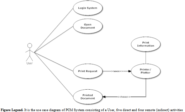 | Figure 3. PCM System; Use Case |
3.2. Data Flow Diagram
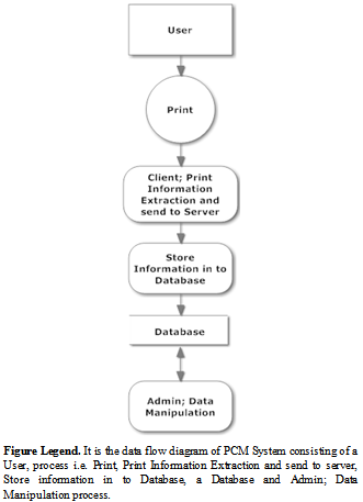 | Figure 4. PCM System; Data Flow Diagram |
3.3. Flow Chart
- Flow chart is the step by step visual representation of defined interlinked processes (operations) in a software application[16], categorized in different shaped boxes representing different kinds of operations connected by directional and unidirectional (associated) arrows. The flow chart of PCM System starts with the user login in the system connected to the workgroup of the intranet. User is supposed to open (one or multiple) document file(s) and prepare request for the printing using plugged printers. In case of unsuccessful printing, control will be sent back to File and notification will be sent to the user. If printing will be successful then print information (data packets) will be sent to the main server of the work group. In case of unsuccessful data packet transfer control will be sent back to the client module and in case of successful data packet transfer information will be stored in the database (Figure 5) and system will be ready for next transaction.
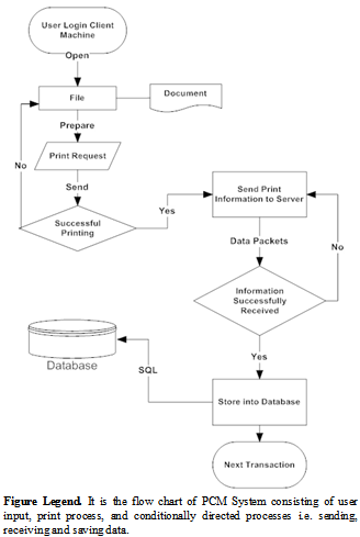 | Figure 5. PCM System; Flow Chart |
3.4. System Sequence Diagram
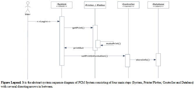 | Figure 6. PCM System; System Sequence Diagram |
3.5. Component Diagram
- Component diagram is the visual presentation of assembled constituents representing structural relationship between service provider and consumer[10]. It allows the designer to confirm system's functionality to be implemented in the form of components using internal and third party services (e.g. programming languages, libraries, executables, application programming interfaces, frameworks etc.) in terms of nature and behaviour.
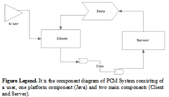 | Figure 7. PCM System; Component Diagram |
3.6. Class Diagram
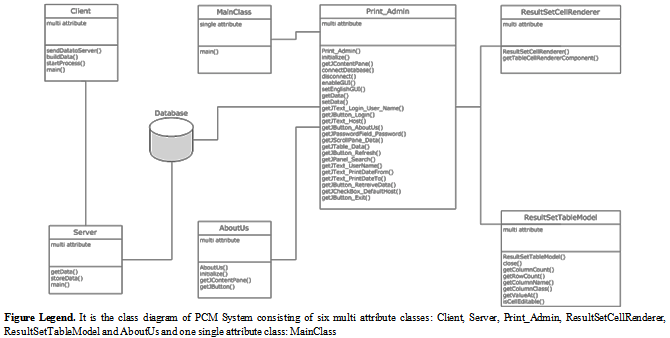
- Class diagram is the static representation of relationships between defined classes for the development of a software application[11],[12]. The source code development of PCM System is divided into seven main classes (Figure 8) i.e. Client, Server, MainClass, Print_Admin,ResultSetCellRenderer, ResultSetTableModel and AboutUs.1. Client is a multi attribute class with four methods: sendDatatoServer, buildData, startProcess and main, created in package PrintClient. “sendDatatoServer” is the method to connect and send data to server, “buildData” is the method to build data packets, “startProcess” start performing jobs and “main” executes client module. 2. Server is a multi attribute class with three methods: getData, storeData and main, , created in package PrintServer. “getData” is the method to receive data from client, “storeData” is the method to send data to database server to store and “main” executes client module.3. Main is a single attribute class with one method “main” to execute Amdin module, created in package PrintAdmin.4. Print_Admin is a multi attribute class with twenty four methods: initialize, getJContentPane, connectDatabase, disconnect, enableGUI, setEnglishGUI, getData, setData, get JText_Login_User_Name, get JButton_Login, get JText_Host, get JButton_AboutUs, get JPasswordField_Password, get JScrollPane_Data, get JTable_Data, getJButton_Refresh, get JPanel_Search, get JText_UserName, getJText_PrintDateTo, get JButton_RetreiveData, getJCheckBox_DefaultHost and get JButton_Exit, created in package PrintAdmin. “Initialize” initializes GUI components, “getJContentPane” initializes content pane component, “connectDatabase” establishes database connection, “disconnect” disengage established database connection, “enableGUI” enables or disables GUI, “setEnglishGUI” converts control text in German language, “getData” retrives result from database, “setData” sets record set, “getJText_Login_User_Name” initializes text control for user login information, “getJButton_Login” initializes login button, “getJText_Host” initializes text control for host information, “getJButton_AboutUs” initializes button for giving version information, “getJPasswordField_Password” initializes password text field, “getJScrollPane_Data” initializes scroll pane, “getJTable_Data” initializes table, “getJButton_Refresh” initializes button to refresh database connection, “getJPanel_Search” initializes search panel, “getJText_UserName” initializes user name text field, “getJText_PrintDateTo” initializes field to take date, “getJButton_RetreiveData” initializes button to retrieve searched data, “getJCheckBox_DefaultHost” initializes check box to set default host getJButton_Exit initializes exit button.5. ResultSetCellRenderer is a multi attribute class with two methods: ResultSetCellRenderer and getTableCellRendererComponent. ResultSetCellRenderer is the constructor and getTableCellRendererComponent is the method to render components.6. ResultSetTableModel is a multi attribute class with eight methods: ResultSetTableModel, close, getColumnCount, getRowCount, getColumnName, getColumnClass, getValueAt and isCellEditable, created in package PrintAdmin. "ResultSetTableModel" is the constructor creates a TableModel from a ResultSet, "close" closes the ResultSet, "getColumnCount" returns the number of columns in table, "getRowCount" returns the number of rows in table, "getColumnName" returns columns names from the ResultSetMetaData, "getColumnClass" specifies the data type for each column of table, "getValueAt" returns the value at each cell of the table and "isCellEditable" returns the status of table, whether it is editable or not.7. AboutUs is a multi attribute class with four methods: AboutUs, Initialize, getJContentPane and getJButton, created in package PrintAdmin. "AboutUs" is the constructor, "initialize" sets the GUI, "getJContentPane" initializes content pane and "getJButton" initializes buttons.
4. PCM System Validation
- PCM System was deployed in a medium sized departmental workgroup, intranet consisting of around 50 user systems. Briefly describing the network structure, user systems are interlinked with a main server system, a database server system and three printers via printer server system. The whole case study consists of following ten steps:1. The database was created using SQL scripts and made available at database server of the workgroup. Then the Admin module was installed and executed in the administrator system of the workgroup. Administrator then connected PCM System’s admin module to the database server (with valid login name, password and host address).2. The PCM System’s server module was installed and executed in the main server of the workgroup. When the server module started functioning, it immediately sent request to connect to the database server, and soon after successful connection it started looking for client requests.3. The PCM System’s client module was installed and executed in all client systems of the workgroup. When the client module was executed, at first it snatched all information based on plugged printers (via print server): Lexmark C734 XL, HP LaserJet 4250 PCL 6, HP LaserJet 4100 Series PCL, Adobe PDF, Microsoft Office Document Image Writer and Microsoft XPS Document Writer. (Figure 9)4. User “zea77ir” successfully logged-in a user system of the work group. Opened a document and sent a print request using printer “Adobe PDF”. (Figure 9)5. The print information was immediately extracted and sent by the client module to the main server system (Figure 9), where server module was already running, waiting and ready to facilitate client request (Figure 10). 6. Client request for connection was received at server module sent by the client module and later after the successful authentication, server successfully received data packets. 7. Then server automatically organized and sent received print information to the database server for storage and maintenance.8. Database server received print information and successfully updated relational database with new entry.9. The PCM System’s Admin (Figure 11) module was already running at administrator machine, connected to the database server, and got the intimation of newly added information. 10. The last entry in the record list of Admin module was print request sent by the client module (Figure 9), received by server (Figure 10) and stored by database server.
 | Figure 8. PCM System; Class Diagram |
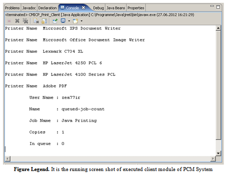 | Figure 9. PCM System; Client Module |
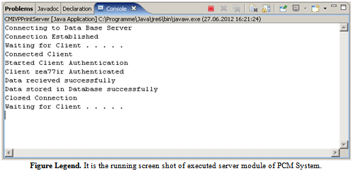 | Figure 10. PCM System; Server Module |
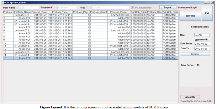 | Figure 11. PCM System; Admin Module |
5. Conclusions
- This manuscript has presented research being conducted in the fields of system, embedded and network programming. To give technical reader a complete idea about software application, presented major implemented UML designs. To familiarize user with software application, the graphical user interfaces of proposed software application has briefly described. In the end of the manuscript, successfully validating PCM System in a ten stepped processes, presented a case study as well.In future, enhancing this research and development work, an online user friendly web interface can also be developed which can provide access to the database using World Wide Web[27][28]. In addition to take advantage in extracting information efficiently, a natural language based search engine can also be developed or used (some existing)[29],[30],[31].
ACKNOWLEDGEMENTS
- Author is thankful to the University of Wuerzburg Germany and Vienna University of Technology Austria for letting initiate this research project, designing UML diagrams, developing software application and drafting this manuscript. Author pays special gratitude to Prof. Dr. Thomas Dandekar (Chair: Department of Bioinformatics, Biocenter, University of Wuerzburg Germany) for his generous support during the preparation this manuscript.Author is also thankful to the blind reviewers for peer reviewing and publishers for publishing this manuscript.
References
| [1] | Tischer. M, Jennrich. B, PC Intern: The Encyclopedia of System Programming (Developers Series), 6th edition, Abacus Software, 1996. |
| [2] | Potts. J, Printing Programming in Windows: Driving Special Printers with 3.5 Disk, Publishers Group West, 2000. |
| [3] | Stevens. WR, UNIX Network Programming: Networking APIs: Sockets and XTI, Prentice Hall PTR, 1998. |
| [4] | Hall. VB, Beej's Guide to Network Programming, Jorgensen Publishing, 2011. |
| [5] | Hyde. R, The Art of Assembly Language, No Starch Press, 2003. |
| [6] | Barr. M, Programming Embedded Systems in C and C ++, O'Reilly Media, 1999. |
| [7] | Ritchie. S, Systems Programming in Java, IEEE Micro archive, vol .17, no. 3, pp. 30-35, 1997 |
| [8] | Birrell. A,An Introduction to Programming with C# Threads, Microsoft Research Technical Report, no. 41, 2005. |
| [9] | Latronico. E, Koopman. P, Representing Embedded System Sequence Diagrams as a Formal Language, in Proceedings of 2001 4th International Conference on The Unified Modeling Language, Modeling Languages, Concepts, and Tools, pp. 302-316, 2001. |
| [10] | Ambler. SW, The Elements of UML 2.0 Style, Cambridge University Press, 2005. |
| [11] | Berardi. D, Calvanese. D, Giacomo. GE, Reasoning on UML class diagrams, Artif. Intell., vol. 168, no. 1, pp. 70-118, 2005. |
| [12] | Grant. ES, Chennamaneni. R, Reza. H, Towards analyzing UML class diagram models to object-relational database systems transformations. in Proceeding of 2006 24th IASTED international conference on Database and applications, pp. 129-134, 2006. |
| [13] | Medvidovic. N, Rosenblum. DS, Redmiles. DF, Robbins. JE, Modeling software architectures in the Unified Modeling Language, ACM Trans. Softw. Eng. Methodol., vol. 11, no. 1, pp. 2-57, 2002 |
| [14] | Jacobson. I, Christerson. M., Jonsson. P, Övergaard. G, Object-Oriented Software Engineering: A Use Case Driven Approach, Reading, MA: Addison-Wesley, 1992. |
| [15] | Bruza. PD, van der Weide. T, The Semantics of Data Flow Diagrams, in Proceedings of 1993 the International Conference on Management of Data, pp. 66-78, 1993. |
| [16] | Marilyn. B, “A guide for programmers”. Prentice-Hall. 1978. |
| [17] | Hyde. Paul, "Java Thread Programming", Sams, 1999. |
| [18] | Ahmed. Z, Towards Performance Measurement and Metrics based Analysis of PLA Applications, International Journal of Software Engineering & Applications, vol. 1, no. 3, pp. 66-80, 2010. |
| [19] | PaperCut, http://www.papercut.com/ |
| [20] | CZ Print Job Tracker, http://www.czsolution.com/ |
| [21] | A.N.D.Pcounter, http://www.andtechnologies.com/index.php?q=printing-solutions |
| [22] | Cyclope Print Management Software,http://www.cyclope-series.com/printer-monitor/print-management-software.html |
| [23] | HP Web Jetadmin software,http://www.hp.com/united-states/web-jetadmin/index_f.html |
| [24] | Ahmed. Z, Ali. M, Saman M, Implementing Computerized and Digitally Mobile Home Automation System towards Electric Appliance Control and Security System, International Journal of Emerging Sciences, Vol. 1, No. 3, pp. 487-503, 2011 |
| [25] | Ahmed. Z, Sudhir. G, Hans. K, Design Artifact's, Design Principles, Problems, Goals and Importance, in Proceedings 4th International Statistical Conference, pp. 57-68, 2008. |
| [26] | Ahmed. Z, Designing Flexible GUI to Increase the Acceptance Rate of Product Data Management Systems in Industry, International Journal of Computer Science & Emerging Technologies, Vol. 2, No.1, pp. 100-109, 2011. |
| [27] | Ahmed. Z, Dandekar. T, Saman. M, Semantic web; Ontology Specific Languages for Web Application Development, International Journal of Web Applications, Vol. 4, No.1, pp. 33-41, 2012. |
| [28] | Ahmed. Z, Saman. M, Middleware Technologies; Chain Web Grid Services, International Journal of Web Applications, Vol. 3, No. 4, pp. 197-205, 2011. |
| [29] | Ahmed. Z, Dandekar. T, Saman. M, Role of Ontology in NLP Grammar Construction for Semantic based Search Implementation in Product Data Management Systems, International Journals of Management, IT & Engineering, Vol. 2, No. 2, pp. 1-40, 2012. |
| [30] | Ahmed. Z, Saman. M, NLP Syntax Structure using ANTLR in I-SOAS, International Journal of Information Technology and Engineering, Vol. 2. No. 2, pp., 2011. |
| [31] | Ahmed. Z, Proposing LT based Search in PDM Systems for Better Information Retrieval, International Journal of Computer Science & Emerging Technologies, Vol.1, No. 4, pp. 86-100, 2010. |
| [32] | ObjectPrint, http://www.fitosoft.com/ |
| [33] | PaperCut, http://www.papercut.com/ |
| [34] | Ahmed.Z, I-HMI and LT-SOS in PDM Systems; Implementing AI Concepts for The Advancement of Multiple Role Based User Oriented Product Data Management Systems,VDM Verlag Dr. Müller Publishers, 2011. |
| [35] | Ahmed. Z, Ali. M, Smart House; Towards Artificially Intelligent Home Automation System,VDM Verlag Dr. Muller Publishers, 2011. |
| [36] | Ahmed. Z, Ele-Comp-Hus: Digitally Mobile and Computerized House, LAP Lambert Academic Publishers, 2010. |