Hicham Megnafi , Noureddine Boukli Hacene
Telecommuniation Laboratory of Tlemcen, Univ-Abou Bakr Belkaid, B.P N° 119, Tlemcen, Algeria,
Correspondence to: Hicham Megnafi , Telecommuniation Laboratory of Tlemcen, Univ-Abou Bakr Belkaid, B.P N° 119, Tlemcen, Algeria,.
| Email: |  |
Copyright © 2012 Scientific & Academic Publishing. All Rights Reserved.
Abstract
There have been increasing demands for advanced RF/Microwave filters other than conventional Chebyshev filters in order to meet stringent requirements from RF/Microwave systems, particularly from wireless communications systems. In this paper, we will analysis the cascaded quadruplet (CQ) filters by an iterative method based on the wave concept, combined with the module of the approach multi-scale. The novelty of this method consists in substituting selected coarse meshes by their equivalent surface impedances. This approach offers high spatial resolution with low computing resources. The results are presented and analyzed to demonstrate its efficiency.
Keywords:
Iterative Method, Microwave, Concept Of Waves,S Parameter,Microstrip Cascaded Quadruplet Filters, Multi-Scale
Cite this paper:
Hicham Megnafi , Noureddine Boukli Hacene , "Analysis Of MicroStrip cascaded Quadripolet Filters by a Multi-Scale Wave Concept iterative procedure (M.WCIP)", Software Engineering, Vol. 2 No. 4, 2012, pp. 101-105. doi: 10.5923/j.se.20120204.02.
1. Introduction
For many years, microwave circuits are getting more complex but with a smaller size. These two points imply, in most cases, the coexistence in the same circuit of different scales of sizes. Classical numerical approaches have two major drawbacks to solve such problems. They are the usual design engineer nightmares: the need of large memory resources and especially a long computation time, due to the finest grid[1].The solution of problem of the relation between circuit complexity and the resolution of the spatial domain can be obtained by using multi-grid levels or multi-resolution approach[2].There is not much literature covering numerical methods that allow several stages of space resolution. However, some multigrid approaches have been studied using the “multigrid TLM (Transmission Line Modelling) method”[3-4] with different mesh sizes to describe space domain by a fine grid. The TLM method has been used to simulate the phenomenon of wave propagation in the temporal domain. In addition, G.Deng[5] presents the sketch algorithm decomposing an image into three levels using wavelet transform. Most of these approaches deal with the electromagnetic problems thanks to different types of mesh sizes in the same grid.The multi-scale formulation is not usually exploited but here, it is used by the iterative method. This approach is studied for an accurate global analysis of planar circuits usually characterized by jagged structures. The iterative method formulation[4-6] is based on a recurrent relation between in-coming and out-going waves with respect of the boundary conditions in the spatial domain. The result is progressively approached by iterations and considered correct when converging[7].In this study and to overcome these difficulties the presented formulation tends towards a multi-scale discretisation. We present a new iterative method M.WCIP based on a combination between the approach multi-scale and by iterative method classic. The results were compared with another work cited in[8] and by iterative method classic WCIP. Finally, the prospects will conclude this study.
2. Iterative Method
In this paragraph, we introduce the definitions of all important values in order to present the WCIP principle.
2.1. Concept of waves
The WCIP is developed in terms of waves, which are defined as a combination of the electric field  and the transverse current density
  in terms of incident and reflected waves .These incident
  and reflected
  at the boundaries interfaces on one side Ω. These waves are described by the following formulation[10]:
 | (1) |
 | (2) |
With: | (3) |
 | (4) |
Where: the intrinsic impedance of the medium i.
 the tangential magnetic field.
 the unit vector normal to Ω and directed into region i ( i = 1 or 2).
 ,
, and
and  are respectively the permittivity and permeability of the vacuum, the relative permittivity of the medium i, and the permeability of the vacuum
2.2. Procedure of the WCIP
According to the criterion defining the wave concept, we can define the electric field and the current density values in each point of the surface Ω by the determination of the incident waves and the reflective waves values. So, the iterative process is based on the creation of a recurrence relation between the incident waves and the reflective waves, and the repetition of this relation until obtaining the problem solution.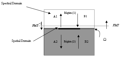 | Figure 1. Example of an image with acceptable resolution |
The iterative method can be summarized by the following equations system[11]: | (5) |
 | (6) |
Where: The diffraction operator in the interface.
 The reflection operator on the covers.
 The wave creates by the source in the space field.
 The total electric field produces by the excitation source.The diffraction operator is defined in the space field, on the interface Ω containing the circuit. It translates the conditions on the boundaries, the tangential fields continuity relations and the current density on each interface sub field. It is defined by the relation (7)[6].
 | (7) |
With[1]: | (8) |
 | (9) |
 | (10) |
 | (11) |
Where:
 = 1 on the metal and 0 elsewhere.
 = 1 on the dielectric and 0 elsewhere.
 = 1 on the source and 0 elsewhere.
 ,
, ,
, ,
, depend on the type of used source[11].
 ,
,  the intrinsic impedance of the medium 1 or 2.The representative of each medium reflection operator is directly deduced from admittance expression as (12) :
  | (12) |
Where:i indicates medium 1 or 2. the intrinsic impedance of the medium i.α indicates mode type TE or TM.
 The admittance operator brought in the dielectric interface plan i for the mode α.The admittance calculation depends on the medium height h, on the considered medium, on the used cover type and the mode (TE or TM)[12].
 | Table 1. Admittance of cover |
| | Type of cover |

| | Short-circuit |

| | Open space |

|
|
|
Where[11] : | (13) |
 | (14) |
In equations (13) and (14),  ,
, and
and are respectively the permittivity of the vacuum, the relative permittivity of the medium i, and the permeability of the vacuum.
 is the medium i constant propagation which is defined as follows[11-13]
 | (15) |
With a and b are dimensions of the guide of wave and  is the wave number in the free space
2.3. Fast Modal Transform
The Fourier Transform fundamental principle in Fast Modal Transform (FMT) is described by the following relations[12]: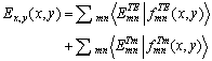 | (16) |
 the components of the electric field vector defined in spatial domain.
 and
and  the components of the electric field vector defined in modal domain.
 are the expansion functions, which are suitable for representing the box circuit, and can be obtained by considering the modes of a waveguide bounded by four electric walls.
3. Multi-Scale
To apply the iterative method, a first spatial meshing is required. When the dimensions of the material do not correspond to an exact number of pixels, called macro-pixels, a smaller local meshing of this particular pixel, called a sub-pixel, is made to adjust the circuit design according to its real geometrical dimensions (Figure 2). In these particular macro-pixels, sub-pixels interact. A macro-pixel enclosed in the chosen limits (electrical, magnetic or periodical walls) constitutes a guide G. The equivalent surface impedance that characterizes this part of the circuit is used to represent this macro-pixel[2]. | Figure 2. Sub-pixel location in an unspecified circuit |
The fundamental mode is sufficient to describe the interaction of macro-pixels, the effects of higher harmonics is negligible[6]. To evaluate the surface impedance, we suppose that the macro-pixel constitutes an iris in waveguides with periodic walls. The new boundary conditions involve a novel definition of the FMT. In the traditional waveguide, the lateral walls are electric or magnetic and the FMT has an expression in sines and cosines. With periodic condition, we use FMT with exponential development. The studied structure is excited by a spectral waves A0 and the surface impedance is deduced from the ratio of the electric and magnetic fields[9].
4. Multi-scale WCIP Algorithm
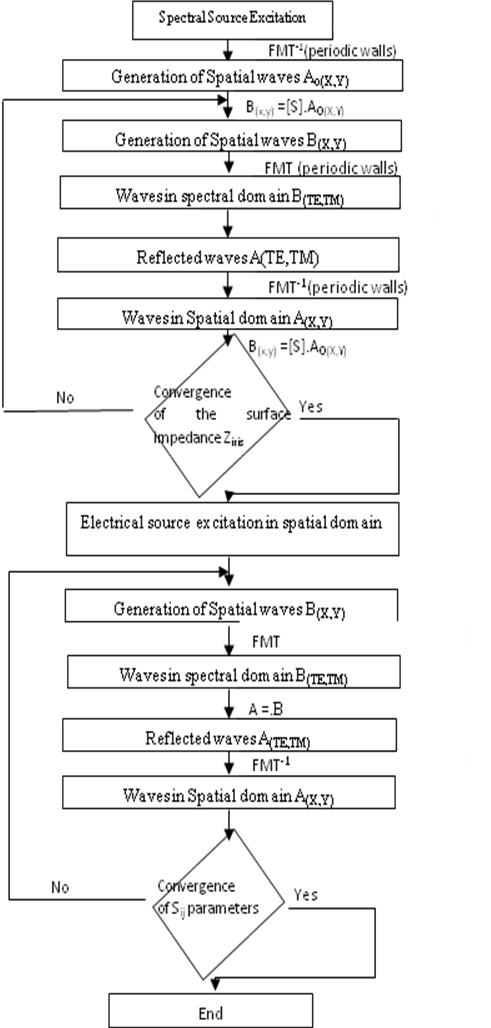 | Figure 3. Multi-scale.WCIP Algorithm[10] |
Where, is the diffraction operator in the interface,  the reflection operator on the covers, the fast modal transform FMT assures wave transformation from the spatial to the spectral domain, and its inverse (FMT-1), transformation back.
5. Results
The new formulation of the iterative method is applied to layouts of the microstrip cascaded quadruplet (CQ) filters. Our obtained results will be compared with another work cited in[14].The application example that we simulate is a Layout of the cascaded quadruplet (CQ) filter designed to have a higher selectivity of the pass-band. It is showed in figure 4.The layout of the designed micro-strip cascaded quadruplet (CQ) filters with the dimensions on a substrate having a relative dielectric constant of 10.8 and a thickness of 1.27 mm. 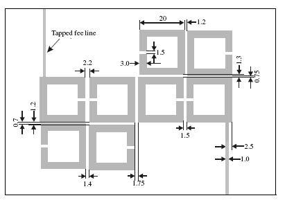 | Figure 4. Layout of the designed microstrip cascaded quadruplet (CQ) filters |
Figure 5 shows the frequency responses of the microstrip cascaded quadruplet (CQ) filters obtained by iterative method classic (WCIP), Multi-Scale iterative method M.WCIP and by[14].  | Figure 5. simulated frequency responses s21 and s11 of the the microstrip cascaded quadruplet (CQ) filter.obtained by WCIP, M.WCIP and by[11] |
This result was validated with iterative method classic WCIP but by height mesh of this layout, and according to the results presented in[14].
6. Conclusions
In this work, we present the principle point of iterative method. Then we are devoted to the development of a multi-scale iterative method based on the wave concept has been described. The obtained results are of similar accuracy compared to those of a uniform fine mesh and with results obtained by other researcher. Furthermore, this multi-scale method can be used to improve resolution, while reducing calculation time and computer storage requirements.
References
| [1] | F. Surre, L. Cohen, and H. Baudrand, " New approach for multi-scale circuit analysis", 31th European Microwave Conference (EUMC), Lenders, Royaume-Uni, September 2001. |
| [2] | L. Cohen, R.S. N’Gongo, R. Garcia and H. Baudrand, "Equivalent impedance boundary conditions for refined meshes applied to planar circuits", IEE Proc.-Microw. Antennas Propag., Vol. 150, No. 4, August 2003 |
| [3] | Wlodarczyk, J, "New multigrid interface for the TLM method", Electron. Lett., 1996, 32, (12), pp. 1111–1112 |
| [4] | Deng, G. , "Grey scale image representation using binary sketch image", Electron. Lett., 1996, 32, (10), pp. 881–882 |
| [5] | N’gongo, R.S., and Baudrand, H, "Application of wave concept iterative procedure in planar circuit", Recent Res. Devel. Microw. Theory Tech., 1999, 1, pp. 187–197 |
| [6] | Sboui N., A.Gharsallah, H. Baudrand, et A. Gharbi, " Analysis of double-loop meander line by using an iterative process", Microwave and optical technology letters/vol. 26, no. 6, September 20 2000. |
| [7] | Fontgalland G., P.I.L.Ferreira, T.-P.Vuong, N.Raveu et H.Baudrand, " Analysis of asymmetric PBG ground planes for wireless communications ", IEEE Explore 0-7803-9342-2/05,November 2008 |
| [8] | H. Baudrand, N. Raveu and N. Sboui , " Applications of Mulitscale Waves Concept Iterative Procedure ", IEEE transactions on microwave theory and techniques, Vol.53, n°1, pp 200-213, January 2005. |
| [9] | H. Zairi, A. Gharsallah, A. Gharbi and H. Baudrand , " Analysis of planar circuits using a multigrid iterative method", IEE Proc.-Microw. Antennas Propag., Vol. 153, No. 3, June 2006 |
| [10] | N.Sboui , A.Gharsallah, H. Baudrand, et A. Gharbi, “Analysis of double-loop meander line by using an iterative process”, Microwave and optical technology letters/vol. 26, no. 6, September 20 2000. 8 |
| [11] | M.Titaouine, A. Gomes Neto H. Baudrand, F. Djahli, “Analysis of Shorted Ring Slots FrequencySelective Surfaces Using WCIP Method”, Journal of Microwaves, Optoelectronics and Electromagnetic Applications, Vol. 7, No. 2, December 2008. 12 |
| [12] | M.Glaoui, E.A Hajlaoui, H.Zairi, H.Trabelsi,et H.Baudrand, “Modelling of non linear Elements using an extended Iterative method “, MicroWave and optical technology letters/Vol. 49, No. 1, January 2007. 13 |
| [13] | G..Fontgalland, P.I.L. Ferreira, T.-P. Vuong, N. Raveu, R. Garcia and H. Baudrand, “Multlayers EBG structures design by fast wave concept iterative procedure”, Proceedings of ICT’04, LNCS, poster, Fortaleza, Br, July, 2003. 10 |
| [14] | Jia-Sheng Hong, M. J. Lancaster, " Microstrip Filters for RF/Microwave Applications", John Wiley & Sons, Inc., 2001, pp 328-330 |
 Abstract
 Reference
 Full-Text PDF
 Full-Text HTML