-
Paper Information
- Paper Submission
-
Journal Information
- About This Journal
- Editorial Board
- Current Issue
- Archive
- Author Guidelines
- Contact Us
Science and Technology
p-ISSN: 2163-2669 e-ISSN: 2163-2677
2021; 11(1): 1-6
doi:10.5923/j.scit.20211101.01
Received: May 17, 2021; Accepted: May 30, 2021; Published: Jun. 15, 2021

Numerical Simulation of Shock Wave in Water by the Laser Induced Force
 Abstract
 Reference
 Full-Text PDF
 Full-text HTML
R. Hemel
Department of Mathematics, Jahangirnagar University, Savar, Dhaka, Bangladesh
Correspondence to: R. Hemel, Department of Mathematics, Jahangirnagar University, Savar, Dhaka, Bangladesh.
| Email: |  |
Copyright © 2021 The Author(s). Published by Scientific & Academic Publishing.
This work is licensed under the Creative Commons Attribution International License (CC BY).
http://creativecommons.org/licenses/by/4.0/

The present research investigates the shock wave strength in water generated by laser irradiation through a shock driver. A flat glass coated with thin metal plate is considered as shock driver, which is kept at the top surface of water for shock simulation. Here, five different thin metals have been used as coat of shock driver such as titanium (Ti), nickel (Ni), gold (Au), aluminum (Al) and silver (Ag). By the laser irradiation, a thermo-elastic expansion arise into the metallic plate of shock driver very promptly and, consequently a longitudinal wave propagates through the metal with very high amplitude in very short time. The longitudinal wave carries the momentum and energy from laser and as a result, a shock wave propagates into water. The finite difference method is applied for shock simulation in water using the conservative form of Euler equations of motion. In the simulation, the laser induced force is used as boundary condition, which arise from the shock driver, and calculated from the thermo-elastic wave equations. Finally, among the all metals, the numerical simulation shows that the strongest shock wave is originated by titanium metal.
Keywords: Shock wave, Longitudinal wave, Thermo-elastic wave, Shock driver, Momentum and energy
Cite this paper: R. Hemel, Numerical Simulation of Shock Wave in Water by the Laser Induced Force, Science and Technology, Vol. 11 No. 1, 2021, pp. 1-6. doi: 10.5923/j.scit.20211101.01.
Article Outline
1. Introduction
- The applications of shock wave play a vital role in several different fields such as bio-engineering, material sciences, geosciences, physics, molecular biology, medical sciences [1], [2], [3]. However their properties and definitions may vary from one field to another depending on shock wave applications. The present research is focused on numerical analysis for finding the shock wave strength induced by laser irradiation. The study of shock wave strength is a considerable research for its successful outcomes in bio-engineering and medical sciences. Its application is very common in many treatments as well such as drug delivery, neurosurgery, to break the gallbladder stones without surgery etc. [4], [5].The principle of laser induced shock wave generation in solid or fluid media has been studied in theoretically and numerically for understanding dependency of shock velocity and pressure. Several kinds of techniques for shock generation are used to control the shock velocity and pressure for different applications as well. The interaction of laser light with metal is very interesting as a variety of physical process take place depending on laser specifications such as laser frequency, pulse duration, power, beam spot size etc. In this work, very low laser intensity is considered so that the material surface does not melt but expands promptly due to the rapid thermal process, which is recognized as thermo-elastic process. In this mechanism, when laser light irradiated the material surface, few wave modes are produced in the solid. Primarily, a longitudinal wave propagates through the metal, and this wave has a sharp peak intensity and velocity compared with the other waves. It transports the momentum and energy from laser to produce the shock wave. Several investigations have been carried out about the thermo-elastic wave generation induced by pulsed laser, where analytical methods are used to obtained the solutions [6], [7]. In this research, numerical analysis of shock wave in water by laser induced force through a shock driver has been studied. Here a flat glass coated with thin metal plate is assumed as shock driver, which is kept at the upper surface of water. In numerical analysis, five different metals are considered as coat of shock driver such as titanium (Ti), nickel (Ni), gold (Au), aluminum (Al) and silver (Ag). Therefore, efficient shock driver may be select for a specific shock wave for a particular bio-engineering application. One dimensional conservative form of Euler equations of motion for compressible fluid is solved for shock simulation. In this study, laser induced force is used as boundary condition, which arise from the thermo-elastic expansion of shock driver and calculated from the governing thermo-elastic wave equations. The numerical method, MacCormack’s scheme is applied for shock wave simulation in water.
2. Methodology
- The laser induced sudden released energy on any material such as liquid, solid or gas may produce some effects such as ablation of material, formation of plasma or excitation and as a result, a shock wave can be generated. In this study, it has been considered that the laser energy released on a solid material, known as shock driver, by beam guided lens and which produced a thermo-elastic expansion of the shock driver very promptly and consequently, a shock wave is generated. The shock driver is equipped by a flat glass coated with thin metallic plate, as shown in figure 1. The main purpose of the use of flat glass is improving the absorption rate of the laser energy by the metallic plate. Our objective is to produce thermo-elastic expansion inside the metal plate. Therefore, it needs to take some special care during the laser irradiation, as at high laser irradiation intensity, a tiny layer of metal surface may be melts or plasma may generates. But, at relatively weak laser irradiation intensity, the metal surface does not melt. However, the metal surface expands very rapidly due to the laser induced a rapid thermal process, which is known as thermo-elastic effect [8]. During this thermal process, several types of wave propagates through the metal surface such as longitudinal wave, shear waves, Rayleigh waves, head waves etc. The shear wave propagates through the solid metal with nearly half of the velocity of the longitudinal wave [9]. On the other hand, a longitudinal wave propagates through the metal with its peak amplitude and fastest speed compared with the other waves such as shear waves, Rayleigh waves, head waves etc. [10]. Therefore, according to the aim of this research, relatively low irradiation laser intensity is considered for introducing thermo-elastic effect on the metallic plate. Our goal is to produce a micro shock wave in water and for that it is considered, the shock driver is immersed into a water tank. Hence, in this process, the laser induced thermo-elastic expansion of shock driver generates the longitudinal wave, which carries the momentum from laser light and produced a micro shock wave in water. To generate shock wave in water by applying laser induced thermo-elastic expansion into the shock driver, the following experimental conditions are assumed in the present research.
2.1. Experimental Considerations
- A Q-switched Nd: YAG laser of 532 nm wavelength is considered with 5 ns pulse duration. The laser light is delivered from the back side of the coated surface of the flat glass or shock driver. The metal coating thickness is considered 100 nm, as [11] author shows that the 100 nm of metal coating of shock driver can produce effective shock wave. Shock driver is immersed into the water tank for shock generation into water shown as in Figure 1. The radius of the irradiation region of shock driver is fixed 1.5 mm which easily determined by Gaussian beam waist [12]. In this process, the laser induced thermo-elastic expansion of shock driver generates the longitudinal wave, which carries the momentum from laser light and produced a micro shock wave in water. The present research focus on the influence of different metals of shock driver on the propagation of shock wave in water. Here five different types of metal are considered as a coat of shock driver such as titanium (Ti), nickel (Ni), gold (Au), aluminum (Al) and silver (Ag). All these experimental conditions are considered in the numerical simulation.
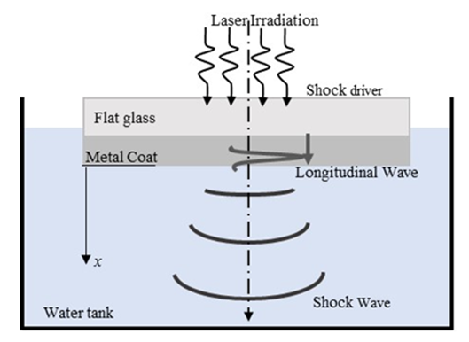 | Figure 1. Shock propagation in water due to laser irradiation through shock driver |
3. Mathematical Modeling
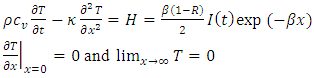
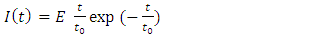
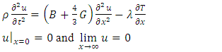
- An isotropic and homogeneous metal is considered as coating of flat glass. The x coordinate is chosen to originate from the metal surface to another end and the metal thickness is considered 100 nm only for effective shock generation [11]. The one dimensional governing equation for laser induced thermo-elastic wave in a metal are described by (1), (2) and (3) with initial and boundary conditions [11], [13], [14] and its general solution can be found by Laplace and inverse Laplace transformation techniques.
 | (1) |
 | (2) |
 | (3) |

 and H respectively. Heat sources are usually viewed as the Gaussian profile and is described by the Beer-Lambert law. I (t) is the laser intensity is given in equation (2) and R,
  is the reflectance and the absorption coefficient of the metal respectively. The boundary condition represents the system follows adiabatic approximation and temperature is zero at infinity. The equation (3) represents the displacement equation with boundary condition, where u is the displacement, B and G are the bulk and shear modulus of elasticity and
 is the volumetric thermal expansion coefficient. The Laplace transformation of the equation (1) and (3) are as follows,
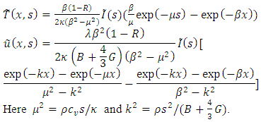
4. Numerical Methods
- The one dimensional Euler equations is used to solve the shock wave in water, which can be written in conservative form as follows [15], [16], [17],
 | (4) |
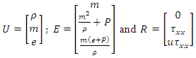 Here a set of continuum, momentum, and energy equations for compressible fluid has been used. In the above equation,
  is the density of water, P is the pressure,
  is the momentum, u is the velocity component in x – direction,
  is the specific internal energy of water,
  the specific heat at constant volume, T the temperature, and
  where
where  is the viscosity. In order to take compressibility of water into consideration, the modified Tait equation of state has been applied in the current calculation. It is given by as follows [18], [19],
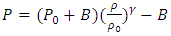 | (5) |
 = 7.15. P0 and
  are atmospheric pressure and reference density, respectively.This set of equations is used to solve the underwater shock wave problem by numerically. In this study, finite difference scheme, namely MacCormack’s scheme has been applied to the compressible water dynamics. This method is well known classical scheme and has two steps iteration such as predictor and corrector steps [17]. The forward difference is applied at predictor step and backward difference at corrector step for space derivative and the scheme has second order accuracy.
 4.1. Boundary Condition
- As water top surface is contacted with the metal and therefore, boundary condition comes from metal. At first, metal gains the momentum after laser irradiation, and this momentum has been carried by the longitudinal wave with drastic value change through the metal. Thus the longitudinal wave causes the pressure jump in water and it propagates as a shock wave. According to [11], authors established that the acceleration wave act as a front of longitudinal wave propagating through the thin metal of the shock driver and deliveries the laser induced force to the water for shock generation. Therefore, boundary condition is the laser induced force is,
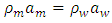 | (6) |
 is the density and a is the acceleration and subscripts m and w stands for metal and water. This relation represents the force balance per unit volume at the interface.
5. Result and Discussion
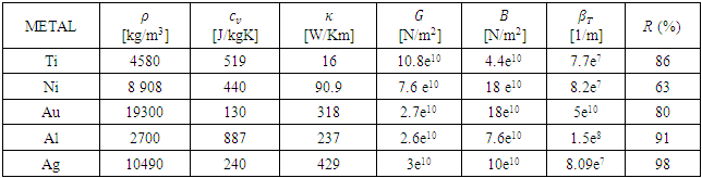
- First of all, calculations are carried out to investigate the longitudinal wave induced by laser irradiation for five different metals based on the solution of one dimensional thermo-elastic wave equations (1-3). Titanium (Ti), nickel (Ni), gold (Au), aluminum (Al) and silver (Ag) are considered for coating of flat glass. As the terminal surface of the metal transports the laser energy to water and resulting a shock wave propagates into the water. Then, we will observe the metallic response by the thermo-elastic effect at the terminal surface of the metal i.e. at x = 100 nm. The authors in [11], said that the acceleration wave act as a longitudinal wave propagating through the thin metal of the shock driver and supplies the laser induced force for shock generation in water. Hence the acceleration wave will be calculated from the thermo-elastic effect of shock driver. The computation have been performed by MATLAB and the above discussed all experimental conditions are considered in the program. The computation is performed for different five metals with the physical properties shown in Table-1, where the notations ρ, cv, κ, G, B, βT, R (%) denote density, specific heat at a constant volume, thermal conductivity, shear modulus, bulk modulus, absorption coefficient, Reflectance rate at 532nm.
|
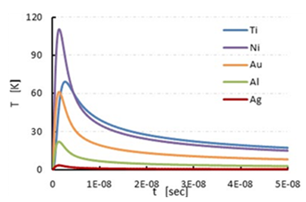 | Figure 2. Temperature response |
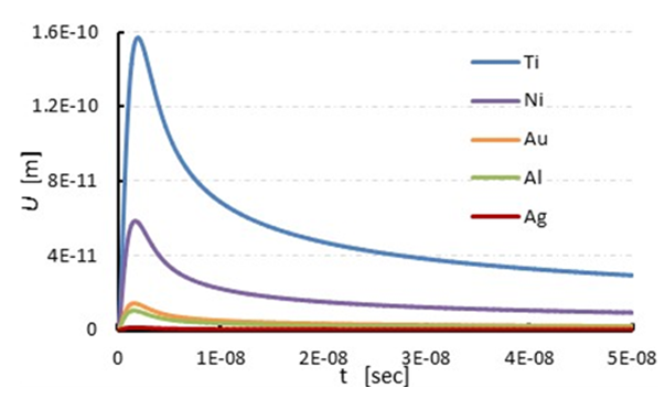 | Figure 3. Variation of displacement |
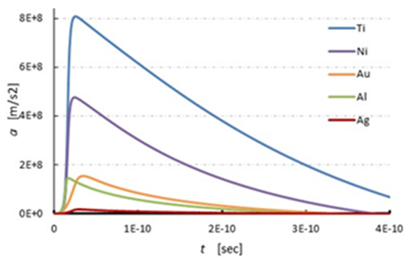 | Figure 4. Acceleration wave which is act as a longitudinal wave |
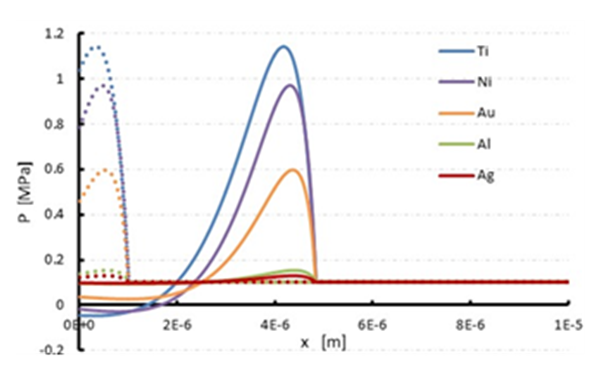 | Figure 5. Shock wave pressure in water at different time |
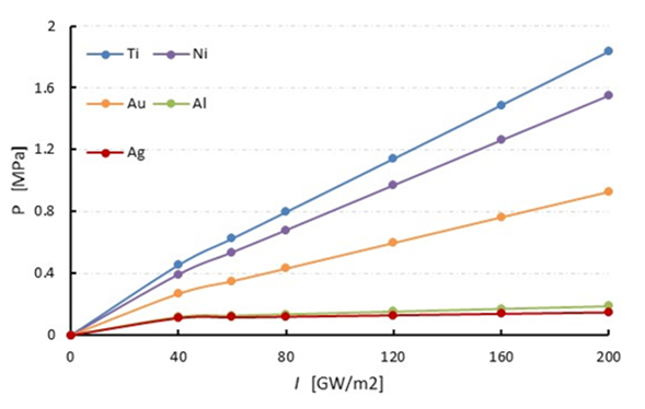 | Figure 6. Comparison of shock pressure in water for different laser intensity |
6. Conclusions
- In this research, numerical simulation of shock wave propagation in water has been studied. The shock wave is generated by laser irradiation through the shock driver, where five different metals is used as coat of shock driver such as titanium (Ti), nickel (Ni), gold (Au), aluminum (Al) and silver (Ag). The MacCormack’s scheme is applied to the Euler’s equation of motion for shock wave simulation in water. The laser induced force is used as boundary condition, which is calculated from thermo-elastic wave equation. This boundary effect comes from shock driver as water upper surface is contacted with shock driver. Among the all metals, strongest shock pressure arise from titanium metal, about 1.2 MPa and silver metal produced lowest strength shock wave. It also found that shock strength increase with the increase of laser irradiation intensity. Moreover, it also confirmed that the acceleration wave act as a front of longitudinal wave propagating through the thin metal of the shock driver and deliveries the laser induced force to the water for shock generation.
ACKNOWLEDGEMENT
- The the authors are very grateful to Prof. H. Hirahara, Mr. K. Takahashi for their help and contribution in carrying out research.