Science and Technology

p-ISSN: 2163-2669    e-ISSN: 2163-2677

2018;  8(2): 35-45

doi:10.5923/j.scit.20180802.02


Arc Motion in Low Voltage Circuit Breaker (LVCB) Experimental and Theoretical Approaches

J. Quéméneur, J. Lu, J-J. Gonzalez, P. Freton

Université de Toulouse, UPS, CNRS, INPT, LAPLACE (Laboratoire Plasma et Conversion d’Energie), France

Correspondence to: J-J. Gonzalez, Université de Toulouse, UPS, CNRS, INPT, LAPLACE (Laboratoire Plasma et Conversion d’Energie), France.

Email:

Copyright © 2018 The Author(s). Published by Scientific & Academic Publishing.

This work is licensed under the Creative Commons Attribution International License (CC BY).
http://creativecommons.org/licenses/by/4.0/

Abstract

This paper is related to the study of the arc motion in simple low voltage circuit breaker geometry. Experimental and theoretical approaches are investigated respectively by fast camera and by a magneto hydrodynamic model. Two theoretical methods have been developed to characterize the arc movement called MECM (Mean Electrical Conductivity Method) and GCRM (Global Current Resolution Method). The results obtained by the two models are in good agreement with the experimental observations. The MECM allows obtaining faster results but the stagnation phases are well represented with the GRCM and this last method is easier to implement in more complex geometry. The results show also the importance of the exhaust description on the arc behavior.

Keywords: Low voltage circuit breaker, Experiments, Plasma modelling, Arc motion

Cite this paper: J. Quéméneur, J. Lu, J-J. Gonzalez, P. Freton, Arc Motion in Low Voltage Circuit Breaker (LVCB) Experimental and Theoretical Approaches, Science and Technology, Vol. 8 No. 2, 2018, pp. 35-45. doi: 10.5923/j.scit.20180802.02.

1. Introduction

Low voltage circuit breaker (LVCB) is key element of electrical equipment in the power distribution systems. It is used to protect electrical machines from power defaults and to protect humans. In LVCB, when a fault current occurs, the contacts are separated and arc plasma appears between them. During the arc life, the protection is not effective as an arc exists first between one runner and a moving contact then between the two runners. This arc is submitted to electromagnetic and gas flow forces. The electromagnetic forces are due to the current circulation in the runner and in the arc plasma, creating respectively external and auto induced magnetic fields. Under the influence of these forces and due to the bending of the arc, generally the arc jump from the moving contact to the runner before the total opening of the moving contact [1]. Then the arc under the influence of magnetic forces and gas pressure [1, 2] is pushed into the plates to be split, cooled and extinguished by the effect of the current intensity limitation [2]. A general scheme of LVCB is presented Figure 1. During the arc life its motion depends on several effects: (1) LVCB uses the polymers vapors as polyoxy-methylene (POM) or polyamide 6 (PA6) coming from sidewalls. Vapors are ablated from sidewalls due mainly to plasma radiation. They change the plasma properties and increase the arc velocity [3]. We can quote papers from the literature studying the plasma properties of mixtures composed by air and PA6 [4-6]. These data banks are used by authors who have studied the plasma-wall interaction and the influence of the vapors on the arc behavior [7].
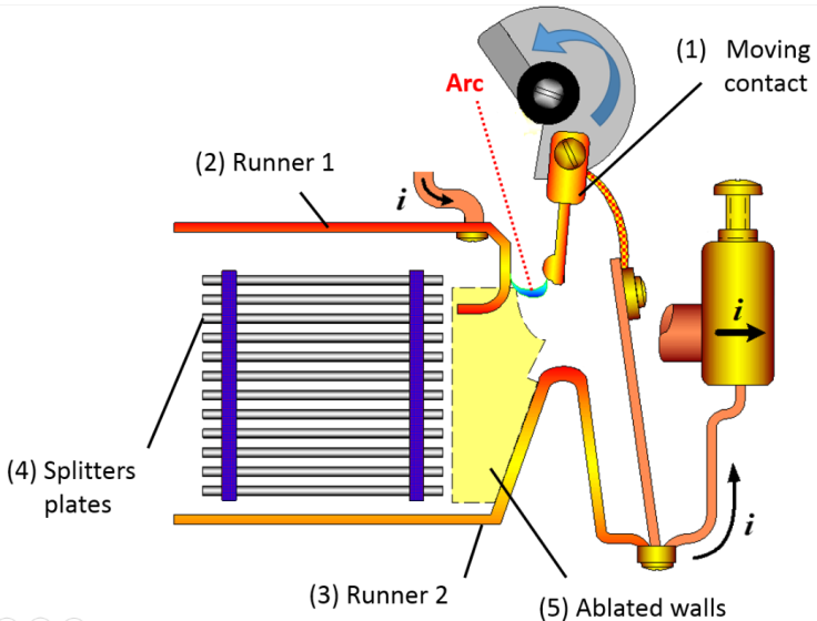
Figure 1. General scheme of LVCB
Others authors have directly assumed one amount of vapors to study the influence on the arc motion in the chamber [3]. (2) In the chamber the arc is driven to the splitters plates [1, 2], nevertheless during the displacement depending on the nature of the medium, on the local temperature and on the chamber geometry back restrikes can occur [1-2, 7-8]. Due to the complexity and to numerous physical mechanisms, the arc behavior is mainly studied in simplified geometries [9, 3] in order to focus on particular points like ferromagnetism [1, 10-13], eddy currents [14] or material ablation [9, 15-18]. Nevertheless some works tend to simulate arc behavior in real circuit breaker configuration [19-21]. The arc motion is an important point of the arc behavior understanding. It can be studied by the development of models allowing to access to numerous physical quantities or by experimental studies. Experimental studies allow obtaining current and voltage variations during the arc period. The arc position can also be determined by non-intrusive methods based on inverse methods [22-24] or by fast camera [8, 25, 17]. In these last studies the nature of one side wall should be changed from PA6 to plastic to allow the plasma observation.
The arc displacement in the chamber is not the only phase of the arc life even if this phase is essential. Indeed higher the arc velocity in the chamber, earlier the current limitation in the splitters plates occurs. Two others phases need to be considered: the opening with the commutation and the splitting. At the first instants of the opening the arc ignition must be represented by a non-equilibrium model. Due to the difficulty this phase in LVCB models is not represented and the first instants assume the existence of a conducting channel [26, 1] which can be represented under the assumption of plasma at local thermodynamic equilibrium (LTE). This conducting channel is assumed between the moving contact and one runner if the commutation phenomenon is studied even directly between the two runners. The main difficulty of theoretical arc representation resides on the current continuity between the runners and the arc. This continuity is satisfied by a non LTE sheath at the arc roots which must consider flux balances as proposed by Benilov [27-30]. Due to the phenomena complexity and high computational time in case of a three dimensional (3D) LVCB geometry others approaches are used. For example some authors at the cathode use a current density distribution to define the current source. The arc root position depends on criteria based on the mean electrical conductivity [3] or on the temperature [10, 31]. Depending on the criteria, restrikes [3] or arc roots slides on the runners [10, 31] can be represented. The arc interaction with material is also present in the last phase of the current interruption. Due to electromagnetic forces and gas flows the arc is driven to the cutting chamber constituted by several splitters plates. The arc segmentation by the splitters plate leads to an increase of voltage drop due to an elongation of the arc and to the multiplication of anodic and cathodic regions which add the voltage sheaths contributions [32, 2]. One more difficulty of the theoretical representation by a model is the current continuity between the runners and the plasma and through the splitters with the choice of the commutation criteria. One interesting approach presented by some authors [13, 33, 10] is based on experimental measurements [34, 35] and gives a correlation between the current density and the voltage. Depending on the arc bending the current density at the vicinity of the material (runners or splitters) gives a corresponding value of the resistivity and allows progressively the current to circulate. This method is used at the vicinity of the material through the definition of an effective electrical conductivity which depends of the sheath dimension and of the value of the current density [10, 13, 33, 36]. This method was successfully applied in LVCB geometry to represent the increase of the voltage due to the presence of the arc in the cutting chamber [13, 33, 10].
The difficulties on the experimental LVCB studies reside for the experimental part to the interruption time lower than 20ms, to the small dimensions and the complexity of the geometry, to the non-access of the arc due to opaque side walls (PA6), to the reproducibility due to change of the runners state. Nevertheless experimental measurements are necessaries for confrontation with theoretical results and their validation. For the model the difficulty is to represent all the phases of the interruption: arc ignition, elongation, commutation, displacement, eventually restrikes, arc bending, split of the arc in the cutting chamber and extinction. The global study must consider a moving contact in a 3D geometry [37], sometimes turbulence effects [1], vapors coming from the runners, the splitters plate and the side walls [18], eddy current [13], electromagnetic effects due to the current path and self-induced magnetic field [2], arc movement in the chamber, sheath description, commutation criteria on runners and splitters. Of course the mechanisms need to be separate for a better comparison between experimental and theoretical results.
In this paper we focus ours experimental and theoretical studies on the arc movement in the chamber. The arc ignition, the commutation to the runner and the cutting chamber with the current limitation are not considered. Indeed it is difficult to compare and to validate the arc movement in the chamber due to the fact that the arc commutation is much faster than the contact opening process. The arc typically jumps to the arc runner before a full opening of the moving contact [1]. One other important conclusion from the literature is that an increase speed of the moving contact will decrease the arc immobility time on the contact; this fact has been verified and is adopted in the LVCB’s produced by many companies [1].
Due to no physical representation of arc ignition, to differences which can appear in the comparison between experimental and theoretical works on arc commutation and on the contact opening representation a simplified geometry is used in this study by the experimental setup and by the model. The moving contact is replaced by a fuse and half wave current (10ms) is applied between the runners. In the model a conducting channel located at the same position than the fuse is used to describe the first instants.
In the first paper part the theoretical model developed to describe the arc plasma is presented with two methods for the description of the arc motion. In a second part the experimental results obtained by fast camera are discussed. The experimental and theoretical results are compared in order to well understand the arc motion and to define the more adapted of the two proposed models to describe the movement.

2. Numerical Model

2.1. The Geometry

Miniature Circuit Breakers (MCBs) are evolved in very complex geometries that lead for their study to meshing difficulty and make the interpretation complicated. Thus we choose to simplify the LVCB arc chamber to a 3D rectangular box with two parallel arc runners leading to a unidirectional arc displacement (Figure 2). Thus geometric parameters can be clearly defined: length, width, height, initial position of the arc, size of the gas exhausts. Moreover, such geometry can be easily meshed with hexahedra cells which provide higher mesh quality than tetrahedral and therefore a faster convergence of the calculation.
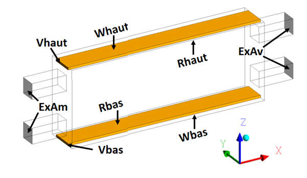
Figure 2. Simplified arc chamber geometry studied
To ensure coherence of the model, experiments are carried out in the same geometry with the same current. More details on the experimental setup can be found in [25].

2.2. Hypothesis

To reduce the calculation time and simulation complexity, several assumptions have to be made:
1) The medium is in Local Thermodynamic Equilibrium (LTE). This hypothesis has been validated [38] for the arc column but is arguable for peripheral region of the discharge and false in the plasma sheaths [30].
2) The special physic of the sheaths is ignored [26];
3) Turbulence is not taken into account;
4) Ferromagnetic effects or eddy currents are neglected; the induced current is assumed to be small in comparison with the applied current and its influence on the total current distribution is neglected [26, 39, 40]
5) The medium is assumed to be pure air as the walls ablation is not taken into account;
6) Arc ignition is not modelled. Calculation is started with a conductive channel which is either a fixed temperature if the gap is small or an energy source term applied for a short time in the case of a gap superior to several millimeters [26];
7) Gravity is neglected.

2.3. The Equations

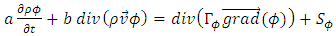
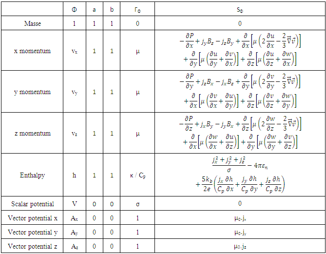
We use the Patankar formulation (Equation 1) to solve the magneto-hydrodynamics equations in transient state in a 3D coordinate system with a finite volume method (FVM). The diffusion coefficient ΓΦ and the source term SΦ depend on the physical quantity Φ considered as described in Table 1 where P is the pressure; Bx, By and Bz are the components of the magnetic field on the x,y,z directions; Jx, Jy and Jz are the components of the current density on the x,y,z directions; εn is the net emission coefficient, kb is the Boltzmann constant, e is the elementary charge and µ0 is the void magnetic permeability.
(1)
Table 1. Terms of the conservation equation for the physical quantities calculated
     
Radiative energy exchange is treated with the net emission coefficient. The transport properties have been previously calculated and tabulated for pure air [41]. Magnetic field is calculated using the potential vector formalism in the fluid domain. The Biot & Savart equation is calculated on the boundary conditions in order to have a good estimate of the potential vectors [42] and to take into account the external magnetic field due to the current circulation in the runners.
In addition to this thermal plasma model, specific developments must be carried on to describe arc roots movements on the runners.

2.4. Methods for Arc Motion

Whereas the electrical arc model described above is commonly accepted and used [43], there is no consensus on the way to describe arc-wall interaction and arc root movement on the electrodes. Nevertheless, this arc displacement is a critical point of the LVCB operation. For this purpose, one can describe an energy exchange at the plasma/material interface or adapt electrical conductivity in this region.
Early works on arc movement modelling have been performed in the Technical University of Braunschweig in 1998 [44]. Arc attachment uses the Richardson’s law which describes the thermo-ionic emission on a hot cathode, but the electrode material considered is copper which boiling point is under 3000K. Not taking into account emission by field effect could leads to errors on current density calculation up to 175% [45]. Another arc displacement method [33, 31] developed by the same group is more widely used [19, 18]. This is an empirical sheath model where the electrical conductivity in the cells adjacent to the electrode is not calculated with the gas properties but determined by the current density. Based on sheaths voltage drop measurements, a non-linear conductivity is fixed to obtain 10V on the layer surrounding the electrode. This has the two advantages of achieving a correct estimation of the total arc voltage and ensuring a sufficient electrical conductivity close to the electrode to allow a small current to flow. In the work of Piqueras et al. [46], arc attachment is self-determined with very few adjustment parameters. The voltage difference between anode and cathode is controlled so that the current gets the required value. Furthermore, electrical conductivity in the cell neighboring the electrode is imposed as the one of the metal to make sure the current can easily flow out of the electrode.
In the method developed by Rondot [47], an energy balance on the plasma/material interaction is tuned with adjustment parameters. Like in the work of Piqueras [46], there is a layer of 1 mm with high electrical conductivity all around the electrodes.
A more precise description of the physic of the anode [48] and cathode [30] would be a solution to simulate the arc movement but may be too complicated to implement and may cost a precious simulation time.
In this work, we used two different arc movement methods to compare and confront the results to the experiments.
2.4.1. Mean Electrical Conductivity Method (MECM)
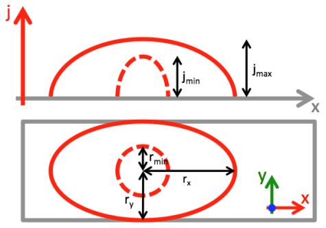
This first method is an improvement of Swierczynski's work [3]. The calculation domain close to the electrodes is separated in slices along the axis of displacement. The arc position is set where the mean electrical conductivity at the vicinity of the electrodes is maximal. The mean electrical conductivity is calculated in each slice and the position of the arc root is set at the coordinate with the highest mean value. The electrical conductivity of the cell is calculated depending on the local pressure and temperature.
As seen in experimental works [49, 50], there is more than one current path during arc commutation and restrikes. Thus, to model those processes, it is necessary to allow at least two arc roots on each runner. Therefore, the algorithm searches for slices where electrical conductivity is a local maximum. The two coordinates with the highest values being the positions of two arc roots. The total current is then shared between the two paths proportionally to the conductivity level (Figure 3). These positions are searched for each time step and classical steady state boundary conditions for anode and cathode may be used. For the anode position given by the algorithm, the scalar potential is imposed to zero volts and the electrode temperature is allowed to rise with a null Neumann condition. For the cathode, the current is imposed in the simulation with a parabolic current density distribution like in the work of Hsu [38] or Freton [51]. However due to a small width of the electrode and as the current can rise up to several kA the arc attachment can adopt an elliptic shape to allow more current to flow. Figure 4 shows the parabolic current density profile and the elliptic arc root shape that are determined by Equations 2-4.
Figure 3. Example of arc root determination on one electrode
Figure 4. Rendering of the current density profile on the electrode
The total current imposed on the surface is given by Equation 2 with Jmax= 1.2 108A/m2:
(2)
And the local current density is determined by:
(3)
(4)
The temperature is fixed at 3500K on the area where the current density profile is defined and 1000K outside.
The scalar potential in the electrodes is solved with separate scalars. The current density in the electrode vicinity (fluid side) is pasted on the faces inside the metal to solve the current conservation. Then the current conservation is also calculated in the runners to consider the magnetic field created by this current circulation. Three scalars are so necessaries to represent the current circulation in the whole domain.
2.4.2. Global Current Resolution Method (GCRM)
Another method considers heat and current exchanges between the electrodes and the plasma. The difficulty of this method is that the thermal and electrical conductivities between metal and plasma medium are very different. Therefore, improved algebraic multigrid methods [52] must be used to ensure current conservation. These results are obtained with a longer calculation time than the MECM.
The current is imposed in the simulation in the left end of the rail Vbas (Figure 2). The number of arc roots per electrode is undetermined, and varies from one to several. This method allows describing arc commutation and restrikes [53] and a self-determination of the arc movement without any adjustment parameters. Another advantage is its adaptability to complex geometries.

2.5. Boundary Conditions

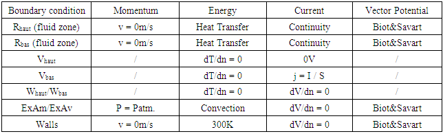
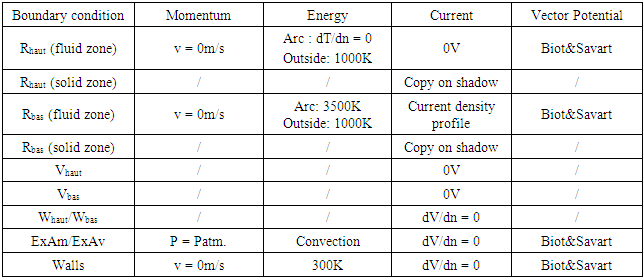
The geometry for the simulation is given in Figure 2 with the two rails (Rbas and Rhaut) and two gas exhausts on each side of the chamber (ExAm and ExAv). Current is fed through Vhaut and leaves the calculation domain through boundary Vbas thus the lower rail is the cathode. Whaut and Wbas are the back side of the rails and aren’t crossed by any flux. The other boundary conditions are labelled “Walls” in Tables 2-3 and refer to the plastic walls of the chamber.
Table 2. Boundary conditions for GCRM in the geometry shown in Figure 2
     
Table 3. Boundary conditions for MECM in the geometry shown in Figure 2
     
The gas velocity is not calculated of course in the solid domain and we assume a null velocity on the surfaces. For the energy equation a coupled method is assumed between the plasma and the runners taking into account the heat transfer. At the exhausts the temperature is fixed to a null flux depending on the sign of the convection. For the scalar potential, a homogeneous current density distribution is given at the entry Vbas, and V=0V at the exit Vhaut. This value corresponds to the reference potential. On the entire surfaces adjacent with the plasma the Biot & Savart formulation is used to define the boundary condition for the scalar potential. This Biot&Savart formulation allows taking into account the external magnetic field dues to the current circulation in the runners as the integral is calculated in the whole domain.
For the initial state of the arc, a conductive channel is created between the two runners by injecting energy in a cylinder diameter d=5mm during a short time. For this method the conditions are the same excepted for the energy and current conservation equations on the runners. With this method three scalars are used for the current conservation, one to solve the current conservation from the entry of the current intensity to the cathode arc root, the second from the anode arc root to the exit of the current and the third one in the plasma from one arc root to the other.
On a coupling edge, it exits two walls one on the plasma side and the shadow wall in the material. The scalar potential resolution is so calculated as in a classical configuration with a current density profile on the cathode runner and a zero value of the scalar potential on the anode side. For the two runners the current density profiles from the plasma walls is duplicated on the shadow walls and a zero reference value is assumed at the two extremities (Vhaut and Vbas). Two scalars are solved in the material to conserve the current. The temperature of the runners is assumed to be T=1000K. Then on the area of the arc attachment a zero flux condition is imposed on the anode side and T=3500 K on the cathode.

3. Experimental Study

3.1. Arc Chamber

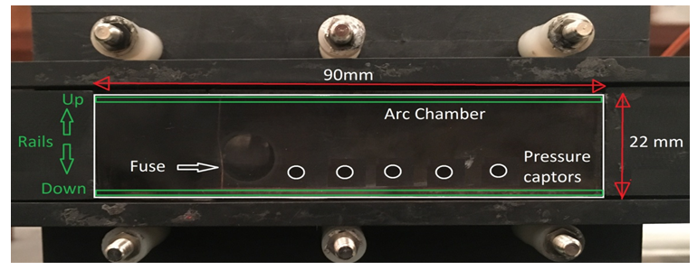
Due to the lack of space, natural MCB chambers are curved which makes analysis of the movement more complicated. To realize a parametric study we need to define simple arc chamber geometry. Thus, we use the same rectangular geometry for both the experiment (see Figure 5) and the 3-D model. The walls are in PMMA, the front side being a transparent Plexiglas to permit optical measurements. The arc chamber has two parallel steel arc runners and two exhausts (2x19.6mm2) on each lateral side. The electrical arc is ignited by a fuse wire.
Figure 5. Rectangular geometry for experimental and model studies

3.2. Pulse Current Source

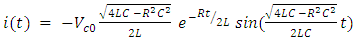
In our study, we focus on short-circuit fault in MCB that can reach prospective values up to 20kA. We therefore need an electrical source able to reproduce such current pulse. Four LC resonant circuits tuned to 50Hz are used in order to obtain a prospective peak current up to 13kA. The choice of the inductor-capacitor pair and the charging voltage allows adapting the current value according to equation 5.
(5)
Vc0 is the charging voltage of the capacitors and R, L and C respectively the equivalent resistance, inductance and capacitance. We use two TAS7 thyristors: the first one to feed the current to the device and a second one to interrupt the current and to discharge the capacitors. For the negative phases, a free-wheel diode is used.

3.3. Instrumentation

For high-speed imaging of the arc, we use a Photron Fastcam SA5, which can reach 1Mframe/sec. In ours measurements we use 100kframe/sec in order to keep a good resolution. The size of arc chamber being in the same order as the size of the CCD matrix we use a macro lens with a 105mm focal length. As the electrical arc is too bright, the aperture is kept minimal, which also improves the depth of field. Moreover, a neutral density filter of 128 is added and exposure time can be reduced to avoid overexposure of the picture and therefore loss of information. “Classical” electrical measurements are also performed with a differential voltage probe and Rogowski coils for the measurement of the current intensity.

3.4. Post-Treatment Software

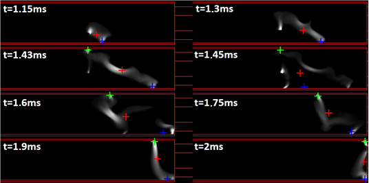
Breaking arcs present chaotic behaviors so it is better to perform statistical analysis on the experimental results before any interpretation. There are also some phenomena that are difficult to quantify such as restrikes, commutation and arc movement and an arbitrary determination by the user could lead to biases and randomness. For that matter, one tool was developed and used for the analysis.
The plasma in presence of an arc discharge is a bright and diffuse medium. To determine its position and movement from the pictures of the high-speed camera, a method must be specified. As suggested by McBride & al. [54], the arc can be tracked with a weighted average of the light intensity. In our study, the Centre Of Intensity (COI) method is used on all pixels of the frame or on specified areas like the vicinities of the runners in order to determine the global position of the arc or the positions of arc roots on the electrodes.
For a direct confrontation between experimental results and simulation, the same software is used to analyze the theoretical and experimental results. In this case the theoretical radiative losses obtained by the model need to be displayed in grayscale. The results of the model then are treated like experimental ones using the same algorithm for greater relevance. Typical pictures from the high-speed camera are displayed in Figure 6 and the adapted views of net emission coefficient are shown in Figure 7, we can observe similitude on the arc behavior between the theoretical and experimental results.
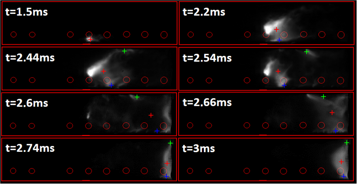
Figure 6. High-speed camera frames treated with the arc position software showing with green, blue and red dots the positions of the upper arc root, lower arc root and global position of the arc for a peak current of 1590 A
Figure 7. Views of the simulated net emission coefficient pictures treated with the arc position software showing with green, blue and red dots the positions of the upper arc root, lower arc root and global position of the arc for a peak current of 1608 A

4. Comparison of the Arc Motion Model

The methods to describe the arc moving on the electrodes must be validated. Therefore, in the same geometry, an arc is initiated between the two rails with a fuse wire in the experiment and by a conductive channel at the same position in the simulation. The displacement is characterized in Figures 8-9, I=1560A and the gas exhausts of the chamber are close or open.
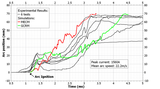
Figure 8. Experimental and simulated arc movements for fully open gas exhausts at medium current Peak current value 1560A
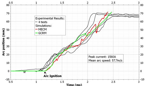
Figure 9. Experimental and simulated arc movements at medium current with closed upstream exhausts Peak current value 1560A
In the Figure 7 we give the arc position versus time. The position 70mm corresponds to the distance from the fuse position. The time t=0 is the beginning of the acquisition after the fuse explosion (experiment case) or after the conducting channel (theoretical case). The theoretical approaches (color curves) are compared to experimental ones (black curves). Six experiments have been performed and the results presented for the same conditions. We can observe a disparity of the experimental positions. The experimental curves are included between the two theoretical approaches. In Figure 8 the exhausts are open. The pressure force is so not dominant. A horizontal evolution of the curve corresponds to a stagnation point (same position versus time). One vertical down variation corresponds to a diminution of the position that is to say a backward movement, and if the slope is abrupt to a restrike. The MEC Method leads to a faster arc velocity. Just after the establishment of the arc we can observe a stagnation of the arc.
In order to study the effect of the pressure forces the upstream exhaust (Figure 2: ExAm) is now closed. The same value of the current intensity is used. The effects of the exhaust lead to change on curves evolutions in Figure 9. The experimental curves are closer and only weak differences appear between the experimental and theoretical approaches. The arc velocity is greater when the upstream exhaust is close. Indeed due to a closed exhaust the pressure acts in the geometry and contributes to push the arc to the down position. The arc reaches the end of the geometry (position 70mm) at around t=2.2ms for the experimental cases. The differences are also weaker between the two theoretical approaches. This can be explained by the description of the arc roots. In case of a description by the GCRM the exit of the current from the runner to the plasma depends on the local properties and is more diffuse than in the case of the MECM approach. So the electromagnetic forces are weaker and the arc velocity is lower in Figure 8. However then the upstream exhaust is closed, the pressure acts on the arc and the arc roots are constricted leading to a faster movement of the arc as observed in Figure 9.
Using other current intensity values not presented here, the results show that the arc speed grows with the current level. The arc displacements observed from the simulations are coherent with the experimental results for several currents and geometries, validating the two models used to represent the arc motion.
Defining a wider arc attachment in MECM would results in a lower Laplace force and then to a slower arc displacement.

5. Conclusions

This work was related to the study of the arc motion in low voltage circuit breaker configuration. Due to the phenomena complexity and in order to well separate the motion phase, a simple geometry is chosen allowing the arc characterization by experiments and theoretical ways.
A half wave current (10ms) for several current intensity values and different configurations (exhausts opened or closed in upstream and downstream positions) were used. A synchronized system is used to switch on the frames acquisition and the electrical measurements (current and voltage). Fast camera allows observing the arc movement along the runners and a special tool was developed for an automatic treatment of the videos. Several current intensities and different exhaust configurations have been tested. Due to experimental results disparities the measurements were realized several times for the same conditions.
Using the same geometry, one transient 3D magneto hydrodynamic model based on the commercial fluent software was built, allowing characterizing the plasma with the electric arc. The arc movement is driven by pressure and electromagnetic forces. Specific attention was given to the calculation of the magnetic field. It is calculated by the vector potentials resolution however the boundary conditions are determined by the Biot & Savart formulation. To describe the arc movement, two methods are implemented and tested the MECM and the GCRM. Each methods has its advantage and inconvenient.
The MECM necessitates the resolution of two more equations for the resolution of the current conservation in the two runners. The arc attachment position is self-determined and specific condition is assumed with a current density distribution on a given area. The vicinity of the runners is split in interval allowing determining the mean electrical conductivity. The length of this layer is one parameter which can be adjusted if necessary. Searching the maxima of the mean electrical conductivity allows determining one or more arc root positions.
The GRCM is simpler as only one equation is solved to assume the current conservation. Nevertheless due to several order differences between the electrical conductivity of the plasma and the material specific cycles need to be made to conserve the current. No limitation on the number of arc root exists.
The radiation term (net emission coefficient) allows analyzing the results using the experimental tool developed. The two arc motion methods give similar results and are in good agreement with the experimental results. They allow describing stagnations and restrikes phases. Nevertheless even if the MEC Method is faster, the GRC Method is easier to implement in more complex geometry as we don’t have to define and control the vicinities of the runners.

ACKNOWLEDGEMENTS

We acknowledge financial support from HAGER Company. We are also grateful to P. Joyeux and G. Deplaude for their help and fructuous discussions.

References

[1]  Yang F, Wu Y, Rong M, Sun H, Murphy A B, Ren Z & Niu C, “Low-voltage circuit breaker arcs - simulation and measurements”, J. Phys. D.: Appl. Phys. 46, 273001 (19pp), 2013.
[2]  P. Freton, J.J. Gonzalez, “Review on Low-Voltage Circuit Breakers researches”, The Open Plasma Physics Journal, 2, 105-119, 2009.
[3]  Swierczynski B, Gonzalez JJ, Teulet P, Freton P, Gleizes A. Advances in low-voltage circuit breaker modelling. J Phys D: Appl Phys 2004; 37:595-609.
[4]  Andre P. “Composition and thermodynamic properties of ablated vapours of PMMA, PA6-6, PETP, POM and PE.”, J. Phys. D.: Appl. Phys. 29, 1963-1072, 1996.
[5]  Andre P. “The influence of graphite on the composition and thermodynamic properties of plasma formed in ablated vapor of PMMA, PA6-6, PETP, POM and PE used in circuit breakers”. J. Phys. D.: Appl. Phys. 30, 475-493, 1997.
[6]  Jerrold M.Y., “Transport properties of Nitrogen, Hydrogen, Oxygen and Air to 30kK (Wilmington, MA; Research and Advanced Development Division Avco Corp), 1963.
[7]  Qiang Ma. Rong M. Murphy A., Wu Y. and Xu T. “Simulation study of the influence of wall ablation on arc behavior in a low-voltage circuit breaker”, IEEE Trans. Plasma Sci., Vol 37, n°1, 2009.
[8]  Lindmayer M, Paulke J. Arc motion and pressure formation in low voltage switchgear. IEEE Trans Comp Pack Manuf Technol 1998; 21(1): 33-8.
[9]  Doméjean E, Chévrier P, Fiévet C & Petit P, Arc-wall interaction modelling in a low-voltage circuit breaker, J Phys D, 1997.
[10]  Lindmayer M & Springstubbe M, 3D-Simulation of arc motion between arc runners including the influence of ferromagnetic material, IEEE, 2001.
[11]  Dohnal P, Calculation of magnetic force in low voltage circuit breaker, XVth symposium on Physics of Switching Arc, Brno, 2003.
[12]  Wu Y, Rong M, Yang Q & Hu G, Numerical analysis of arc plasma in a simplified low voltage circuit breaker chamber with ferromagnetic material, Plasma Sci & Technol, 2005.
[13]  Yang F., Ring M. Wu Y. M. Murphy A. Chen S. Liu Z. and Shi Q. “Numerical analysis of arc characteristics of splitting process considering ferromagnetic plate in low-voltage arc chamber”, IEEE Trans. Plasma Sci., vol. 38, n°11. November 2010.
[14]  Yang F, Rong M, Wu Y, Sun H, Ma R & Niu C, Numerical simulation of the eddy current effects on the arcs splitting process, Plasma Sci & Technol, 2012.
[15]  Yang Q, Rong M, Murphy A B & Wu Y, The influence of medium on low-voltage circuit breaker arcs, Plasma Sci & Technol, 2006.
[16]  Ma Q, Rong M, Wu Y, Xu T & Sun Z, Influence of copper vapor on low-voltage circuit breaker arcs during stationary and moving states, Plasma Sci & Technol, 2008.
[17]  Teulet Ph, Gonzalez J J, Mercado-Cabrera A, Cressault Y & Gleizes A One-dimensional hydro-kinetic modelling of the decaying arc in air-PA66-copper mixtures: II Study of the interruption ability, J Phys D, 2009.
[18]  Yang F, Rong M, Wu Y, Murphy A B, Pei J, Wang L, Liu Z & Liu Y, Numerical analysis of the influence of splitter plate erosion on an air arc in the quenching chamber of a low voltage circuit breaker, J Phys D, 2010.
[19]  Anheuser M & Beckert T, Some considerations on arc behaviour in realistic circuit breaker geometries, XXth Symposium on Physics of Switching Arc, Brno, 2013.
[20]  Kubicek B & Berger K A, A finite volume scheme for modelling arc discharge in low voltage circuit breaking device, IEEE, 2008.
[21]  Ma R, Chen J, Niu C, Chen Z and Wu M, Simulation of Arc Characteristics in Molded Case Circuit Breaker, IEEE, 2013.
[22]  Toumazet J.P., Brdys C., Laurent A. and Ponthenier J.M. “Combined use of an inverse method and a voltage measurement: estimation of arc column volume and its variations”, Meas. Sci. Technol. 16, 1525-1533, 2005.
[23]  Brdys C., Toumazet J.P., Laurent A. and Ponthenier J.L., «Optical and magnetic diagnostics of the electric arc dynamics in a low voltage circuit breaker”, Meas. Sci. Technol. 13, 1146-1153, 2002.
[24]  Debellut E., Gary F., Cajal D. and Laurent A., “Study of re-strike phenomena in a low voltage breaking device by means of the magnetic camera, J. Phys. D.: Appl. Phys. 34, 1665-1674, 2001.
[25]  Quemeneur J, Masquère M, Freton P, Gonzalez J J & Joyeux P, Experimental investigations on arc movement and commutation in the Low-Voltage Circuit Breaker, 14th High-Tech Plasma Processes Conference, J.Phys.: Conf. Series 825, 2017.
[26]  Wu Y. Rong M., Sun Z. Wang X. Yang F. and Li X., “Numerical analysis of arc plasma during contact opening process in low-voltage switching device”, J. Phys. D.: Appl. Phys. 40, 795-802, 2007.
[27]  Benilov M.S., Marotta A., «A model of the cathode region of atmospheric pressure arcs», J. Phys. D: Appl. Phys., 28, (1995), 1869-1882.
[28]  Benilov M.S., «Theory of a collision-dominated space-charge sheath on an emitting cathode », J.Phys. D: Appl. Phys., 30, (1997), 1115-1119.
[29]  Benilov M.S., «Theory and modelling of arc cathodes», Plasma Sources Sci. Technol., 11, (2002), A49-A54.
[30]  Benilov M S, Understanding and modeling plasma–electrode interaction in high-pressure arc discharges: a review, J Phys D, 2008.
[31]  Mutzke A, Rüther T, Lindmayer M & Kurrat M, Arc Behavior in low voltage arc chambers, Euro J Appl Phys, 2010.
[32]  Yokomizu Y., Matsumura Y., Ichikawa T., Niwa Y. and Sakaguchi W., “Electrode fall voltage of arc between deion plates during direct-current interruption period”, J. Phys. D: Appl. Phys. 59, 265601 (10pp) 2017.
[33]  Lindmayer M, Marzahn E, Mutzke A, Rüther T & Springstubbe M, The Process of Arc Splitting Between Metal Plates in Low Voltage Arc Chutes, IEEE Trans. Comp. Pack. Technol., vol.29, no.2, 2006.
[34]  Zhang J.L., Yan J.D. and Fang M.T.C. “Electrode evaporation and its effects on thermal arc hebavior”, IEEE Trans. Plasma Sci. vol 32, n°3, pp. 1352-1361. June 2004.
[35]  Xu G., Hu J. and Tsai H.L. , “Three dimensional modelling of the plasma arc in arc welding”, J. Appl. Phys. Vol 104, n°10, p103301, Nov. 2008.
[36]  Rong M., Yang F., Murphy A. B., Wang W. and Guo J. “Simulation of arc characteristics in miniature circuit breaker”, IEEE Trans. Plasma Sci., 38, n°9 2306-2311, 2010.
[37]  Wu Y., Rong M., Yang F., Murphy A.B., Ma Q., Sun Z. and Wang X. “Numerical modelling of arc root transfer during contact opening in a low voltage air circuit breaker”, IEEE Trans. Plasma Sci. 36, n°4, 2008.
[38]  Hsu K C, Etmadi K & Pfender E, Study of the free-burning high-intensity argon arc, J. Appl. Phys. 54, 1983.
[39]  Karetta F., Lindmayer M. , “Simulation of the gas dynamic and electromagnetic processes in low voltage switching arcs”. IEEE Trans. Compon. Packag. Manuf. Technol. 21, 96-103, 1998.
[40]  Schlitz L.Z., Garimella S.V. and Chan S.H., Gas dynamics and electromagnetic processes in high-current arc plasmas, part I & II, Journal of Applied Physics, 85(5), 2540–2555, 1999.
[41]  Teulet Ph, Gonzalez J J, Mercado-Cabrera A, Cressault Y & Gleizes A, One-dimensional hydro-kinetic modelling of the decaying arc in air-PA66-copper mixtures: I Chemical kinetics, thermodynamics, transport and radiative properties, J Phys D, 2009.
[42]  Freton P, Gonzalez J J, Masquère M & Reichert F, Magnetic field approaches in dc thermal plasma modelling, J Phys D, 2011.
[43]  Gleizes A, Gonzalez J J & Freton P, Thermal Plasma Modelling, J Phys D, 2005.
[44]  Karetta F & Lindmayer M, Simulation of the gas dynamic and electromagnetic processes in low voltage switching arcs, IEEE, 1998.
[45]  Coulombe S & Meunier J L, Thermo-field emission: a comparative study, J Phys D, 1997.
[46]  Piqueras L, Henry D, Jeandel D, Scott J & Wild J, Three-dimensional modelling of electric-arc development in a low-voltage circuit breaker, Int. J. Heat Mass Trans. 51, 2008.
[47]  Rondot L, Modélisation Magnétohydrodynamique par la Méthode des Volumes Finis: Application aux Plasmas de Coupure, thèse de l'Institut polytechnique de Grenoble, 2009.
[48]  Lago F, Gonzalez J J, Freton P & Gleizes A, A numerical modelling of an electric arc and its interaction with the anode: Part I. The two-dimensional model, J. Phys. D: Appl. Phys. 37, 2004.
[49]  Mercier M, Cajal D, Laurent A, Velleaud G, Gary F. Evolution of a low voltage electric arc. J Phys D: Appl Phys 1996; 29: 95-8..
[50]  Debellut E, Gary F, Cajal D, Laurent A. Study of re-strikes phenomena in a low-voltage breaking device by means of the magnetic camera. J Phys D: Appl Phys 2001; 34: 1665-1674.
[51]  Freton P, Etude d’un arc de découpe par plasma d’oxygène : Modélisation – expérience, thèse de l'Université Toulouse III Paul Sabatier, 2002.
[52]  Ansys Fluent 14.5 User Guide.
[53]  Zeller P R & Rieder W F, Arc structure, arc motion, and gas pressure between laterally enclosed.
[54]  McBride JW, Weaver PM & Siew CC, “Integrated measurement system for high speed unsteady plasma flow and its application to electric arcs”, IEE Proc.-Sci. Meas. Technol., vol.150 no.4, 2003.