Science and Technology

p-ISSN: 2163-2669    e-ISSN: 2163-2677

2017;  7(1): 4-24

doi:10.5923/j.scit.20170701.02


A Reviev on Advances in Rapid Prototype 3D Printing of Multi-Functional Applications

V. K. Srivastava

Department of Mechanical Engineering, Indian Institute of Technology (BHU), Varanasi, India

Correspondence to: V. K. Srivastava, Department of Mechanical Engineering, Indian Institute of Technology (BHU), Varanasi, India.

Email:

Copyright © 2017 Scientific & Academic Publishing. All Rights Reserved.

This work is licensed under the Creative Commons Attribution International License (CC BY).
http://creativecommons.org/licenses/by/4.0/

Abstract

The present paper is providing overview information in rapid prototype manufacturing process of 3D printing for multifunctional applications. To make precise and useful products, 3D printers are attractive method over 2D printers because of multiple types of material within a single build-up cycle. This technology allows the printing of multiple colors. The multi-functional material printers work for a single family of a materials like polymers, for instance and are largely used for prototyping applications. Various factors mostly generated to materials themselves, which make further improvement in prototype printing. Mostly processes are built-up around an ideal material that responds to a narrow range of temperature inputs or light frequency. Using heat or light, printers often liquefy or solidify substances to manipulate the material into specific forms.

Keywords: 3D printing, Multifunctional materials, Fused deposition modelling, Nanomaterials, Biomaterials

Cite this paper: V. K. Srivastava, A Reviev on Advances in Rapid Prototype 3D Printing of Multi-Functional Applications, Science and Technology, Vol. 7 No. 1, 2017, pp. 4-24. doi: 10.5923/j.scit.20170701.02.

1. Introduction

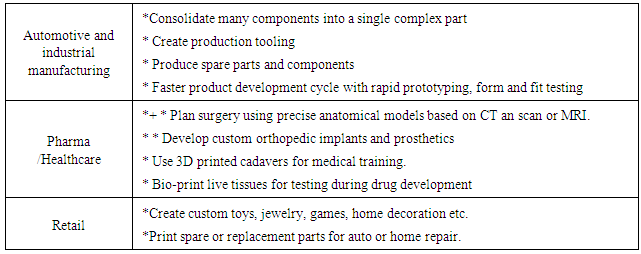
Basically, 3D printing technology has been developed by Silicon Valley start-up, Carbon3D Inc., enables objects to rise from a liquid media continuously rather than being built layer by layer as they have been for the last several years, representing a fundamentally new approach to 3D printing [1]. 3D is also known as rapid manufacturing or rapid prototyping printing process, which has ability to make efficient use of raw materials and produce minimal waste while reaching satisfactory geometric accuracy [2-3]. Using this method, a design in the form of a computerized 3D solid model can be directly transformed to a finished product without the use of additional fixtures and cutting tools. These open the possibility of producing parts with complex geometry which are difficult to obtain using material removal processes. In addition, 3D printing is ability to construct complex geometries means that many previously separated parts can be consolidated into a single object [4].
The 3D software digital slice model is utilized for final model into hundreds or thousands of horizontal layers. When the sliced file is uploaded in a 3D printer, the object can be obtained layer by layer. The 3D printer reads every slice or 2D image and creates the object, blending each layer without visible of any sign of the layers, with as a result the three dimensional object. The 3D printing is applicable for different sectors as mentioned in Table-1. Generally, many different printing technologies are material dependents.
Table 1. Emerging uses of 3D printing in the different industry sectors [5]
     

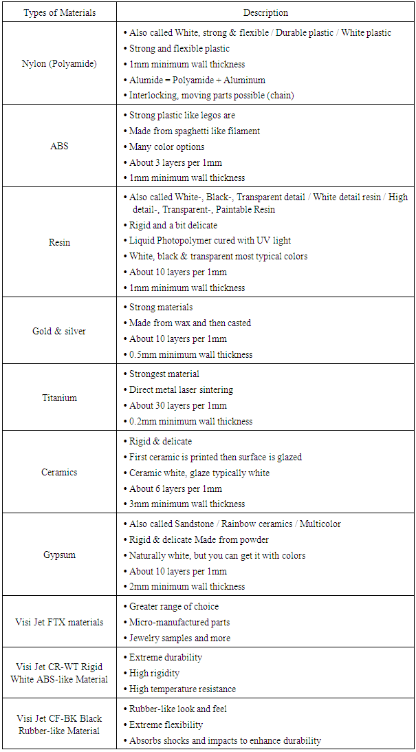
2. 3D Printing Materials

3D printing has emerged as a leading manufacturing technology all over the world. The development of new method does not affect only quality of the end product but it also opens new markets and influences on the price of used materials. The success of 3D printing is depended on fine-tuning materials to the needs of each application. This fine-tuning process is involved on the type and the quality, strength and costs of materials. There are many materials that can select when it comes to 3D printing. However it’s often tough to decide on the right one. The various materials can be adopted for 3D printing based on the needs of market.
The types of materials are listed in Table-2 [5]. There are many materials that can be used for 3D printing depending on their application. The thermoplastics materials ABS and PLA are soft and moldable when heated and return to a solid after cooling. This process can be repeated several times and their ability to melt again to processed further. However, there are many thermoplastics in which very few of them are currently used for 3D Printing. The best 3D printing materials, which has to pass three different tests; initial extrusion into Plastic Filament, second extrusion and trace-binding during the 3D Printing process, then finally end use application. The ABS and PLA is the best materials if before use or when stored long term, they are sealed off from the atmosphere to prevent the absorption of moisture from the air. This does not mean plastic will be ruined by a week of sitting on a bench in the shop, but long term exposure to a humid environment can have affects the printing process and to the quality of finished parts. Varieties of ABS, PC and high performance materials are available in the market likes ABS Plus, ABSi, ABS-M30, ABS-30i, ABS-ESD7, ASA, PC, Pc-ABS, PC-ISO, PPSF/PPSU, ULTEM1010, ULTEM9085 and nylon12 [6].
Table 2. Different materials and properties [5]
     

3. Manufacturing Process of 3D Printings

The American Society for Testing and Materials group ASTM-F42 have developed a set of standard method that classify the additive manufacturing (AM) processes into seven categories according to Standard Terminology for Additive Manufacturing Technologies.

3.1. Vat Photo Polymerization

3D printer is based on the Vat Photo polymerization method in which container filled with photopolymer resin and then hardened with UV light source as shown in Fig.1.
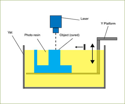
Figure 1. Photo Vat Polymerization method [6]
The most commonly used technology in this method is Stereo lithography (SLA). This technology employs a vat of liquid ultraviolet curable photopolymer resin and an ultraviolet laser to build the object’s layers one at a time. For each layer, the laser beam traces a cross-section of the part pattern on the surface of the liquid resin. With the exposure of ultraviolet laser light, cures and solidifies the pattern traced on the resin and joins it to the layer below. After the pattern has been traced, the SLA’s elevator platform descends by a distance equal to the thickness of a single layer, typically 0.05 mm to 0.15 mm (0.002″ to 0.006″). Then, a resin-filled blade sweeps across the cross section of the part, re-coating it with fresh material. On this new liquid surface, the subsequent layer pattern is traced, joining the previous layer. The complete three dimensional objects are formed by this process. Stereolithography requires the use of supporting structures which serve to attach the part to the elevator platform and to hold the object because it floats in the basin filled with liquid resin. These are removed manually after the object is finished [6].

3.2. Material Jetting

In this process, material is applied in droplets through a small nozzle, similar to the way a common inkjet paper printer works, but it is applied layer-by-layer to a build platform making a 3D object and then hardened by UV light. Then, we can see presentation of Stratasys’ Objet 500 Connex 3D printers that use their proprietary Triple-Jetting technology and can clearly identify (Fig.2) the print heads and UV light [7].
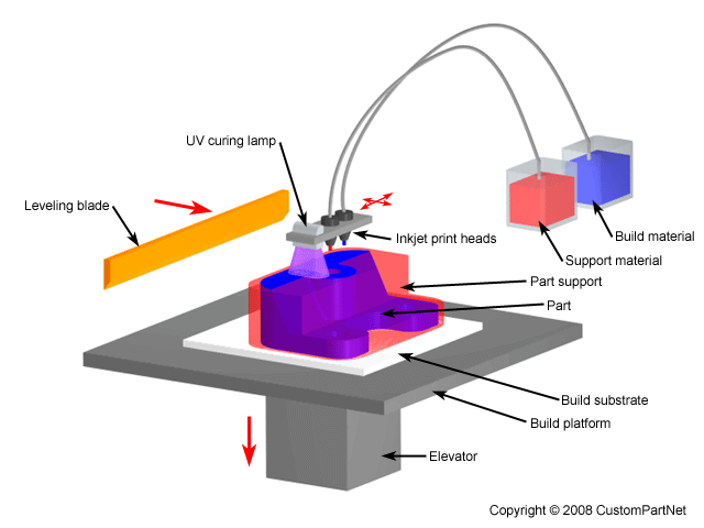
Figure 2. Material Jetting schematics. Image source [7]

3.3. Binder Jetting

Two materials (likes powder base material and a liquid binder) are used in the binder jetting method at a time. The powder is spread in the build chamber in equal layers and binder is applied through jet nozzles that “glue” the powder particles in the shape of a programmed 3D object as shown In Fig.3.
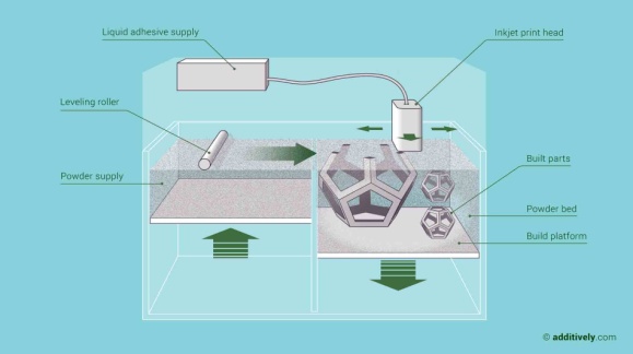
Figure 3. Binder jetting 3D printing technology overview. Image source [7]
The finished object is “glued together” by binder remains in the container with the powder base material. After the print is finished, the remaining powder is cleaned off and used for 3D printing of next object. This technology was first developed at the Massachusetts Institute of Technology in 1993 and in 1995 Z Corporation obtained an exclusive license [7].
The technology of binder jetting is used for plastic material or sand to create precise casting models or casting cores as well as for creating illustration models for architecture. Poor stability and high porosity of the parts are big issue of this technology. In case of the plastic material PMMA (poly-methylmeth-acrylat), the binder reacts with the powder and solidifies the printed areas. Afterward, the parts have to stay in the powder-bed for 24 hours until they can be unwrapped. The tensile strength of these parts was measured to be about 4.5 MPa; a post-treatment by infiltrating the part with wax or epoxide resin is possible and raises the tensile strength to 28 MPa. Due to the solidification, the accuracy of this technology is not accurate compare to laser beam. The binder jetting technology has a high potential for an efficient production of parts. One disadvantage is the low density of the parts. To enlarge the field of application for this technology, the manufacturing system was extended by integrating different functions [7].

3.4. Material Extrusion

The Fused deposition modeling (FDM) method is commonly used in 3D process. The FDM technology is working by the use of plastic filament or metal wire in unwound from a coil and supplying material to an extrusion nozzle, which can turn the flow of material on and off. The nozzle is heated to melt the material and can be moved in both horizontal and vertical directions by a computer-aided manufacturing (CAM) software package. The details are mentioned in Fig.4. The object is produced by extruding melted material to form layers as the slowly material hardens after extrusion from the nozzle. This technology is commonly used with two plastic filament material types: ABS (Acrylonitrile Butadiene Styrene) and PLA (Polylactic acid) but many other materials are available ranging in properties from wood filed, conductive, flexible etc. FDM was invented by Scott Crump in the late 80’s and was commercialized in 1990 [8]. Stepper motors or servo motors are typically employed to move the extrusion head. The mechanism used is often an X-Y-Z rectilinear design, although other mechanical designs such as deltabot have been employed. Although as a printing technology FDM is very flexible, and it is capable of dealing with small overhangs by the support from lower layers. The software that comes with this technology automatically generates support structures if required. The machine dispenses two materials, one for the model and one for a disposable support structure. The term fused deposition modeling and its abbreviation to FDM are trademarked by Stratasys Inc.
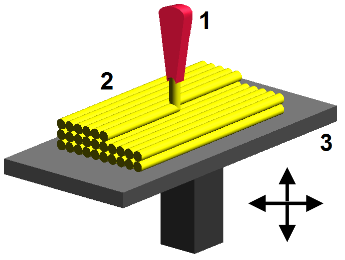
Figure 4. Fused deposition modelling (FDM), a method of rapid prototyping: 1 – nozzle ejecting molten material (plastic), 2 – deposited material (modelled part), 3 – controlled movable table. Image source: Wikipedia, made by user Zureks under CC Attribution-Share Alike 4.0 International license [8]

3.5. Powder Bed Fusion

The most commonly used technology in the 3D processes is Selective laser sintering (SLS) and it is also known powder bed fusion method. An SLS printer is used for powdered material as the substrate for printing new objects. This technology uses a high power laser to fuse small particles of plastic, metal, ceramic or glass powders into a mass that has the desired three dimensional shapes. The laser source fuses the powdered material by scanning the layers generated by the 3D modeling program on the surface of a powder bed. After each cross-section is scanned, the powder bed is lowered by one layer thickness.
Then a new layer of material is applied on top and the process is repeated until the object is completed. All untouched powder remains as it is and becomes a support structure for the object. The schematic picture is given in Fig. 4. Therefore there is no need for any support structure which is an advantage over SLS and SLA [9, 10].

3.6. Sheet Lamination

Sheet lamination involves material in sheets which is bound together with external force. Sheets can be metal, paper or a form of polymer. Metal sheets are welded together by ultrasonic welding in layers and then CNC milled into a proper shape as can be seen in Fig.5. Paper sheets can be used also, but they are glued by adhesive glue and cut in shape by precise blades [9].
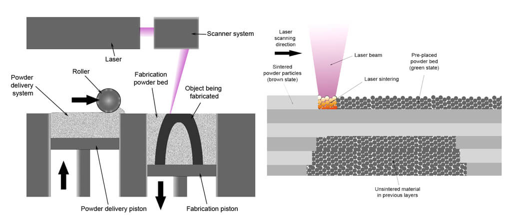
Figure 5. SLS system schematic. Image source [11]

3.7. Thermal Inkjet Printing

Inkjet printing is a “noncontact” method that uses thermal, electromagnetic, or piezoelectric technology to deposit tiny droplets of “ink” (actual ink or other materials) onto a substrate according to digital instructions. In thermal inkjet printing (TIJ), droplet deposition is usually done by using heat or mechanical compression to eject the ink drops. In TIJ printers, heating the print head creates small air bubbles that collapse, creating pressure pulses that eject ink drops from nozzles in volumes as small as 10 to 150 picoliters. Droplet size can be varied by adjusting the applied temperature gradient, pulse frequency, and ink viscosity. TIJ printers are particularly promising for use in tissue engineering and regenerative medicine. Because of their digital precision, control, versatility, and benign effect on mammalian cells, this technology is already being applied to print simple 2D and 3D tissues and organs (also known as bioprinting). TIJ printers may also prove ideal for other sophisticated uses, such as drug delivery and gene transfection during tissue construction [11].

3.8. Directed Energy Deposition

This process is used in the high-tech metal industry and in rapid manufacturing applications. The 3D printing apparatus is usually attached to a multi-axis robotic arm and consists of a nozzle that deposits metal powder or wire on a surface and an energy source (laser, electron beam or plasma arc) that melts it, forming a solid object as shown in Fig.6 [12].
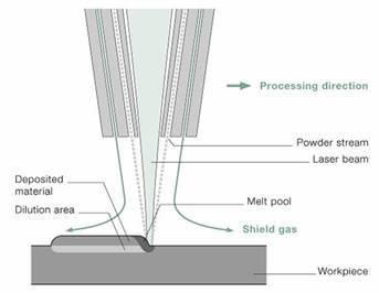
Figure 6. Direct Energy Deposition with metal powder and laser melting [12]

4. Development of 3D Printing Materials

4.1. Metal Particles Filled ABS Material

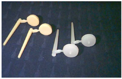
A new metal/polymer composite material is successfully produced and tested for direct rapid tooling application using the FDM rapid prototyping process. Characterization of this new material displays desirable mechanical properties, offering fabrication of flexible feed stock filaments for producing functional parts and tooling directly on the FDM system [13]. These properties can help to establish the upper limits for the process ability of filament of composites in terms of the particle size and the volume fraction of filler content. In the initial stages of FDM processing, there are a few problems related to filament size variation, over filling with material, clogging of the nozzle and delamination of a few layers due to presence of plasticizer. However, these problems can overcome by making more uniform filaments, regulating the amount of plasticizer, and selecting appropriate values of slice thickness, road width, fill patterns and nozzle diameter. In the initial trials, the build time of a part built with this new composite is almost twice of the time taken in building the same part with the P301 nylon material used in the FDM machine as shown in Figure 7. Also, the tool used in additive manufacturing (AM) to rapidly create three-dimensional models is a fully developed technique and capable of fabricating multifunctional devices.
Figure 7. A complex shaped injection moulding insert produced on FDM [13]
The AM process has undergone significant advancements in recent years. One driving force of significant innovation has been the hybridization of AM with other manufacturing techniques such as direct write (DW), where conductive and insulating materials are deposited enabling the creation of “structural” electronics. David et al 2015 [14] carried out that the rheological differences are altered the deposition characteristics as compared to ABS and allowed for the printing of smoother planes. The blend is also proven to be an enabler for the improvement of anisotropy by decreasing the difference in ultimate tensile strength (UTS) between samples fabricated in the XYZ and ZXY print directions as shown in Figure 8.
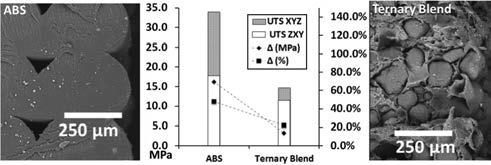
Figure 8. The rheological differences of the ternary blend as compared to ABS obscure the print rasters leading to a decrease in build orientation-caused mechanical property anisotropy [14]
Large number of papers is published to characterizing of titanium alloys as used in electron beam melting and selective laser melting (Murr et al., 2009, 2011, 2012 [15-17]. Also, many work are describing the characterization of acrylonitrile butadiene system (ABS) for use in fused deposition modeling (FDM) system (Ahn et al 2002, Torrado Perze et al 2014a [18-20]). Applications include design visualization, prototyping, metal casting, architecture, education, geospatial, healthcare and entertainment / retail., replicating ancient and priceless artifacts in archaeology, reconstructing.
It is also observed that FDM produced inserts composite (made of iron/nylon) is take less time and injection pressure when compared to the times and injection pressures used by Direct AIM inserts produced by the SLA method [21]. The FDM required only 35s of cycle time with an injection pressure of 2.62 MPa for the ABS parts, while the direct ACES injection moulding (AIM) inserts required 5 min of cycle time and an injection pressure of 22 MPa for the ABS parts of similar dimensions. Similar observations occur in case of parts injected in LDPE plastics as shown in Fig. 9.
Figure 9. ABS (left two) and LDPE (right two) parts produced on injection moulding machine using FDM made inserts [21]
Also, iron particles filled ABS and copper particles filled ABS is successfully developed for direct application in Fused Deposition Modeling rapid prototyping process. The flexible filaments of the new composite material are produced to fabricate the parts. Due to highly metal particles filled matrix composite material, injection tools and inserts made using this material on Fused Deposition Modeling, will demonstrate a higher stiffness comparing to those made out of pure polymeric material resulting in withstanding higher injection moulding pressures. Stiffness of all composites dramatically drops as the temperature approaches the glass-transition temperature, whereas matrix polymer transforms from solid state into semi-liquid or glassy state, and therefore due to higher free volume available, it suppresses any potential for interlocking of polymer and filler particles. Fig.10 clearly indicates the differences in between the storage modulus and loss modulus with the variation of temperature of 10% iron filled and filled ABS [22].
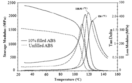
Figure 10. Comparison of dynamic mechanical properties of virgin ABS and 10% iron-powder filled ABS [22]
The iron powder reinforced nylon matrix is used in FDM process for prototyping process. This will reduce the cost, thermal and mechanical properties. The thermal conductivity of the iron powder filled nylon matrix composite is increasing with increasing of iron powder. This indicates that the iron fillers have a higher probability to form conductive particle chains in the matrix as shown in Fig.11.
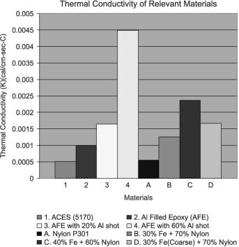
Figure 11. Thermal conductivity values for various materials [23]
The free electrons are believed to be hopping across the gap between the particles. This is effective in enhancing the heat transfer within the nylon matrix. The figure shows the thermal conductivity depend on the materials [23]. The 3D micro-batteries are composed with high aspect ratio of electrodes in interdigitate architectures. Careful design of concentrated Li4Ti5O12 (LTO) and LiFePO4 (LFP) viscoelastic inks enabled printing of these thin-walled anode and cathode structures. This 3D interdigited micro-battery architecture (IMA) have very high areal energy density of 9.7 J cm-2 at a power density of 2.7 mW cm-2. This type of micro-batteries may find potential application in autonomously powered microelectronics and biomedical devices [24].

4.2. Fibre/Nano Filled ABS Material

Most of the material likes, metal, ceramic and carbon nanomaterials are frequently used into AM technologies such as stereo lithography, laser sintering, fused filament fabrication, and three-dimensional printing. The addition of nanomaterials into the printing media for additive manufacturing affects significantly the properties of the final parts. Therefore, it is limitation of nanomaterials in the area of 3D printing by AM method [25]. However, the ability to ceramic materials in 3D printing is critical for structural, functional, and biomedical applications. The best approach is direct ink writing (DIW), in which 3D structures are built layer by layer through the deposition of colloidal or polymer based inks [26]. This method allows one to design and rapidly fabricate ceramic materials in complex 3D shapes without the need for expensive approach.
Whereas, the small amount of short glass fibre (4 mm in length) reinforced ABS composite is also significantly improves the strength of an ABS filament at the expense of reduced flexibility and handle ability during FDM process [27]. Short carbon fiber (3.2 mm in length) reinforced ABS resin feedstock at different fiber loadings is prepared, and these feedstock materials are used to successfully fabricate composite specimens by both the FDM printing and compression molding (CM) processes. The comparison between tensile strength and elastic modulus of ABS-CF composites by CM and FDM processes are shown in Fig.12.
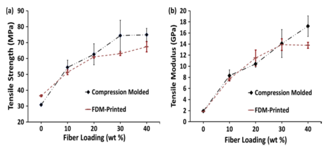
Figure 12. Effect of fiber content and preparation process on (a) tensile strength, and (b) modulus, of ABS/CF composites [28]
The results indicate that the average fiber length significantly dropped in both processes, due to high shear mixing step during compounding [28]. Under this process, no visible porosity and voids are observed in CM samples, only porosity is observed in FDM printed samples. With increase of fiber content, voids inside the FDM printed beads increased, whereas voids between the beads decreased. FDM printed specimens have high fiber orientation in the printing direction, approaching perfect alignment with the beads. The FDM process with its controlled orientation and good dispersion capabilities, along with the use of short carbon fiber reinforced feedstock, has great potential for the manufacturing of load bearing composite systems. FDM process is also improving the interfacial adhesion between fibres and matrix appears to be full potential of FDM process in 3D printing [29].
The inter-particle interactions are affected the phase behavior of 3D structure and rheological properties of microsphere nanoparticle mixtures. Negligibly charged microspheres are flocculate, when suspended alone undergo a remarkable stabilizing transition upon the addition of highly charged nanoparticles. The formation of a dynamic nanoparticle induces an effective repulsion between the microspheres that promotes their stability. The increase of nanoparticle concentration, the colloids again undergoes flocculation because of the emergence of an effective microsphere attraction, whose magnitude exhibits a quadratic dependence on the concentration of nanoparticles [30]. Single-walled carbon nanotubes (SWCNTs) and vapor grown carbon fibers (VGCFs) are compounded with poly (acrylonitrile-co-butadiene-co-styrene) (ABS) to create new class of composites for use with Extrusion Freeform Fabrication (EFF) process. The VGCF and SWCNTs reinforced composites processed by EFF displayed improved tensile modulus compared to similarly processed ABS and composite material with the fiber orientation, and the SWCNT reinforced material are displayed the highest strength and modulus (Shown in Fig. 13) with high dispersion and distribution of fibers in the matrix without porosity.
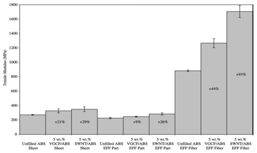
Figure 13. Variation of tensile modulus versus modifies composites [31]
Also, multi-walled carbon nanotubes (MWCNTs) is useful for 3D printing structure and shows better dispersion with yarn reinforced components [31].
The fracture behavior shows that the improved stiffness resulted from the increased resistance to chain mobility in the polymer caused by the addition of VGCFs. FDM process optimization and further fiber treatment to give better short carbon fiber/matrix adhesion could increase the ductility of the composite and lead to larger mechanical property increases. The VGCF reinforced ABS composite possessed a storage modulus 68% greater, on average, than that of the unfilled ABS at 40°C [32, 33]. When, additive manufacturing process is used for the multifunctional nanocomposite materials, this leads to 3D printing capability with greater control of material properties and thickness. Therefore, better properties will achieved with the reduced weight [34]. Stratasys FDM is a typical Rapid prototyping (RP) process that can be fabricated prototypes out of ABS plastic. From FDM ABS (P400) process, it is very easy to control the air gap and raster orientation effect on the tensile strength of an FDM part greatly as shown in Fig. 14. Bead width, model temperature, and color have little effect. The measured material properties showed that parts made by FDM have anisotropic characteristics and dependent on the raster direction [35].
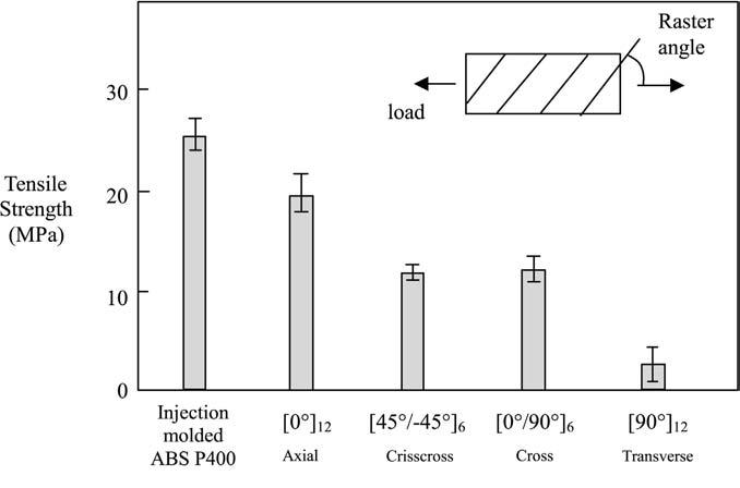
Figure 14. Tensile strength of specimens with various raster (zero air gap) compared with injection molded ABS P400 [36]
The digital projection printing method is effectively used to print 3D microstructures with efficient piezoelectric nanoparticle polymer composite materials. A piezoelectric polymer is fabricated by incorporating barium titanate (BaTiO3, BTO) nanoparticles into photoliable polymer solutions such as polyethylene glycol diacrylate and exposing to digital optical masks. This could be dynamically altered to generate 3D microstructures. To improve the mechanical to electrical conversion efficiency of the composites, the BTO nanoparticles are chemically modified with acrylate surface groups, which formed direct covalent bond with the polymer matrix under light exposure [36].

4.3. Effect of Variation in Deposition on FDM

FDM models are able to develop the layer thickness, deposition angle and roughness. The quantitative analysis regards the bench marking studies which compare the FDM and other AM technologies. It originates from a geometrical model of the filament which takes into account the radius and the spacing of the profile section. The model shows that the dimensional deviation is pair to zero for the vertical walls, as demonstrated in a preliminary experimentation and it increases for deposition angles less and greater than 90°. The validation has been performed by a specimen designed for the purpose in order to investigate 60 different deposition angles in the range 0–180° as shown in Fig.15 [37].
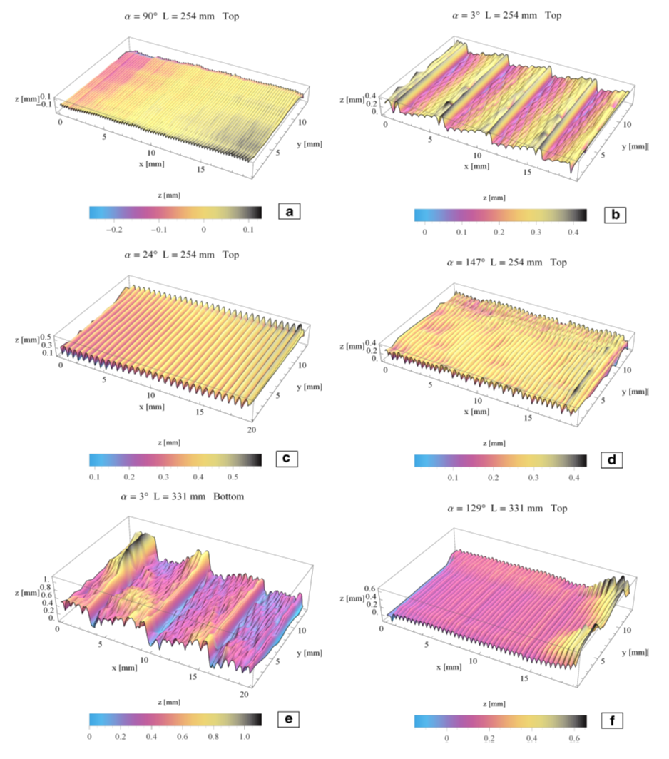
Figure 15. Three dimensional maps of specimen surface of different deposition angle and layers [37]
The FDM printer is also producing significant artifacts when filament streams are not long and continuous, this is due to the rate at which the printer can start and stop the flow of melted filament. This approach should require incessant switching between print heads, increasing the total printing time significantly. The geometric fidelity of 3D printer is very high and still on the way to full color printing at the consumer level. Recently low end printers with two color heads are arrived in the market, and demonstrated how they can produce interleaved color patterns necessary to print two-tone images. With the passive color mixing technique one can achieve a greater perceived color space and can print two-tone texture mapped objects [38]. The FDM method is print with different orientations and raster anglesto achieve the desired properties of the model, while shortening the manufacturing times due to maintenance costs. If, select five different raster angles (0°, 30°, 45°, 60° and 90°) for three part orientations (horizontal, vertical and perpendicular), surface roughness, tensile strength and flexural strength are affected due to change of surface roughness. The surface roughness changes with the different position are marked in Fig. 16 [39]. The mechanical properties of ABS monofilament and the in-plane properties of FDM ABS materials with three microstructures are significantly influence on the stress-strain response. The elastic modulus values 11 to 37 per cent lower and strength values 22 to 57 per cent lower than the ABS monofilament. The highest stiffness and strength values are found for loading in the fiber extrusion direction on an aligned microstructural configuration with a small negative fiber-to-fiber gap setting. The strength values for both the monofilament and FD materials increased logarithmically with strain rate [40].
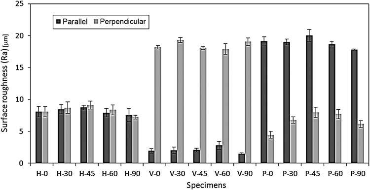
Figure 16. Showing roughness in parallel and perpendicular direction [39]
The FDM is also used to generate layers by the use of biodegradable materials. The Polylactic acid (PLA) and tricalcium phosphate (TCP) composite is state of art material in the tissue engineering and maxillofacial surgery. The influence of the parameters of FDM on pore distribution and processing conditions are affects the crystallinity of the implant and subsequently effects on the degradation behavior and time. The DSC result is indicate that each stage of the process from granulate, extrude and component after processing in the FDM machine. The glass transition temperature is between 54 and 568°C and decreases slightly with each processing step [41]. The material extrusion 3D printing (ME3DP) is developed for multiple blends of acrylonitrile butadiene styrene (ABS), styrene ethylene butadiene styrene (SEBS), and ultrahigh molecular weight polyethylene (UHMWPE). They are created through a twin screw compounding process to produce novel polymer blends compatible with ME3DP platforms. In comparison, polymeric elastomers like SEBS have low viscosity, low process temperature, and low distortion during the extrusion. Also, SEBS is resulted high impact strength and high elongation. Due to this behaviour, blended system of SEBS and ABS is increases the elastomeric properties and toughness of ABS. Also, by incorporating a combination of SEBS and UHMWPE to ABS, it achieved the benefits of UHMWPE (toughness) with the properties of ABS and SEBS (printability and relatively low process temperature) [42].
Layered manufacturing (LM) is a rapid prototype (RP) technique in which a part is fabricated by stacking layer by layer. FDM is a LM technique where the layers are fabricated on an evolutionary fashion using deposition of roads in a “restoring” configuration. The properties of thepart depend on the orientation and path, which is critical when FDM process is used to for the end use [43]. The FDM process is also used to manufacture rapid prototypes printing with textured surface. This is another bench marking of rapid prototyping systems. The Fig. 17 shows the selected regions and textured surface with alternative directions. Visual inspection clearly indicates that the same condition is associated with the textured appearance due to stair-stepping [44]. During the formation of extruded polymer filament in the FDM process, the bonding phenomenon is thermally driven and ultimately changes the mechanical properties of the resultant prototypes. The cooling temperature profiles have large effect on the interface bond strength between filaments [45].
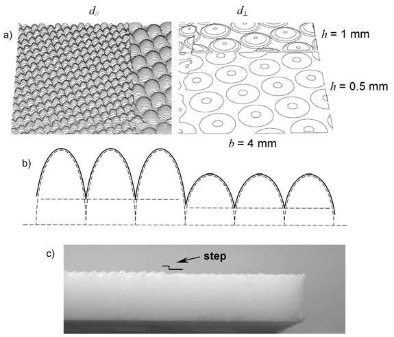
Figure 17. Resolution limits: (a) spacing of layer contours; (b), (c) feature sinking [44]
The interface behavior of micro layered deposited by FDM process for RP materials and examined by high impact velocity. The critical energy release rate at fracture initiation for the RP material ABS shows that higher striker velocities, delamination effect is more prominent. This is responsible for more crack propagation energies. The micro layered ABS in RP proved a better material to absorb fracture energy during impact loading compared to the commercially available monolithic ABS material [46]. A multi material technology FDM system is also developed to construct the production of parts using either discrete multi materials or the build process variation with layers and width. Two legacy FDM machines is installed onto a single manufacturing system to allow the strategic, spatially controlled thermoplastic deposition with multiple extrusion nozzles of multiple materials during the same build. This automated process is enabled by the use of a build platform attached to a pneumatic slide that moved the platform between the two FDM systems, which control the system. This will improve the surface roughness of materials [47]. The generation of multi-material technology is often involved printing of individual materials using multiple nozzles. The drawbacks of printing one material at a time are to carefully align each nozzle as well as start and stop ink flow on demand without introducing defects [48]. Although, the tensile strength of FDM ABS is relatively close to the bulk material, up to 80 percent and its ability to absorb energy before fracture. This indicates the improvement in absorbing capacity. FDM ABSplus (P430) material properties are more isotropic than the predecessor, ABS (P400). The ABSplus fractures in the order of thousands of cycles at 40 percent of ultimate stress load, while the ABS exhibits the similar cycle limits at 60 percent of its ultimate stress load [49]. The FDM process can be modify with the parameters such as build orientation, raster angle (RA), contour width (CW), raster width (RW), and raster-to-raster air gap (RRAG), which improve the ultimate tensile strength (UTS), Young’s modulus, and tensile strain. The building parameters (including build orientation, RA, RW, CW, and RRAG) are contributed to the resulting mechanical properties of FDM produced parts as shown in Fig. 18.
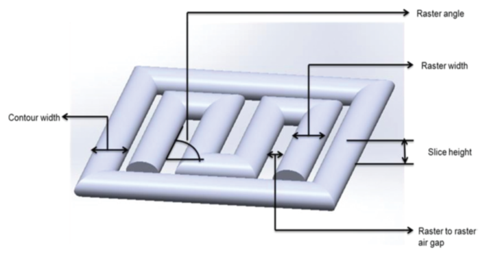
Figure 18. FDM building parameters [50]
If the RRAG is decreased from zero, a negative air gap is appeared, which resulting in partially over lapping rasters [50]. The visual feedback method improved the ultimate tensile strength with the introduction of negative RRAGs, leading to average increases in strength of 16%, 7%, and 22% for XYZ, XZY, and ZXY build orientations, respectively (Fig.19). The cellularlattices are fabricated by FDM process. Fig. 20. (a) and (b) shows fabricated cellular lattice structures and a close view of the struts and joints.
Figure 19. Build orientations used for the fabrication of ASTM D638 type I specimens [51]
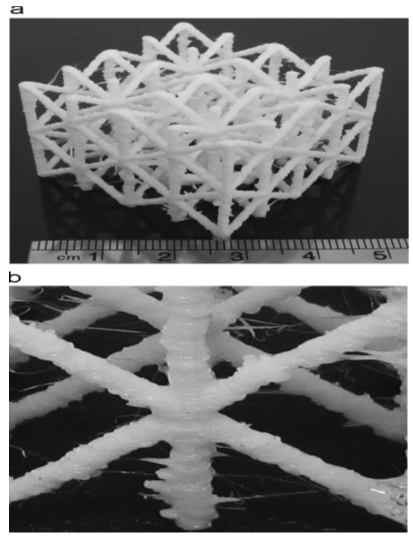
Figure 20. (a) APLA cellular lattice structure fabricated by FDM (b) a close view of CLS's struts and joints [51]
The structure is made layer by layer sothat the diameter may be different from one layer to another. The elastic modulus is obtained under compression andthe collapse stress of the lattice. Thestruts diameter is measured in several points of each strut, and the probability of the diametersis measured to obtain the bulk material parameters [51]. However, analysis is also required to characterize the fiber composites, appear to be helpful in understanding the mechanical behavior of FDM materials. The tensile strength of FDM polycarbonate is depended on the raster angle. The material is found to be highly dependent of fibre orientation [52]. The surface profile is directly affected on the FDM part accuracy in Z dimension. This result shows that the accuracy in the Z dimension of an FDM can increase by improving the surface quality of the support base. When built using the modified configuration as shown in Fig. 21(a) and (b), the top of the support base had a large regular surface. The effect of the support walls can, with some effort, still be seen, but is much reduced. There are no deep valleys in the default configuration, and the cohesion between adjacent filaments is better, as expected, the bottom surface of the model as seen in Fig.21 (c) and (d) is smoother [53].
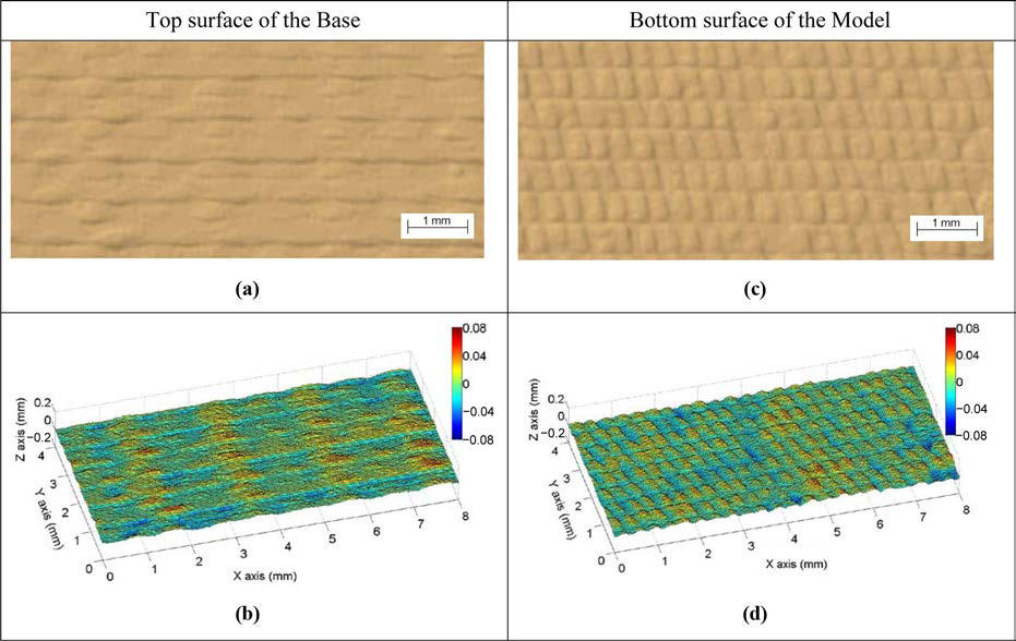
Figure 21. Scanned images of the top surface of the base (a and b) and bottom surface of the model (c and d) using the modified configuration [53]
3D printing techniques is very much useful for a small wireless sensor node. This volume filling approach ensures near optimal bandwidth performance of the small antenna which will increase the system’s battery life, data rate or range. The fabricated spherical antenna’s bandwidth efficiency is increased more than half of the fundamental limit and radiation pattern measurements exhibit a dipole pattern with −0.7 dBi gain [54].

4.4. 3D printing Application in Biomedical

Most of scientists are working to apply 3D printing technology to the field of medicine, which is most exciting area of research for dramatic changes in technology. However, 3D printing is much easier to print with plastic, metal, or chocolate than to print with living cells. In recent years, researchers have developed successful progress in building tissues and organ like structures in the laboratory. Computer added design and image processing are combined with computer-guided one and two-component air-driven 3D dispensing of hot melts, solutions, pastes, dispersions of polymers as well as monomers and reactive oligomers to produce solid objects with complex shapes and tailor-made internal structures. During the 3D plotting process either individual microdot are positioned in order to construct complex objects, fibers, tubes and scaffolds similar to non-woven. Plotting in liquid media with densities similar to that of the dispensing liquid eliminated the need for construction of temporary support structures [55].
Scaffolds are of great importance for tissue engineering because they enable the production of functional living implants out of cells obtained from cell culture. These scaffolds require individual external shape and well defined internal structure with interconnected porosity. Rapid prototyping (RP) method is able to produce such parts. Some RP techniques exist for hard tissue implants and soft tissue scaffolds need a hydrogel material. No bio-functional and cell compatible processing for hydrogels exists in the area of RP [56]. A key feature of this RP technology is the three-dimensional (3D) dispensing of liquids and pastes in liquid media. In contrast to conventional RP systems, mainly focused on melt processing, the 3D dispensing RP process can apply a much larger variety of synthetic as well as natural materials, including aqueous solutions and pastes, to fabricate scaffolds for application in tissue engineering. For the first time, hydrogel scaffolds with a designed external shape and a well-defined internal pore structure can be prepared by this RP process [57].
Three-dimensional fiber deposition (3DF) rapid prototyping technologyis successfully used to produce novel 3D porous Ti6Al4V scaffolds with fully interconnected porous networks and highly controllable porosity and pore size. The main feature of this technology is the 3D computer-controlled fiber depositing of Ti6Al4V slurry at room temperature to produce a scaffold, consisting of layers of directionally aligned Ti6Al4V fibers. The experimental results show how the parameters influence the structure of porous scaffold. The potential of this rapid prototyping 3DF system for fabricating 3D Ti6Al4V scaffolds with regular and reproducible architecture meeting the requirements of tissue engineering and orthopedic implants is demonstrated [58]. One of the main issues in tissue engineering is the fabrication of scaffolds that closely mimic the biomechanical properties of the tissues to be regenerated. Conventional method is not sufficiently suitable to control scaffold structure to modulate mechanical properties. The 3DF process showed great potential for tissue engineering applications because of the precision in making reproducible 3D scaffolds, characterized by 100% interconnected pores with different shapes and sizes [59]. The 3DFprocess allows for the development of metallic scaffolds with accurately controlled pore size, porosity and interconnecting pore size. The titanium alloy scaffolds with different structural properties, such as pore size, porosity and interconnecting pore size are implanted on the decorticated transverse processes of the posterior lumbar spine of 10 goats. The bone formation is monitor after 3, 6 and 9 weeks and the animals are sacrificed at 12 weeks after implantation. In vivo results showed that increase of porosity and pore size, and thus increase of permeability of titanium alloy implants positively influenced their osteoconductive properties [60, 61].
Anatomical scaffolds are fabricated from a patient-derived computerized tomography dataset, and compared to cylindrical and toroidal tubular scaffolds. Lewis rat tracheal chondrocytes are seeded on 3DF scaffolds and cultured for 21 days. Interestingly, a lower scaffold's pore volume and porosity resulted in more tissue formation and a better cell differentiation. Scaffolds are compliant and did not show any signs of luminal obstruction in vitro. These results may promote anatomical scaffolds as functional matrices for tissue regeneration not only to help regain the original shape, but also for their improved capacity to support larger tissue formation [62]. Biomaterials is also capable of efficient gene delivery by embedded cells provide a fundamental tool for the treatment of acquired or hereditary diseases. A major obstacle is maintaining adequate nutrient and oxygen diffusion to cells within the biomaterial. Design micro-/macroporous scaffolds to improve cell viability and drug delivery. Murine bone marrow-derived mesenchymal stromal cells (MSCs) genetically engineered to secrete erythropoietin (EPO) are seeded onto poly-l-lactide (PLLA) scaffolds with different micro-porosities. Over a period of 2 weeks in culture, an increase in cell proliferation and metabolic activity is observed with increasing scaffold micro-porosity. The concentration of EPO detected in supernatants also increased with increasing micro-porosity level [63].
In applying the concept of tissue printing for the development of vascularized bone grafts, the primary focus lies on combining endothelial progenitors and bone marrow stromal cells (BMSCs). The 3D printing is very much useful for fiber deposition with a plotting device, Bio-plotter, for the fabrication of spatially organized, cell-laden hydrogel constructs. The results indicate that cells survive the extrusion and that their subsequent viability is not different from that of unprinted cells. The applied extrusion conditions did not affect cell survival, and BMSCs could subsequently differentiate along the osteoblast lineage [64]. Embryonic stem (ES) cells are a potential source for cartilage tissue engineering because they provide an unlimited supply of cells that can be differentiated into chondrocytes. So far, chondrogenic differentiation of both mouse and human ES cells has only been demonstrated in two-dimensional cultures, in pellet cultures, in a hydrogel, or on thin biomaterials. Mouse ES cells readily under went chondrogenic differentiation in vitro in pellets, on bare scaffolds, in Matrigel, and in agarose, both as single cells and in EBs. The ES cells can be used as a cell source for cartilage tissue engineering [65].
Despite the periodical and completely interconnected pore network that characterizes rapid prototyped scaffolds, cell seeding efficiency remains still a critical factor for optimal tissue regeneration. The 3D scaffoldis fabricated by combining 3D fiber deposition (3DF) and electrospinning (ESP). The 3DF scaffold provides structural integrity and mechanical properties, while the ESP network works as a “sieving” and cell entrapment system at the extracellular matrix (ECM) scale. 3DFESP scaffolds enhanced cell entrapment as compared to 3DF scaffolds. Furthermore, the ESP surface topology also influenced cell morphology. Thus, the integration of 3DF and ESP techniques provide a new set of “smart” scaffolds for tissue engineering applications [66].
Scaffolds for tissue engineering of bone should mimic bone matrix and promote vascular ingrowth. Porous scaffolds of hydroxyapatite and isogeneic acellular dentin are implanted into the dorsal skinfold chamber of balb/c mice. Additional animals received perforated implants of isogeneic calvarial bone displaying pores similar in size and structure to those of both scaffolds. Angiogenesis and neovascularization as well as inflammatory leukocyte-endothelial cell interaction and microvascular leakage are analyzed over a 14-day time period using intravital fluorescence microscopy. Implantation of both hydroxyapatite and dentin scaffolds showed a slight increase in leukocyte recruitment compared with controls. This is associated with an elevation of microvascular permeability, which was comparable to that observed in response to isogeneic bone [67]. Dynamic cell culture of the scaffolds improved cell viability and decrease the time of in vitro culture when compared to statically cultured constructs. Optimizing culture conditions and scaffold properties could generate optimal tissue/constructs combination for cartilage repair [68]. Hydrogels with low viscosities is difficult to use in constructing tissue engineering (TE) scaffolds to replace or restore damaged tissue, due to the length of time it takes for final gelation to take place resulting in the scaffolds collapsing due to their mechanical instability. This process can allow to plotting the various materials into a media bath containing material of similar rheological properties which can be used to both support the structure as it is dispensed and also to initiate cross-linking of the hydrogel [68].
The scaffolds fabricated by rapid prototyping have very smooth surfaces, which tend to discourage initial cell attachment. Initial cell attachment, migration, differentiation and proliferation are strongly dependent on the chemical and physical characteristics of the scaffold surface. The surface is inscribed with nano- and micro-sized pores using three-dimensional (3D) plotting method with a chemical blowing agent to produce a surface-modified 3D scaffold. Cell cultures on the scaffolds demonstrated that chondrocytes interacted better with the surface-modified scaffold than with a normal 3D scaffold [69]. Magnetic scaffolds for bone tissue engineering based on a poly(ε-caprolactone) (PCL) matrix and iron oxide (Fe3O4) magnetic nanoparticles are designed and developed through a three-dimensional (3D) fiber-deposition technique. Furthermore, confocal analysis is undertaken to investigate human mesenchymal stem cell adhesion and spreading on the PCL/Fe3O4 nanocomposite fibers. The results suggest that nanoparticles mechanically reinforced the PCL matrix; the elastic modulus and the maximum stress increased about 10 and 30%, respectively. Confocal analysis highlighted interesting results in terms of cell adhesion and spreading. All of these results show that a magnetic feature could be incorporated into a polymeric matrix that could be processed to manufacture scaffolds for advanced bone tissue engineering and, thus, provide new opportunity in terms of scaffold fixation and functionalize [70]. Soy protein slurry has been successfully printed using the 3D Bioplotter to form scaffolds. This process involved measuring the mass extrusion flow rate of the slurry from the instrument, which is directly affected by the extrusion pressure and the soy protein slurry properties. Scaffold properties, including relative crosslink density, mass loss upon rinsing, and compressive modulus revealed that EDC cross-linked scaffolds are the most robust with moduli of approximately 4 kPa. Scaffold geometry (45° and 90° layer rotations) affected the mechanical properties for DHT and EDC crosslinked scaffolds [71].
The bioactivity of sol–gel synthesized poly(ε-caprolactone) (PCL)/TiO2 or poly(ε-caprolactone)/ ZrO2 particles is already known. The potential of 3D fiber-deposition technique to design morphologically controlled scaffolds consisting of PCL reinforced with PCL/TiO2 or PCL/ZrO2 hybrid fillers is improved the properties of scaffold material [72]. Tooth-supporting periodontium forms a complex with multiple tissues, including cementum, periodontal ligament (PDL), and alveolar bone. A single stem/progenitor cell population appears to differentiate into putative dentin/cementum, PDL, and alveolar bone complex by scaffold's biophysical properties and spatially released bioactive cues [73]. Bioplotting is an emerging freeform scaffold fabrication technique useful for creating artificial tissue scaffolds containing living cells. Simultaneous maintenance of scaffold structural integrity and cell viability is a challenging task. General bioplotting method is more sophisticated alginate/hyaluronic acid scaffolds and can be fabricated with the inclusion of living cells into desired structures [74, 75]. Thin artificial tissues like trachea are grown from a patient’s own cells and it is already being used to treat patients. The scientists have shown that specific culture conditions can push stem cells to grow into self-organized structures resembling a developing brain, a bit of a liver, or part of an eye. All regenerative projects have run up against the same wall when trying to build thicker and more complex tissues like a lack of blood vessels. The 3D printed meta-materials with tunable are better mechanical properties which increase the tissue mimicking [76]. 3D printing technology is being used for most possible application in tissue engineering where organs and body parts are built using inkjet techniques. The construction of 3D engineered tissue is usually based on the mimic natural tissues and several key components cells, extracellular matrix (ECM), and vasculature which are useful to be patterned in precise geometries. Deposition of layers of living cells are generated onto a gel medium and gradually built up to form three dimensional structures [77]. Lewis’s group has developed novel 3D printing inks and nozzles that allow to precisely printing multiple materials for the development of tissue with blood vessels, as can be identified from Fig.22.
Figure 22. 3D printed images of tissue [79]
They have also used same approach to making the tubes inside kidneys that help filter blood. The group chose to focus on kidneys because they account for 80 percent of the need for organ transplants, and because a large numbers of patients die before ever receiving a replacement kidney [78].
Generally, lived tissues have high fracture toughness in order to withstand substantial internal and external mechanical loads. The high toughness of tissues needs to design with hydrogels capable for achieving similar toughness in order to withstand physiological mechanical loads. The fabrication of tough hydrogels often involves toxic chemical reactions. The biocompatible materials sodium alginate and poly (ethylene glycol) (PEG) are used to constitute an interpenetrating network. The resultant hydrogel of covalently cross linked PEG and ionically cross linked alginate to possesses high fracture toughness and allows cell encapsulation [79]. 3D micro-periodic scaffolds are composed of a gradient array of silk and hydroxyapatite (HA) filaments, which is fabricated by direct write assembly. This allows for precise control over the printed filament size and location within each scaffold. The 3D silk/HA scaffoldsare used to support the growth of co-cultures of human bone marrow derived mesenchymal stem cells (hMSCs) and human mammary microvascular endothelial cells (hMMECs) to assess in vitro formation of bone like tissue. The 3D scaffolds are novel method to get the effect of scaffold architecture and cell composition on human tissue formation [80]. 3D microperiodic hydrogel scaffolds is also offer a robust, biocompatible culture system for primary hippocampal neurons. The confocal microscopy and image analysis of cell-scaffold interactions shows the three dimensions neuronal development in complex 3D environments. These 3D in vitro studies revealed the formation of hippocampal neurons, as well as other sensitive cell types and tissues [81]. Also, researchers have used images of animals’ hearts to create models of the organ using a 3D printer. Then they built stretchy electronics on top of those models. The stretchy material can be peeled off the printed model and wrapped around the real heart for a perfect fit as shown in Fig. 23.
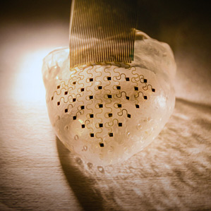
Figure 23. An array of sensors is embedded in a material designed to fit a beating heart perfectly [82]
The high density multi-parametric physiological mapping and stimulation are critically important in both basic and clinical cardiology. The 2D technology cannot cover the full epicardial surface or maintain reliable contact for chronic use without adhesives. Therefore, 3D elastic membranes shaped precisely to match the epicardium of the heart with the 3D printing. These devices completely envelop the heart, in a form-fitting manner, and possess inherent elasticity, providing a mechanically stable biotic/abiotic interface during normal cardiac cycles [82]. Due to the exceptional properties of graphene in electronics, energy storage and structural application, 3D printable graphene is applicable with the combination of graphene and polylactide-co-glycolide as a biocompatible elastomer. 3D printed liquid ink can be utilized under ambient condition via extrusion based 3D printing to create graphene structures with very small features less than 100 µm composed of two layers. The resulting 3D graphene material is mechanically robust and flexible while electrical conductivities greater than 800 S/m, an order of magnitude increase over reported 3D printed carbon materials. The medical test on human cadaver nerve model is indicated that the 3D graphene printing has exceptional properties and can be intra-operatively manipulated and applied to fine surgical procedures [83]. This could be applied toward the fabrication of functional electronics and biological devices as can be identified from Fig. 24.
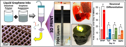
Figure 24. 3D graphene printing configuration [83]
The 3D bioprinting method is also fabricating engineered tissue constructs replete with vasculature, multiple types of cells, and ECM. Creating these heterogeneous structures requires the ability to precisely co-print the multiple structures. This new approach is very useful for creating vascularized, heterogeneous tissue constructions on demand based on 3D bioprinting [84]. 3D bioprinting is being used to regenerative medicine to fulfil the need for tissues and organs suitable for transplantation. This involves additional complexities compared with non-biological printing, likes choice of materials, cell types, growth and differentiation factors, and technical challenges related to the sensitivities of living cells and the construction of tissues [85]. 3D bioprinting is being usedorthopaedic surgeons to print artificial bone from a scan of the patient. The printing is exists with surgical materials to precisely the right shape to replace missing or damaged bone. The technique is recently used to create skull implants for people with head trauma and a titanium heel (Replicas of skull is shown in Fig.25) to replace heel bone that had been eaten away by cancer [86].
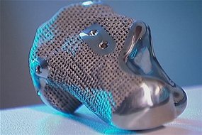
Figure 25. 3D bioprinting allows orthopaedic surgeons create titanium replicas to replace missing or damages bone [86]
The commercial nanoparticles for detoxification are often leads to accumulation in the liver, which increase the risk of poisoning especially in liver-failure patients. Therefore, liver-inspired three-dimensional (3D) detoxification device is created hydrogels printing with functional polydiacetylene nanoparticles installed in the hydrogel matrix. Then nanoparticles can attract, capture and sense toxins, while the 3D matrix with a modified liver lobule microstructure allows toxins to be trapped efficiently [87]. A 3D in vitro micro-chip (honeycomb branched structure) in hydrogel is created using 3D projection printing to understand the physical behavior and migration of cancer cells. The micro channels are preferably with the diameter of blood vessels [88]. Finally, 3D printing has become a useful and potentially transformative tool in a number of different fields, including medicine. As printer performance, resolution, and available materials have increased, so have the applications. Researchers continue to improve existing medical applications that use 3D printing technology [89].

5. Future Opportunities

The direct inkjet printing offers the ability to rapidly produce pattern of functional materials in complex 3D architectures from a broad array of materials. The 3D printing is drive towards patterning materials at finer length scales and faster printing speeds, which provides to use in many opportunities and challenges in medical sciences. The advances in 3D printing is gaining the importance in the field of medical engineering with new ink designs, better characterization and modeling of ink properties during deposition, and enhanced robotic-control and ink-delivery systems to allow 3D writing with greater precision and local composition specificity. The ability to locally specify both composition and structure is allowing even greater control over the properties and functionality of the resulting patterned materials.
3D printing is expected to play an important role in the trend toward personalized medicine, through its use in customizing useful products, organs, and drugs. 3D printing is being used commonly in pharmacy settings. The advanced 3D printing application is anticipated for bio-printing of complex organs. Although, due to challenges in printing vascular networks, the reality of printed organs is still some way off, the progress that has been made is promising. This is also expected that complex heterogeneous tissues, such as liver and kidney tissues will be fabricated successfully. This will be viable for live implants, as well as printed tissue and organ models for use in drug discovery. It may also be possible to print out a patient’s tissue as a strip that can be used in tests to determine the most effective drug. Also, it could even be possible to take stem cells from a child’s baby teeth for lifelong use as a tool kit for growing and developing replacement tissues and organs. False teeth, hip joints, replacement knees, potentially printable skin and organs will drive growth in the burgeoning market for 3D printers over the next decade.

ACKNOWLEDGEMENTS

The author would like to Department of Mechanical Engineering, Indian Institute of Technology (BHU), Varanasi-221005, India for their supports.

References

[1]  G.N. Levy, R. Schindel, J.P. Kruth, Rapid manufacturing and rapid tooling with layer manufacturing (LM) technologies: state of the art and future perspectives, CIRPAnn-ManufTechn 2003: 52:589–609.
[2]  J. Holmstrom, J. Partanen, J. Tuomi, M. Walter, Rapid manufacturing in the spare parts supply chain: alternative approaches to capacity deployment, J Manuf Tech Manag 2010: 21:687– 697.
[3]  S. Hasan, A. Rennie, The application of rapid manufacturing technologies in the spare parts industry. Solid Freeform Fabrication Symposium, University of Texas at Austin, USA, 2008: 584–590.
[4]  S. H. Huang, P. Liu, A. Mokasdar, L. Hou, Additive manufacturing and its societal impact: a literature review, Int J AdvManufTechnol 2013: 67:1191–1203.
[5]  H. Lipson, M. Kurman, Fabricated: The New World of 3D Printing, Wiley, Indianapolis 2013.
[6]  J. R. Tumbleston, D. Shirvanyants, N. Ermoshkin, R. Janusziewicz, A. R. Johnson, D. Kelly, K. Chen, R. Pinschmidt, J. P. Rolland, A. Ermoshkin, E. T. Samulski, J. M. DeSimone, Continuous liquid interface production of 3D objects, Science 2015: 20 (347): 1349.
[7]  J. Glasschroeder, E. Prager, M. F. Zaeh, Powder-bed-based 3D-printing of function integrated parts, Rapid Prototyping Journal, 2015: 21 (2): 207 – 215.
[8]  http://rpworld.net/cms/index.php/additive-manufacturing/rp-rapid-prototyping/fdm-fused-deposition-modeling-.html
[9]  H. Lipson, M. Kurman, Fabricated The New World of 3D Printing, Wiley, Indianapolis, 2013.
[10]  H.B. Hoy, 3D printing: making things at the library, Med Ref Serv Q 2013:32 (1):94–99.
[11]  X. Cui, T. Boland, D.D. D’Lima, M.K. Lotz, Thermal inkjet printing in tissue engineering and regenerative medicine. Recent Pat Drug Deliv Formul. 2012: 6(2):149–155.
[12]  J. M. Pearce, Building research equipment with free, open- source hard ware. Science 2012: 337: 1303–1304.
[13]  S.H. Masood, W.Q. Song, Development of new metal/polymer materials for rapid tooling using Fused deposition modelling, Materials and Design 2004: 25: 587–594.
[14]  D. Roberson, C. M. Shemelya, E. MacDonald, R. Wicker, Expanding the applicability of FDM-type technologies through materials development, Rapid Prototyping Journal 2015: 21 (2): 137 – 143.
[15]  L.E. Murr, K.N. Amato, S.J. Li, Y. X. Tian, X.Y. Cheng, S.M. Gaytan, E. Martinez, P.W. Shindo, F. Medina, R.B. Wicker, Microstructure and mechanical properties of open-cellular biomaterials prototypes for total knee replacement implants fabricated by electron beam melting, Journal of the Mechanical Behavior of Biomedical Materials2011 :4 (7): 1396-1411.
[16]  L.E. Murr, S.M Gaytan, D.A Ramirez, E. Martinez, J. Hernandez, K.N. Amato, P.W. Shindo, F.R. Medina, R.B. Wicker, Metal fabrication by additive manufacturing using laser and electron beam melting technologies, Journal of Materials Science & Technology, 2012: 28 (1): 1-14.
[17]  L.E. Murr, S.A. Quinones, S.M. Gaytan, M.I. Lopez, A. Rodela, E.Y. Martinez, D.H. Hernandez, E. Martinez, F. Medina, R.B. Wicker, Microstructure and mechanical behavior of Ti–6Al–4V produced by rapid-layer manufacturing, for biomedical applications, Journal of the Mechanical Behavior of Biomedical Materials 2009: 2 (1): 20-32.
[18]  S.H. Ahn, M. Montero, D. Odell, S. Roundy, P.K. Wright, Anisotropic material properties of fused deposition modeling ABS, Rapid Prototyping Journal,2002: 8 (4) 248-257.
[19]  A. R. Torrado Perez, D.A. Roberson, R.B. Wicker, Fracture surface analysis of 3D-printed tensile specimens of novel ABS-based materials, Journal of Failure Analysis and Prevention, 2014:14 ( 3) 343-353.
[20]  J. R. Tumbleston, D. Shirvanyants, N. Ermoshkin, R. Janusziewicz, A. R. Johnson, D. Kelly, K. Chen, R. Pinschmidt, J. P. Rolland, A. Ermoshkin, E. T. Samulski, J. M. DeSimone, Continuous liquid interface production of 3D objects, Science, 2015; DOI: 10.1126/science.aaa2397.
[21]  P. Jacobs, Recent advances in rapid tooling from stereolithography, In: Proceedings of Seventh International Conference on Rapid Prototyping, San Francisco, March 31–April 3, 1997: 338–54.
[22]  M. Nikzad, S.H. Masood, I. Sbarski, Thermo-mechanical properties of a highly filled polymeric composites for Fused Deposition Modeling, Materials and Design 2011:32: 3448–3456.
[23]  S.H. Masood W.Q. Song, Thermal characteristics of a new metal/polymer material for FDM rapid prototyping process", Assembly Automation, 2005: 25 (4) 309 – 315.
[24]  K. Sun, T.S. Wei, B. Y. Ahn, J. Y. Seo, S. J. Dillon, and Jennifer A. Lewis, 3D Printing of Interdigitated Li-Ion Microbattery Architectures, Adv. Mater 2013: 25: 4539–4543.
[25]  O. Ivanova, C. Williams, T. Campbell, Additive manufacturing (AM) and nanotechnology: promises and challenges", Rapid Prototyping Journal 2013: 19 (5) 353 – 364.
[26]  J. A. Lewis, J.E. Smay, J. Stuecker, J. Cesarano III, Direct Ink Writing of Three-Dimensional Ceramic Structures, J. Am. Ceram. Soc., 2006: 89 (12) 3599–3609.
[27]  W. Zhong, F. Li, Z. Zhang, L. Song, Z. Li, Short fiber reinforced composites for fused deposition modeling, Materials Science and Engineering A 2001:301:125–130.
[28]  H. L. Tekinalp, V. Kunc, G. M. Velez-Garcia, C. E. Duty, L. J. Love, A. K. Naskar, C. A. Blue, S. Ozcan, Highly oriented carbon fiber–polymer composites via additive manufacturing, Composites Science and Technology 2014:105: 144–150.
[29]  S.E. Bakarich, Three-Dimensional Printing Fiber Reinforced Hydrogel Composites. ACS Appl. Mater. Interfaces 2014: 6.18: 15998-16006.
[30]  S. K. Rhodes, J. A. Lewis, Phase Behavior, 3-D Structure, and Rheology of Colloidal Microsphere–Nanoparticle Suspensions, J. Am. Ceram. Soc. 2006: 89 (6): 1840–1846.
[31]  M.L. Shofner, F.J. Rodrı´guez-Macı´as, R. Vaidyanathan, E.V. Barrera, Single wall nanotube and vapor grown carbon fiber reinforced polymers processed by extrusion freeform fabrication, Composites: Part A 2003: 34: 1207–1217.
[32]  M. L. Shofner, K. Lozano, F. J. Rodrı´guez-Macı´as, E. V. Barrera, Nanofiber-Reinforced Polymers Prepared by Fused Deposition Modeling, Journal of Applied Polymer Science 2003: 89: 3081–3090.
[33]  J.M. Gardner, G. Sauti, J.W. Kim, R.J. Cano, R.A. Wincheski, C.J. Steller, B.W. Grimsley, D.C. Working, E.J. Stochi, 3D Printing of multifunctional carbon nanotube yarn reinforced components, Additive Manufacturing, 12, Pt-A, October 2016: 38-44.
[34]  T. A. Campbell, O. S. Ivanova, 3D printing of multifunctional nanocomposites, Nano Today 2013:8: 119—120.
[35]  S. H.Ahn,M. Montero D. Odell, S. Roundy, P. K. Wright, Anisotropic material properties of fused deposition modeling ABS, Rapid Prototyping Journal 2002: 8 (4): 248 – 257.
[36]  K. Kanguk, Z.Wei, Q. Xin, A. Chase, R. M. William, C. Shaochen, J.S. Donald, 3D Optical Printing of Piezoelectric Nanoparticle Polymer Composite Materials, ACS Nano 2014: 8 (10): 9799-9806.
[37]  A. Boschetto, L. Bottini, Accuracy prediction in fused deposition modeling, Int J AdvManufTechnol 2014: 73: 913–928.
[38]  T. Reiner, N. Carr, R.Mˇech, O. Št’ava, C. Dachsbacher, G. Miller, Dual-Color Mixing for Fused Deposition Modeling Printers, EUROGRAPHICS, 2014: 33 (2): 479-486.
[39]  I. Durgun, R. Ertan, Experimental investigation of FDM process for improvement of mechanical properties and production cost, Rapid Prototyping Journal 2014: 20 (3): 228 – 235.
[40]  J. F. Rodríguez James, J. P. Thomas, J.E. Renaud, Mechanical behavior of acrylonitrile butadiene styrene (ABS) fused deposition materials. Experimental investigation, Rapid Prototyping Journal 2001: 7 (3): 148 – 158.
[41]  D. Drummer, S. Cifuentes-Cuéllar, D. Rietzel, Suitability of PLA/TCP for fused deposition modeling, Rapid Prototyping Journal 2012: 18 (6): 500 – 507.
[42]  C. R. Rocha, A. R. T. Perez, D. A. Roberson, W.M. Keck, C. M. Shemelya, E. MacDonald, W.M. Keck, R. B. Wicker, Novel ABS-based binary and ternary polymer blends for material extrusion 3D printing, J. Mater. Res. 2014: 29 (17): 1859-1866.
[43]  A. Bellini, S. Güçeri, Mechanical characterization of parts fabricated using fused deposition modeling, Rapid Prototyping Journal 2003: 9 (4): 252 – 264.
[44]  A. Armillotta, (2006), Assessment of surface quality on textured FDM prototypes, Rapid Prototyping Journal 2006: 12 (1): 35 – 41.
[45]  Q. Sun, G.M. Rizvi, C.T. Bellehumeur, P. Gu, Effect of processing conditions on the bonding quality of FDM polymer filaments, Rapid Prototyping Journal 2008: 14: (2):72 – 80.
[46]  U. Ibrahim, M. A. Irfan, Dynamic crack propagation and arrest in rapid prototyping material, Rapid Prototyping Journal 2012: 18 (2) 154 – 160.
[47]  D. Espalin, J.A. Ramirez, F. Medina, R. Wicker, Multi-material, multi-technology FDM: exploring build process variations, Rapid Prototyping Journal 2014: 20 (3): 236 – 244.
[48]  J. O. Hardin, T. J. Ober, A. D. Valentine, J.A. Lewis, Microfluidic Printheads for Multimaterial 3D Printing of Viscoelastic Inks, Advanced Materials 2015:1-7.
[49]  J. Lee, A. Huang, Fatigue analysis of FDM materials, Rapid Prototyping Journal 2013:19 (4): 291 – 299.
[50]  M. S. Hossain, D. Espalin, J. Ramos, M. Perez, R. Wicker, Improved Mechanical Properties of Fused Deposition Modeling-Manufactured Parts Through Build Parameter Modifications, Journal of Manufacturing Science and Engineering, Transactions of the ASME, DECEMBER 2014: 136: 061002-1-12.
[51]  M. R. Karamooz Ravari, M. Kadkhodaei, M. Badrossamay, R. Rezaei, Numerical investigation on mechanical properties of cellular lattice structures fabricated by fused deposition modeling, International Journal of Mechanical Sciences, 88 (2014) 154–161.
[52]  N. Hill, M. Haghi, Deposition direction-dependent failure criteria for fused deposition modeling polycarbonate, Rapid Prototyping Journal 2014: 20 (3) 221 – 227.
[53]  N. Volpato, J. A. Foggiatto, D. C. Schwarz, The influence of support base on FDM accuracy in Z, Rapid Prototyping Journal 2014: 20 (3):182 – 191.
[54]  J.J. Adams, S.C. Slimmer, J.A. Lewis, J.T. Bernhard, 3D-Printed Spherical Dipole Antenna Integrated on Small Rf Node. Electronics Letters 2015:51 (9): 661-662.
[55]  Landers, Rüdiger, R. Mülhaupt, Desktop manufacturing of complex objects, prototypes and biomedical scaffolds by means of computer‐assisted design combined with computer‐guided 3D plotting of polymers and reactive oligomers, Macromolecular Materials and Engineering 2000: 282 (1) 17-21.
[56]  Landers, R., et al., Fabrication of soft tissue engineering scaffolds by means of rapid prototyping techniques, Journal of Materials Science2002: 37 (15): 3107-3116.
[57]  Landers, Rüdiger, et al., Rapid prototyping of scaffolds derived from thermo reversible hydrogels and tailored for applications in tissue engineering, Biomaterials 2002: 23(23): 4437-4447.
[58]  Li, Jia Ping, et al. Porous Ti6Al4V scaffold directly fabricating by rapid prototyping: Preparation and in vitro experiment, Biomaterials 2006: 27(8):1223-1235.
[59]  Moroni, J.R. Lorenzo, D. Wijn, C. A. Van Blitterswijk,3D fiber-deposited scaffolds for tissue engineering: influence of pores geometry and architecture on dynamic mechanical properties, Biomaterials 2006: 27(7): 974-985.
[60]  Li, J. Ping, et al., Bone ingrowth in porous titanium implants produced by 3D fiber deposition. Biomaterials 2007: 28(18): 2810-2820.
[61]  Li, J. Ping, et al., Biological performance in goats of a porous titanium alloy–biphasic calcium phosphate composite, Biomaterials 2007: 28(29): 4209-4218.
[62]  Moroni, Lorenzo, et al., Anatomical 3D fiber-deposited scaffolds for tissue engineering: designing a neotrachea, Tissue Engineering 2007: 13(10): 2483-2493.
[63]  El-Ayoubi, Rouwayda, et al., Design and fabrication of 3D porous scaffolds to facilitate cell-based gene therapy, Tissue Engineering Part A 2008: 14(6): 1037-1048.
[64]  Fedorovich, Natalja E., et al., Three- dimensional fiber deposition of cell-laden, viable, patterned constructs for bone tissue printing, Tissue Engineering Part A 2008: 14(1): 127-133.
[65]  Jukes, Jojanneke M., et al., Critical steps toward a tissue-engineered cartilage implant using embryonic stem cells, Tissue Engineering Part A 2008: 14(1):135-147.
[66]  Moroni, Lorenzo, et al., 3D Fiber‐Deposited Electrospun Integrated Scaffolds Enhance Cartilage Tissue Formation, Advanced Functional Materials 2008: 18(1): 53-60.
[67]  Rücker, Martin, et al., Vascularization and biocompatibility of scaffolds consisting of different calcium phosphate compounds, Journal of Biomedical Materials Research Part A 2008: 86(4): 1002-1011.
[68]  Maher, P. S., et al., Construction of 3D biological matrices using rapid prototyping technology, Rapid Prototyping Journal 2009: 15(3): 204-210.
[69]  Y. Hyeon, G. H. Kim, Y. H. Koh, A micro-scale surface-structured PCL scaffold fabricated by a 3D plotter and a chemical blowing agent, Journal of Biomaterials Science, Polymer Edition 2010: 21(2): 159-170.
[70]  De Santis, R., et al., A basic approach toward the development of nanocomposite magnetic scaffolds for advanced bone tissue engineering, Journal of Applied Polymer Science 2011: 122(6): 3599-3605.
[71]  K.B. Chien, E. Makridakis, R. N. Shah, Three-dimensional printing of soy protein scaffolds for tissue regeneration, Tissue Engineering Part C: Methods 2012: 19(6): 417-426.
[72]  R. Santis, et al., Advanced composites for hard‐tissue engineering based on PCL/organic–inorganic hybrid fillers: From the design of 2D substrates to 3D rapid prototyped scaffolds, Polymer Composites 2013: 34(9): 1413-1417.
[73]  C.H. Lee et al, 3D Printed Multiphase Scaffolds for Regeneration of Periodontium Complex, Tissue Engineering Part A 2014:20(7-8): 1342-1351.
[74]  A. Rajaram, D. Schreyer, D. Chen, Bioplotting Alginate/ Hyaluronic Acid Hydrogel Scafolds with Structural Integrity and Preserved Schwann Cell Viability, 3D Printing and Additive Manufacturing 2014: 1(4): 194-203.
[75]  P. Sheshadri, R. A. Shirwaiker, Characterization of Material–Process–Structure Interactions in the 3D Bioplotting of Polycaprolactone,3D Printing and Additive Manufacturing 2015: 2(1): 20-31.
[76]  K. Wang, C. Wu, Z. Qiam, C. Zhang, B. Wang, M. A. Vannan, Dual Material 3D printed metamaterials with tunable mechanical properties for patient tissue mimicking Pt-A, 2016:12: 31-37.
[77]  B.G. Compton, J.A Lewis, 3D-Printing of Lightweight Cellular Composites Advanced Materials 2014:26: 5930-5935.
[78]  J. A. Lewis B.Y. Ahn, Device Fabrication: Three-Dimensional Printed Electronics Nature 2015:518: 42-43.
[79]  S. Hong, D. Sycks, H. F. Chan, S. Lin, G. P. Lopez, F. Guilak, K. W. Leong, X. Zhao, 3D Printing of Highly Stretchable and Tough Hydrogels into Complex, Cellularized Structures, Adv. Mater 2015: 1-6.
[80]  S. Ghosh, S.T. Parker, X. Wang, D.L. Kaplan, J.A. Lewis. Direct-Write Assembly of Microperiodic Silk Fibroin Scaffolds for Tissue Engineering Applications, Advanced Functional Materials 2008:18: 1883-1889.
[81]  N. Jennifer, H. Shepherd, S. T. Parker, R. F. Shepherd, M. U. Gillette, J. A. Lewis, R. G. Nuzzo, 3D Microperiodic Hydrogel Scaffolds for Robust Neuronal Cultures, Adv. Funct. Mater. 2011: 21: 47–54.
[82]  L.Xu, S. R. Gutbrod, A. P. Bonifas, Y. Su, M. S. Sulkin, N. Lu, et al., 3D multifunctional integumentary membranes for spatiotemporal cardiac measurements and stimulation across the entire epicardium, Nature Communications 2014: 5 (3329). DOI:10.1038/ncomms4329.
[83]  A. E. Jakus, E. B. Secor, A. L. Rutz, S. W. Jordan, M. C. Hersam, R. N. Shah, Three-Dimensional Printing of High-Content Graphene Scaffolds for Electronic and Biomedical Applications, ACS Nano 2015: 9 (4): 4636–4648.
[84]  D. B. Kolesky, R. L. Truby, A. S. Gladman, T. A. Busbee, K. A. Homan, J. A. Lewis, 3D Bioprinting of Vascularized, Heterogeneous Cell-Laden Tissue Constructs, Adv. Mater 2014: 26: 3124–3130.
[85]  S. V Murphy, A. Atala, 3D bioprinting of tissues and organs, Nature Biotechnology 2014:32:773–785.
[86]  S. Dodds, 3D printing raises ethical issues in medicine, ABC Science, 11th February 2015.
[87]  M. Gou, X. Qu3, W. Zhu, M. Xiang, J. Yang, K. Zhang, Y. Wei1, S. Chen, Bio-inspired detoxification using 3D-printed hydrogel nanocomposites, Nature Communications May 2014: 8: 5:3774: DOI:10.1038/ncomms4774.
[88]  T. Q. Huang, X. Qu, J. Liu, S. Chen, 3D printing of biomimetic microstructures for cancer cell migration, Biomed Microdevices 2014: 16:127–132.
[89]  B.C. Gross, J.L. Erkal, S.Y. Lockwood, et al., Evaluation of 3D printing and its potential impact on biotechnology and the chemical sciences. Anal Chem. 2014; 86(7): 3240–3253.