Khabibulla Turanov, Andrey Gordiienko, Irina Plachotich
Urals State University of Railway Transport (USURT), Yekaterinburg, Russia
Correspondence to: Khabibulla Turanov, Urals State University of Railway Transport (USURT), Yekaterinburg, Russia.
| Email: |  |
Copyright © 2015 Scientific & Academic Publishing. All Rights Reserved.
This work is licensed under the Creative Commons Attribution International License (CC BY).
http://creativecommons.org/licenses/by/4.0/

Abstract
In article as the result there has been obtained easy by appearance analytical formula for defining wagon acceleration during braking action. It has been established that wagon acceleration on a particular hump section is dependent on all the forces (wind impact, sliding friction, medium, snow and frost impact,) acting upon the system “wagon-track” and on the mass of the wagon with cargo nonregistering wheelpair mass. On the basis of the wagon acceleration value and known time of retarder braking there has been defined a specific value of rolling speed and wagon braking path according to the hump gradient angle and wagon initial speed on the section.
Keywords:
Marshalling hump, Wagon, Sliding friction, Sliding with rolling, Rolling friction, The first braking position, Fair wind, Wagon speed, Wagon movement with deceleration
Cite this paper: Khabibulla Turanov, Andrey Gordiienko, Irina Plachotich, Simplified Analytical Description of Wagon Movement with Braking Action on the Marshalling Hump Section of the First Braking Position under the Impact of Fair Wind, Science and Technology, Vol. 5 No. 4, 2015, pp. 57-62. doi: 10.5923/j.scit.20150504.01.
1. Introduction
In [1] there has been performed a critical analysis of latest works on hump calculation and design (for example [2, 3]). It has been noted in the analysis that for solving the problem of wagon rolling down the hump gradient [2] it is assumed that aerodynamic resistance force  is nonlinearly dependent on relative wind speed
 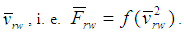 At that wagon acceleration a in the obtained differential equation of body movement is presented not in the form of derivative speed according to time dv/dt but as vdv/ds. As the result of intergrading of differential equation there has been obtained quite complicated by appearance analytical dependence of traversed path s on wagon speed v, i.e. s = f(v). Later on, analytical dependence s = f(v) due to complicity of its presentation was not used in calculation of hump geometric parameters as the unknown value here is speed v of wagon rolling down the hump gradient at any point under consideration which in its turn is dependent on wagon movement time t. Most probably, due to this impasse, in [2] the speed of wagon rolling down the hump gradient is defined on the basis of universally known in elementary physics formula of freely falling body in the form of ve = f(h) (where h is height of falling body) nonregistering the initial wagon speed v0, this becoming a classical formula being used up till now [3] though is wrong.In [4-6] there has been worked out a simplified approach to hump calculation and design. This simplified approach implies that speed v and braking path lbr in a simplified problem setting are defined on the basis of initial speed (speed of wagon entry on the braking section) v03, acceleration a under retarded motion and time of retarder braking and tbr, i. e. v = f(v03,a,tbr) f(v03,a,tbr) and lbr = f(v0,a,tbr). At that the impact of aerodynamic resistance force under wind slow speed (for instance, under fair wind 2-4 m/s) is assumed to be dependent on the square of the windward surface Aw according to the linear law, i.e.
  Wagon acceleration a in the differential equation of movement set up with the help of d’Alembert principle in coordinate form is presented as the derivative of speed according to time dv/dt. In accordance with this approach in [4] there has been solved a special case of the problem of defining wagon braking path under the impact of head wind of small value when wagon retarder is located on the hump horizontal platform. However, up till now there has not been solved the problem of defining wagon acceleration and speed as well as wagon braking path on the section of the first braking position (hereafte - 1st BP) located on the hump gradient under the impact of fair wind of small value.The present article is the continuation of series of articles [1, 4-10] on the dynamics of wagon rolling down the hump profile. Special reference should be made to the fact that many statements and analytical formulas derived in [4-7] with the help of methods put forward by us will be used in this article as well.
2. The Purpose of the Article
The purpose of the present article is the construction of mathematical model of wagon movement with braking action on the 1BP hump section located unlike [4] on the hump gradient under the impact of fair wind of small value which will make it possible to justify a rational value of hump gradient and guarantee safe wagon movement up to the design point.
3. Formulation of a Problem
In a similar manner as in [4-10] we will make use of classical fundamentals of theoretical mechanics: the basic d’Alembert principle in coordinated form [11] and general notions of differential and integral calculus [12].
4. Problem Specification and Assumed Preconditions
Unlike in [4] and taking into account the fact that in retarded state of wheel pair on the 1stBP hump section it is the wagon body with trucks that moves progressively with the wheel pair we will consider the cases when the wagon is rolling down the hump gradient linearly at given initial speed v03 (for instance, 21.5 – 22.4 km/h or 5.967 – 6.211 m/s).While rolling down the hump gradient a single wagon will experience mainly the impact of external forces in the form gravity force – of wagon with cargo or without it and aerodynamic resistance forces
  (where
  Let the wagon perform rectilinear and uniformly retarded motion at transport velocity
  down the hump respectively moving coordinates Ox1yz linked with the wagon (Figure 1) [5-7].
 | Figure 1. Vector diagram of wagon speed and fair wind on the 1st BP section |
In Figure 1 just as in [5-7] the following symbols are used: O is the beginning of moving coordinates Ox1yz, solidly linked with the wagon; Ox – is horizontal axis; ψ03 is grade angle of 1st BP hump section; H, V and W are- horizontal, vertical and front planes;  is relative wind speed in respect to moving coordinates reference system Ox1yz; λ is guide angle of wind relative speed vector in respect to longitudinal axis;
  is absolute wind speed, which is defined according to the velocity addition theorem under complex movement:
 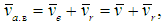 where
where  is transport velocity (wagon speed);
  is relative air velocity; ξ is guide angle of wind absolute speed vector in respect to axis Ox1 bearing in mind that it is common to assume ξ = 15° ÷ 30°, and under head wind taking into account the smallness of grade angle of 1st BP section ψ03 (ψ03 = 0,014 rad. = 0,802 degrees) it is assumed that ξ = 0.We will bear in mind that in the process of hump designing its kinematic parameters such as length projection on horizontal lh3 and grade (descend) angle ψ03 are accepted by method of selection according to recommendation to be less than 12 and not more than 15 ‰ [2, 3]. For instance, lh3 ≈ (30 – 40)m, tgψ03 = (0,012 – 0,015) (or ψ03 = 0,688 – 0,859) degrees).
5. Building of Simplified Calculation Model of Wagon Movement
A simplified model of forces impact on the system “wagon – track” on 1st BP hump section under fair wind, allowing for sliding friction of wagon wheel pair as in [7-10] is presented Figure 2. | Figure 2. Simplified model of forces impact on the system “wagon – track” on the 1st BP hump section under the action of fair wind |
All symbols in Figure 2 are the same as in [5-7]. For example, the following symbols are used in Figure 2: Mfrb and MfrbB
  are internal forces in the form of rolling friction moments in axle box bearings of front A and rear B trucks, Mfrb = MfrbA + MfrbB; PA1, PA2, PB1, PB2 being instantaneous speed centers. These rolling friction moments are later on used for defining reduced factor of rolling friction with sliding f0.In Figure 3 we present with the help of principle of releasing of constraints a calculation model of wagon movement down the 1st BP hump section.
 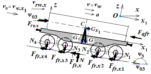 | Figure 3. Simplified calculation model of wagon movement down the 1st BP hump section under the impact of fair wind |
All symbols in Figure 3 are the same as in Figure 2 except for normal N and tangent F fr.x comprising reactions of constraints (lengths of rails). At that, N = N1 + N2 + N3 + N4 and Ffr.x = Ffr.x1 + Ffr.x2 + Ffr.x3 + Ffr.x4, as parallel forces.Here Ffr.x, unlike in [4] takes into account sliding friction of wheels against rolling surfaces of rail lengths Ffr.sl, and sliding friction of wheel flanges against lateral surfaces of rail lengths due to the impact of wind force from the lateral side of wagon Ffr.l (with regard for this impact), friction of wheel rim against compressed brake bars of the wagon retarder. Otherwise, Ffr.x = Ffr.sl + Ffr.l. + Fbr..
6. Force Correlations under Wagon Movement on the Section of the First Braking Position on Hump Gradient
Force correlations on the 1st BP section located on the hump gradient are in the following succession:1. There are defined forces of aerodynamic resistance affecting the end and lateral surfaces, in the form kN/ [5–7] 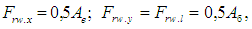 | (1) |
where 0.5 is specific pressure on 1 m2 of square, kN/m2, Ae is the square of the end surface of the wagon with cargo, m2; Ae = 2B×2H (where 2B and 2H are width and height of windward surfaces of the wagon with cargo, m), Al – is the square of the lateral surface of the wagon with cargo: (where 2L is the length of the lateral windward surfaces of the wagon with cargo, m), m2. For example, if Ae = 6,384 and Al = 27,36 m2, then Frw. x = 3,192 and Frw. y = 13,68 kN.2. In [4, 9] it has been emphasized that in an effort to provide interval-target speed regulation there is to be done braking of wheel rotation. Owing to the emerging force of sliding friction of wheel rim against compressed brake bars of wagon retarders wheels start sliding partly down rail length surfaces. During the process and due to considerable maximum pressure of compressed air in the pneumatic system (0.75MPa) braking force Fbr [13], is as well added to the force of movement resistance of wagon Ffr.x 1st BP section with braking action.3. In a general case the force of resistance of wagon movement during its passing 1st BP section with braking action is: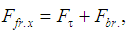 | (2) |
Fτ is tangent component of constraint reaction (rail lengths) which according to Coulon law is equal Fτ = fslN with regard for fsl – being coefficient of sliding friction of rolling wheels surfaces against the rolling surfaces of rail lengths (“metal against metal” – fsl = 0,15 ÷ 0,4 [13]); N is normal component of constraint reaction which according to module is equal to the sum of projections of all active forces upon the vertical axis falling on each box unit, N = Fz = Gz + Frw.z = Gcosψ03 + Frw.xsinψ03. Here, Frw.z = Frw.xsinψ03 is projection of fair wind force directed along the vertical (i.e. along axis Oz). That is why this force can be included into the number of forces exerting pressure on rail lengths; Fbr. = ffrbFfrw is friction force emerging between wheel pair rims and compressed brake beams of wagon retarder where ffrb = 0,14 ÷ 0,4 – is coefficient of sliding friction of wheel rim against braking bars of retarder beams, Ffrw – is pressure force of wheel rim against retarder braking bars or average load upon the wagon axis which appears during retarder actuation (normally assumed to be 90, 100, 140,150 kN depending on the retarder type and air pressure) [13].Rewriting expression (2) with regard for Fτ = fsl(Gcosψ03 + Frw.xsinψ03), we will get the expression of braking force Ffr.x, which is the cause of wagon movement with deceleration for the case of wheel pair pure sliding in respect to braking bars in the form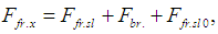 | (3) |
where Ffr.sl is sliding friction force of wheel pair rolling surfaces against rail length surfaces: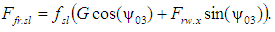 | (4) |
It should be noted that friction force fslFrw.xsinψ03 from the projection of fair wind force upon the vertical Frw.z = Frw.xsinψ03 due to its petty value can be neglected – it is as small as 0.0089 kN, as fsl = 0,2, Frw.x = 3,192 kN, sinψ03 = 0,014;Ffr.sl0 is sliding friction force of wheel flanges against rail length lateral surfaces: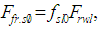 | (5) |
with regard for fsl0 being sliding friction coefficient of wheel flanges against rail length lateral surface (it is normally assumed fsl0 = 0,25) [5-7].2. Making use of the notion of “shearing” and “restraining” forces there have been calculated all the forces acting upon the rolling wagon on the 1stBP section located on the hump gradient, kN:– “shearing” forces Fsh.x (i.e. projections of gravity force of the wagon with cargo (Gx1 = Gsinψ03) and forces of aerodynamic resistance of fair wind (Frw.x1 = Frw.xcosψ03) on the direction of rolling wagon (i.e. along axis Ox1):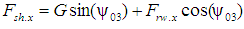 | (6) |
– “restraining” forces Fres.x (i.e. forces of resistance to wagon movement in the form of the impact of fair wind force upon the wagon end surface, Frw.x, sliding friction force Ffr.sl of wheel pairs with regard for the impact of the wind from the wagon lateral side Ffr.l, retarder braking force Fbr and the force of resistance to any movement Fr.)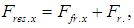 | (7) |
where Ffr.x is sliding friction force (according to [2, 3] is the major resistance);Fafr. are forces of resistance of any kind in the form: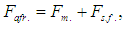 | (8) |
with regard for Fm., Fs.f. being the forces of resistance to wagon movement from the medium, snow and frost (according to [2,3] they present additional resistance):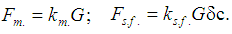 | (9) |
Here km is coefficient taking into account a share of gravity force G with regard for medium resistance (normally within the limits of 0.0005 ÷ 0.00011 at fair wind speed from 4 m/s to 6 m/s) [2, p.182]; ks.f. is coefficient demonstrating a share of gravity force G accounting for resistance to movement from snow and frost [2, 3]; δc is Dirac unit function taking into account climatic conditions of hump operation, (winter and/or summer periods), for example δc = 1 takes into account winter period, δc = 0 takes into account summer period. Here letter c denotes the first letter of the expression “climatic conditions of hump operation.” Substituting (3) and (8) into (7), force Fres.x can be presented in the form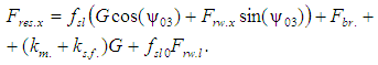 | (10) |
Summarizing the results of previous considerations and taking into account (5) and (9) it is possible to find the condition of wagon movement with deceleration on the 1st BP section located on the hump sections with gradients 12 < i < 15 ‰ or 0,688 ÷ 0,859 degrees (Fig. 1) under the impact of fair wind [9]: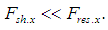 | (11) |
Under compliance of condition (11) there may occur complete stop of wagon on hump braking positions which may be the case in reality.Let us find the expression of forces causing abrupt deceleration of the wagon on the 1st BP hump section in the form [4]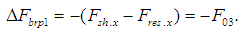 | (12) |
The analysis (12) shows that force  which emerges on the 1st BP hump section is a retaining (“braking”) force providing wagon abrupt deceleration of prescribed gravity force G under the impact of fair wind right up to a complete stop.
7. The Construction Method of Mathematical Model of Wagon Movement on the 1st Hump Braking Position
In a similar manner as in [4-10] we will write the fundamental law of dynamics for transient motion of the wagon with nonideal constraints (or d’Alembert principle) in coordinate form [11]: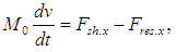 | (13) |
where M0 is mass of wagon with cargo without considering the mass of rotating parts (wheel pairs), kg; Fsh.x and Fres.x are “shearing” and “retaining” forces for the case of wagon braking by a braking device, N.
8. Mathematical Models of Crash Stop by a Braking Device
We rewrite equation (13) taking into account expressions (6) and (10) in the moment of starting braking retarder in the form of differential equation of wagon movement on the 1st BP hump section: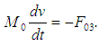 | (14) |
where F03 = Fsh.x – Fres.x is the force of resistance to wagon movement as Fsh.x < Fres.x < 0, Н.Initial conditions of Cauchy problem under t = 0: v(0) = v0 (where v0 – is wagon entry speed on the 1st BP hump section.Separating variables in (14) we will get (11):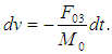 Having integrated both parts of the equation we will have [12]:
 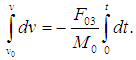 After integrating we will get well known elementary physics formula of body speed under retarded motion
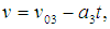 | (15) |
where a3 is acceleration under which rectilinear uniformly retarded motion of a wagon takes place, m/s2: | (16) |
Evidently, wagon speed ve(t) in the course of time t is dependent on speed v03 and wagon acceleration a3, i.e. ve(t) = f(v03, a3, t).Analyzing (16) it should be noted that the wagon on the 1st. BP section located below hump gradient performs rectilinear uniformly retarded motion. At that, acceleration a3 on this particular hump section is dependent on all forces affecting the system “wagon – track” (Fsh.x = f(G), Fres.x = f(Frw.x, Ffr., Fr., Frw.l) and on mass of the wagon (wagon cut) with cargo (or without it) M0 nonregistering wheel pair mass, i.e. a3 = f(M0, Fsl.x, Fres.x).It has been observed that braking time tbr unknown. So tbr should be selected so as to fulfill the condition tbr > tres, where tres – the response time of a wagon retarder (usually 0.7 or 0.8 seconds, depending on the design of inhibitors [13]). That is why using (16) it is possible to define wagon speed v(tbr). on the hump first braking position at the end of braking.Further on, taking into account that  we rewrite (15) in the form of differential equation of wagon movement during its retarded motion
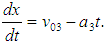 Initial conditions of Cauchy problem at t = 0: x(0) = 0.Multiplying both parts of the above equation by dt and integrating the obtained equation within the limits from 0 to t, and leaving out intermediary calculations we will finally get braking path (skidding) of the wagon in the course of time t on the 1st BP hump section, m
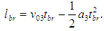
 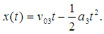 | (17) |
As is seen, wagon braking path (t) in the course of time t is described according to the square law (17): at retarder actuation wagon braking path increases non-linearly,Analyzing (17) we got convinced that x(t) in the course of time t is dependent on the initial speed v03 and wagon acceleration a3, i.e. x(t) = f(v03, a3, t). From expression (17) at t = 0, we will have x = 0, i.e. the initial condition is observed.It should be noted that wagon braking time tbr unknown and it should be taken so as to keep the condition tbr > tres. That is why it is possible to define directly from expressions (15) and (17) speed v(tbr) and the path traversed by the wagon x(tbr) = lbr at the end of braking time tbr, s.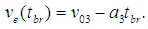 | (18) |
 | (19) |
It is significant that (18) and (19) are well known elementary physics formulas of speed and the distance under retarded motion of the body.Thus, with the help of d’Alembert principle, method of variable separation and integral table, just as in [4-7]. There have been derived final analytical formulas for defining acceleration of wagon a, its speed on the 1st BP hump section ve(t) in the course of time. It has been observed that on the basis of known value of wagon braking time tbr it is possible to define speed at the end of braking v(tbr) and distance, (path) traversed by the wagon tbr) = lbr.
9. Conclusions
1. Mathematical models of wagon movement under abrupt braking of the wagon on the 1st BP section located on the hump gradient with an allowance for the impact of gravity force and fair wind which have been obtained on the basis of classical statements of theoretical mechanics made it possible to define analytical formulas of acceleration abr and wagon speed ve(t), and also braking path ve(t), according to braking time of wagon retarder of a specific design.2. The derived analytical formula of wagon acceleration abr at the braking time when deceleration tbr a specific method of selection it possible to define a specific value of the speed at the end of braking v(tbr) and wagon traversed path during its braking x(tbr) = lbr. 3. In hump designing rational value of platform gradient for installing wagon retarders can be defined by variation of the gradient value within limits from 0 to 15 ‰ (from 0 to 0.015 rad.). At that ψ03 = 0 corresponds to the retarder location on the horizontal platform.The results of the investigations can be used for calculation and designing of hump intermediary section.
References
| [1] | Turanov Kh.T. and Gordienko A.A. Some problems of theoretical precondition of dynamics of wagon rolling down hump gradient. Transport information bulletin, 2015, # 3 (237). pp. 29−36. [In Russian: Некоторые проблемы теоретической предпосылки динамики скатывания вагона по уклону сортировочной горки. Бюллетень транспортной информации, 2015]. |
| [2] | Obraztsov V.N. Railway stations and junctions. Part II. M.: Transhzeldorizdat, 1938. 492 p. [In Russian: Станции и узлы. ч. II. М.: Трансжелдоиздат». 1938]. |
| [3] | Railway stations and junctions: manual / V.I. Apattsev et. al; edited by V.I. Apattsev and Yu.I. Efimenko. M.: “Training and methodical center of education on railway transport”. 2014. 855 p. [In Russian: Железнодорожные станции и узлы: учебник. ФГБОУ «Учебно-методический центр по образованию на железнодорожном транспорте». 2014]. |
| [4] | Turanov Kh.T. and Gordienko A.A. Investigation of wagon movement with deceleration on the 1st BP hump section under the impact of head wind. Transport: science, engineering, operation. 2015, # 5. pp. 3 − 6. [In Russian: Исследование движения вагона с замедлением на участке первой горочной тормозной позиции сортировочной горки при воздействии встречного ветра. Транспорт: Наука, техника и управление, 2015]. |
| [5] | Turanov Kh.T. and Gordienko A.A. Mathematical model of wagon rolling time down the first high speed hump section under the impact of fair wind of small value. Transport information bulletin. 2015, # 6 (240). pp. 17 − 23. [In Russian: Математическая модель времени скатывания вагона на первом скоростном участке сортировочной горки при воздействии попутного ветра малой величины. Бюллетень транспортной информации, 2015]. |
| [6] | Turanov Kh.T. and Gordienko A.A. Analytical determination of wagon rolling time down the second high speed hump section under the impact of fair wind of small value. Transport science and engineering. 2015, # 2. pp. 73 – 81. [In Russian: Аналитическое определение времени скатывания вагона на втором скоростном участке сортировочной горки при воздействии попутного ветра малой величины. Наука и техника транспорта, 2015]. |
| [7] | Khabibulla Turanov, Andrey Gordiienko and Alena Myagkova. (2015). Analytical Description of Wagon Motion on the Second Speed Section of the Marshalling Hump with Switch Zone under the Impact of Fair Wind. Journal of Multidisciplinary Engineering Scince and Technology (JMEST), Vol. 2 Issue 11, November – 2015. ID: JMESTN42351205. Berlin, Germany. JSSN: 3159-0040 (Online). |
| [8] | Khabibulla Turanov. The dynamics of the wagon rolling down the hump profile under the impact of fair wind / Khabibulla Turanov // Direct Research Journals of Engineering and Information Technology (DRJEIT). Vol. 2(2). pp. 17-24. May 2014. JSSN 2354-4155 (http://directresearchpublisher. org/drjet /archive/ 2014/May/pdf/Turanov.pdf). |
| [9] | Turanov, K. and Gordiienko, A. (2015). Analitical Determination of Conditions of Wagon Rolling Doun Marshslling Hump Profiles. Open Acces Library Journal, 2, e1912. doi: http: //dx.doi.org /10.4236 / oalib.1101912. PP.1-11. |
| [10] | Turanov Kh.T. and Gordienko A.A. Refined mathematical models of wagon rolling speed down the gradient hump under the impact of gravity force and fair wind. Transport: science, engineering, operation. 2015, # 1. pp. 15 − 21 [In Russian: Уточнённые математические модели скорости скатывания вагона по уклону горки при воздействии силы тяжести и попутного ветра. Транспорт: Наука, техника и управление, 2015]. |
| [11] | Loitsyansky L.G. and Lurje A.I. The course of theoretical mechanics. Vol.II. Dynamics. M.: Science, 1983. 640 p. [In Russian: Курс теоретической механики. Т.2. Динамика. М: Наука. 1983]. |
| [12] | Bronstein I.N. and Semendyaev K.A. Mathematics handbook for engineers and technical college students. M.: Science, 1980. 976 p. [In Russian: Справочник по математике для инженеров и учащихся втузов. М.: Наука, 1980]. |
| [13] | Kobzev, V.A. Technical means of hump safety. Part 1. The tutorial, M: MIIT. 2009. pp: 92 [In Russian: Технические средства сортировочных горок, обеспечивающие безопасность движения. Часть 1. Учебное пособие. – М.: МИИТ, 2009]. |

 Abstract
 Reference
 Full-Text PDF
 Full-text HTML