
-
Paper Information
- Previous Paper
- Paper Submission
-
Journal Information
- About This Journal
- Editorial Board
- Current Issue
- Archive
- Author Guidelines
- Contact Us
Science and Technology
p-ISSN: 2163-2669 e-ISSN: 2163-2677
2015; 5(1): 5-14
doi:10.5923/j.scit.20150501.02
Mathematical Modeling of Cargo Motion Crosswise the Wagon under the Action of Plane Force System
 Abstract
 Reference
 Full-Text PDF
 Full-text HTML
Khabibulla Turanov
Urals State University of Railway Transport (USURT), Russia Federation, Yekaterinburg, Russia
Correspondence to: Khabibulla Turanov, Urals State University of Railway Transport (USURT), Russia Federation, Yekaterinburg, Russia.
| Email: |  |
Copyright © 2015 Scientific & Academic Publishing. All Rights Reserved.
For the first time in the theory of solid cargo fastening there has been investigated a case when the cargo is in motion in relation to the wagon floor with acceleration, its speed being at this moment equal to speed. There have been set out the results of mathematical description of cargo motion in relation to the wagon. It has been established that the lateral force perceived by the flexible fastening elements in value is smaller than the force obtained when inertia force in relative motion (at rest) is not taken into account. Hence, the cargos displacement crosswise the wagon in this case will be smaller. This, in its turn, will affect the decrease of elongation value and consequently the decrease of the effort of every flexible element, thus increasing their load-carrying capacity.
Keywords: Cargo, Open rolling stock, Thrust bars, Flexible fastening elements, Cargo motion relative to the wagon, Effort in flexible fastening elements
Cite this paper: Khabibulla Turanov, Mathematical Modeling of Cargo Motion Crosswise the Wagon under the Action of Plane Force System, Science and Technology, Vol. 5 No. 1, 2015, pp. 5-14. doi: 10.5923/j.scit.20150501.02.
Article Outline
1. Introduction
- As it has been noted in [1-17], the end formulas for defining efforts in cargo flexible fastening elements under the action of lateral and vertical forces, presented in Appendix 8 [18] are the results of incompletely solved problems where the value of lateral force perceived by fastening means according to gravity force of cargo G is understated (i. e. always vary within (0,3 ÷ 0,34)G, whereas during train movement on a curved section this force can have value – (0,4 ÷ 0,55)G [15]. Moreover, they don’t take into account the efforts of preliminary twisting of every fastening wire R0 [4, 5], without which the cargo is not liable to dispatching. Just because due to effort R0 the cargo is pressed against the wagon floor, friction force is increased. In [18] there is no mention of the notion of «displacement of the cargo crosswise the wagon” and hence, no mention of “elongation of each fastening element” to the value of which the efforts in each fastening elements are according to Hooke’s law directly proportional. As a result, the efforts of each fastening element have one and the same value, which disagrees with reality. It should be noted that in [1-16] a technical problem of cargo fastening under the action of space force system and, as a special case, under the action of plane force system, is solved within the fundamental law of dynamics during relative motion at rest. In addition, in [19] for the first time there has been considered the case when the cargo is moving lengthwise the wagon floor with acceleration
 its speed at the moment being equal to
  (i. e. in dynamics). The possibility of this approach which can be demonstrated by the example of the movement of deformed flexible thread on an uneven curvilinear surface is well-known [20]. Unfortunately, there has not been yet considered the case when the cargo is moving crosswise the wagon floor with acceleration
  its speed at the moment being equal to
  .On this basis it can be noted that determining of cargos displacement crosswise the wagon floor and correspondingly elongation and efforts in each fastening element during cargo motion with acceleration in relation to the wagon floor at a given relative speed is an urgent technical problem for transport research. The aim of our investigation is to fill in this gap.
2. Problem Formulation in Dynamics
- To derive an analytical formula of cargos displacement crosswise the wagon, elongation and efforts in flexible fastening elements in case of the cargo moving in relation to the wagon floor with acceleration
 at speed
  (i.e. in dynamics) [19, 20].
2.1. Problem Specification
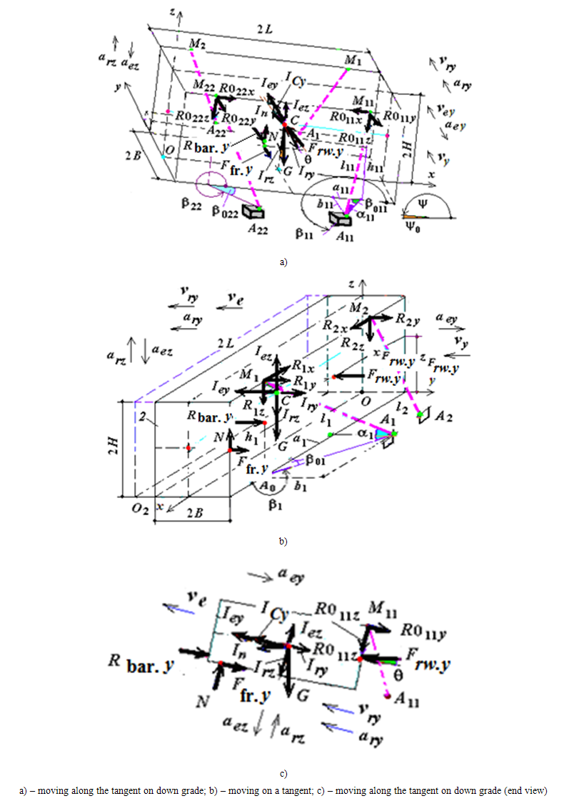
- As in [2, 4, 5, 7], let us consider the case, when cargo with gravity force
 , located on the open rolling stock (further on in the wagon) which is kept from cargos displacement by flexible fastening elements (for example, in the form
  and
and  ) and a wooden thrust bar (fig. 1).
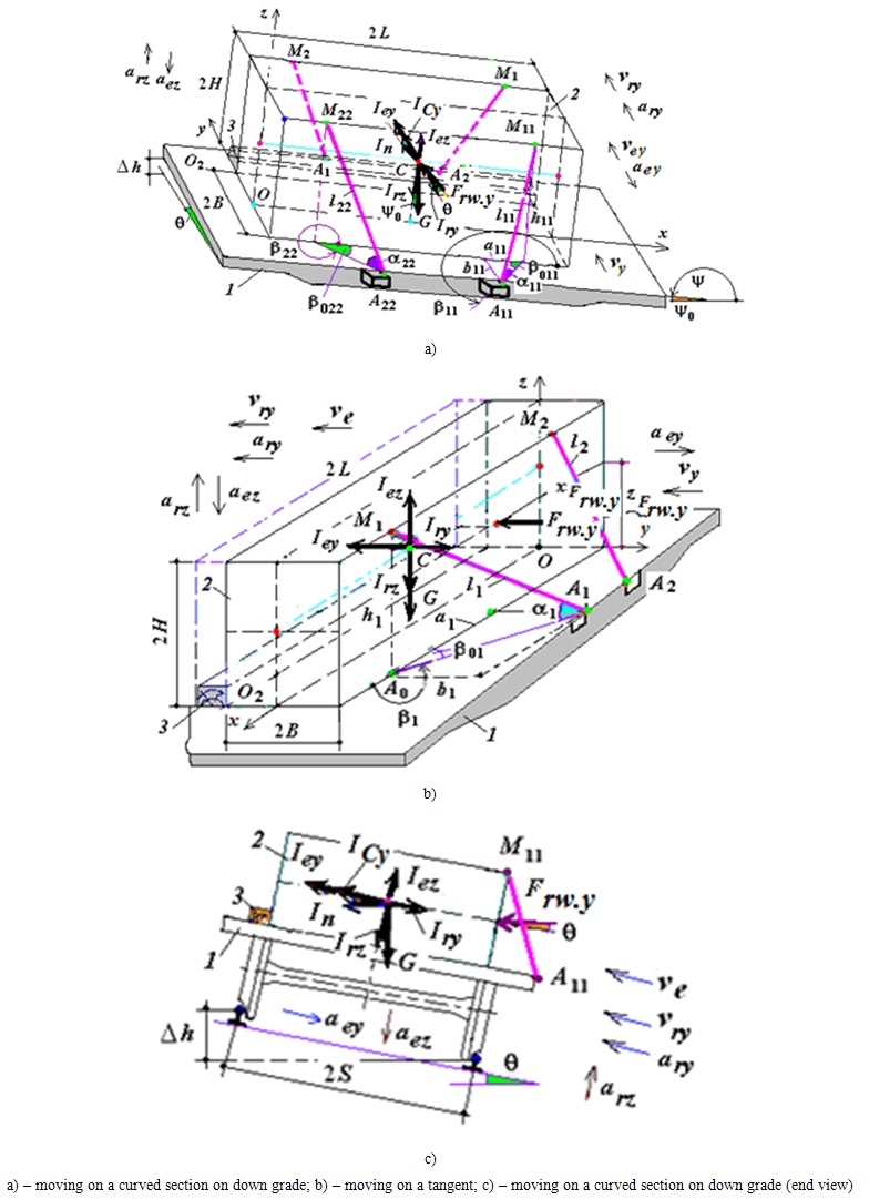 | Figure 1. Diagram of allocating cargo and thrust bar on the wagon: 1 – wagon, 2 – cargo, 3 – thrust bar |
 ,
,  and
and  ,
,  are flexible fastening elements of both directions; M1, M2, M11, M22 are shipping loops (eyelets); α и β are angles characterizing the geometry of flexible fastening elements [4, 5, 7]. It also has symbols:
 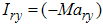 and
and 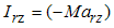 – inertia forces in relative motion on lateral and vertical axes;
  and
and  are lateral and vertical transferring inertia forces (the physics of emergence of these forces is described in [4, 6, 7];
  and
and  are normal component of inertia (D’Alamber) force
  and Carioles inertia force (the physics of emergence of these forces is described in [4, 7, 21, 22]);
  aerodynamic resistance force(the physics of emergence of these forces is described in [7, 21, 22]).
2.2. Man-Made Assumption
- In working out a computable model as in [21] we assume wagon frame to be the major constrain for the cargo (object) and flexible elastic fastening elements and thrust bar to be additional constraints [4-7] (figure 1).We assume that effective lateral and vertical forces are perceived by flexible elastic fastening elements located along the direction of the action of sheer forces while fastening elements of opposite direction which are not shown in figure 1a sag.An additional constraint (a thrust bar) is a single-sided one, it prevents the cargo from shifting from the contact plane to one side (to the left) and not keeping it from shifting to the other side (to the right).We assume that flexible fastening elements are pre-tensioned by efforts R0i (for example, R01 = R011 = R02 = R022 = 20 kN) [4, 5, 7] and they increase normal component
 of constraint reaction (platform floor), therefore, cargo and floor cohesion force
  . (and hence sliding friction
  meaning that
  ).As in [1-7], we resolve external constraint reaction (non-ideal)
  into normal
  and tangent
  component, i. e.
  . Coordinates
  (or ), points of application of external constraints reaction
  are not known and are to be defined.
2.3. Formation of Dynamic Model
- We apply theoretically to the mass center of material system (cargo) C just as in Fig. 1 the active force – gravity force
 , inertia force at relative motion along the lateral axis
 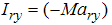 and vertical axis
 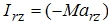 , lateral and vertical transferring inertia forces
  and
and  , aerodynamic resistance force
  , thrust bar reaction
  and also wagon floor reaction (
 ) and efforts of preliminary twisting of fastening wire
  . We will take into account the fact that these forces exert influence on the external constraints (platform and fastening means). We apply to the object (cargo), active forces (reactive forces) (
 ,
, ,
, ,
, ,
, – we will take into account the fact that these forces exert influence on the external constraints (platform and thrust fastening means). Reactive forces
  ,
, and
and  are directed to the object while, forces
  – from the object. Motions of the train with cargo with acceleration
  will be taken into account by normal component of
  inertia (D’Alamber) force
  . We will direct force
  from the object parallel to the horizon and symbolically apply it to the mass center of material system (cargo) C. Then we show coordinate axes Oy and Oz. As a result we will get a dynamic model of the cargo (figure 2).The action of lateral and vertical transferring inertia forces
  and
and  , Carioles inertia force
  , aerodynamic resistance force
  ,
,  will be experienced only by the thrust bar as it is closely nailed to the cargo lateral surface located oppositely to the action of these external forces. Force
 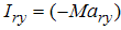 as retaining force will be instrumental in keeping cargo from shifting. Hence, it is arguable that as long as the cargo is kept from lateral shift by thrust bars flexible elastic fastening elements will not perceive any external forces. Flexible fastening elements may experience the action of external forces only when there takes place a shift of thrust bars with a bend of fastening items (nail) [5].
3. Methods of Solution
- The formation of dynamic and constructing a mathematical model of cargo movement on a wagon is based on classical concepts and provisions of theoretical mechanics (for example, constraint and their reactions, the principle of ties release of the fundamental law of dynamics of the relative motions of records) [4, 7, 19, 22, 23]).
3.1. Problem Analytical Solution
- Unlike in [10, 13, 22, 23], for deriving an engineering formula we will use the fundamental law of relative transferring cargo motion during rolling stock movement along tangent described by the equation in vector form
 | (1) |
 | Figure 2. Dynamic model of cargo motion on the wagon |
 is cargo relative acceleration ( or acceleration of cargo relative to the wagon floor), corresponding to cargo speed
  [19, 20, 23].As applied to the problem in question
 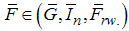 is active force,
  being normal component of inertia (D’Alamber) force
  taking into account only the motion of rolling stock on a curved track section with acceleration [12-15];
  is aerodynamic resistance force,
  is reactive force (elastic forces of flexible fastening elements
  thrust bars reaction
  , friction force
  ;
; 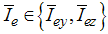 – lateral and vertical transferring inertia forces,
  , Carioles inertia force
  .It should be noted that equation (1) is a differential equation of relative motion of a material point [22, 23]. But for deriving engineering formulas it can be looked upon as an equation of equilibrium of dynamics forces applied to the body [19, 20].
4. Results of Solution
4.1. Mathematical Solution of the Problem
- Just as in [19] assuming that the cargo is moving against wagon floor with acceleration
 , its speed being
  we will write dynamic equation of forces [2] in projections on coordinate axes Oy and Oz in the form
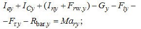 | (2) |
 | (3) |
 and
and  are projections of inertia force in relative motion on coordinate axes Oy and Oz; are projection of gravity force on coordinate axes Oy and Oz;
  ,
, ,
, and;
and; 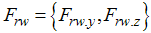 are active forces, Iny being projections of normal component of inertia (D’Alamber) force on axis Oy; and are reactive forces. At that
  are elastic forces (tension) of additional constraint (cargo flexible fastening element),
  and
and  are normal and tangent components of wagon reaction (constraint)
  ;
;  is reaction of fastening thrust element. Symbol i in the power of elastic force
  designates that the force is dependent on the number of fastening flexible elements but it doesn’t mean that it is to be summed according to i. Elastic force
  has only one meaning [4, 7, 19]. It should be emphasized that equations (2) and (3) are dynamic equations of forces acting on the system “wagon – cargo – fastening” emerging during the motion of a wagon with cargo on a curved track section.As applied to the cargo located on the wagon Carioles inertia force
  emerges during train passage from tangent onto a curved track section and while the train is moving on a curve (including the passage onto the side line), which is the cause of cargo shift both lengthwise (while passing a joint) and transverse the wagon. In so doing Carioles inertia force directed transverse the wagon is caused by cargo shifting lengthwise the wagon and is directed according to normal from the center of curvature, i.e. it facilitates cargos displacement crosswise the wagon [4, 7].Presenting elastic forces i-flexible fastening elements with allowance made for tensions of preliminary wire twisting of fastening
  on axis Oy we will rewrite (2) and (3) in the form
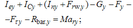 | (4) |
 | (5) |
 are projections according to normal component of inertia (D’Alamber) force and aerodynamic resistance force and also cargo weight and elastic forces i-flexible fastening elements with allowance made for tensions of preliminary wire twisting of fastening
  on axis Oy derived from expressions
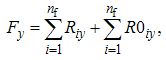 | (6) |
 is the number of fastenings of one direction (items);
  as yet unknown tangent component of constraint reaction
  ;
; are projections of cargo gravity force, inertia (D’Alamber) force normal, elastic forces i-flexible fastening elements with allowance made for tensions of preliminary wire twisting of fastening
  on axis Oy derived from expressions
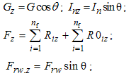 | (7) |
 is as yet unknown normal component of constraint reaction (wagon floor)
  .From expression (5) we have
 | (8) |
 | (9) |
 or in terms of formula (7) we have
 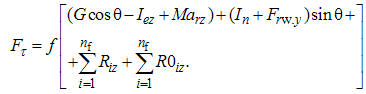 | (10) |
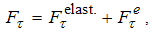 | (11) |
 and
and  are friction forces of elastic and external forces
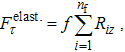 | (11a) |
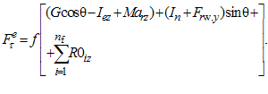 | (11b) |

 Let us rewrite the latter expression in terms of (11 a) and (11 b)
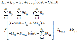 After elementary transformations of the latter expressions we determine projections of unknown elastic forces (tension) i-flexible fastening elements onto lateral axle Oy
 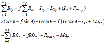 We rewrite the derived expression in the form
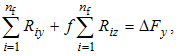 | (12) |
 are lateral forces perceived by cargo flexible elastic fastening elements
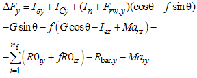 | (13) |
 is design value of reactions of fastening elements (thrust bars) calculated according either to arbitrarily chosen or, just as in [10], scientifically grounded number of fastening elements (nail) based on cargo profile. In this way, for example, are defined reactions of thrust bars ((12) [11, 15]):[Rnail] = 1,08 is permissible value of force per a fastening item (nail), kN (table 32 Appendix 14 to International Rail Freight Transportation Agreement [18]);nbar.y is accepted number of thrust bars according to the cargo allocation and fastening scheme, item ( Fig. 1);k1 is strength coefficient of thrust bars fastening taking into account wagon floor state, item ( normally accepted to be 0,5 ÷ 0,6);nnail.y is accepted value of required number of nails per a thrust bar, item;Rbar.y = k1·nnail.y·nbar.y·[Rnail] is permissible load per one fastening item (nail) ((46) Appendix 14 to International Rail Freight Transportation Agreement [18]). For example, for a nail with ∅4 and length 100 ÷ 120 mm [Rnail.] = 0,047 кН, for a nail of ∅6 and length 150 ÷ 200 mm [Rnail.] = 1,08 кN. According to the standards of European countries for a fastening item of ∅5 mm and length100 ÷ 150 mm [Rnail.] = 1,25 кN, and for an item of ∅6 mm and length 150 ÷ 200 mm [Rnail.] = 1,5 кN [19, 24, 25].By introducing notions of “shearing” and “retentive” forces [3-5] we rewrite the above expression (13) in the form
 | (14) |
 | (15) |
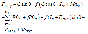 | (16) |
 ) and thrust bar (Fig. 1). Then according to the method of determining deformations at minor displacement we project a new point position first onto “original” or “old” direction of thrust element [5, 6, 22]. As a thrust element is arbitrarily located in space for calculating the projection it is necessary to make use of the method of double projection the way it is done in theoretical mechanics for arbitrarily located force [3, 4, 18]. Based on this we’ll write a formula for finding elongation of fastening flexible elements depending on cargo shift along the wagon
  and fastening geometrical parameters
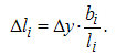 | (17) |
 is the length for each flexible elastic fastening element, m,
 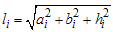 taking into account the fact that
  ,
,  and
and  are projections of each flexible fastening element onto longitudinal Ox, crosswise Oy, and vertical axis Oz.It is obvious that elongation in the flexible elastic fastening element will occur only when there is cargos displacement transverse the wagon at value
  .According to [4, 5] the movement of cargos displacement transverse the wagon as one-mass oscillatory system can be presented in the following way (figure 3)
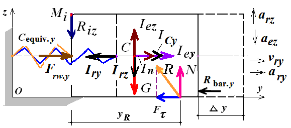 | Figure 3. Cargo movement crosswise the wagon as one-mass oscillatory system |
 onto the lateral axis which were according to Hooke’s law the results of cargo displacement crosswise the wagon
  is replaced by a spring with equivalent rigidity
  stretched out at the value of the shift. In its turn, spring with equivalent rigidity
  (figure 4) stretched out at the value of cargos displacement crosswise
  is replaced by flexible efforts
  .
. | Figure 4. Dynamic model of cargo loaded by lateral and vertical forces |
 being equivalent (either reduced or generalized) rigidity of flexible fastening elements along lateral axis Oy.In expressions (12), (13) and (16) projections of elastic forces (effort and tension) of i-flexible elastic fastening elements onto lateral and vertical axes Oy and Oz are determined according to the formulas [2 – 5, 7]
 or taking into account (12),
 | (18) |
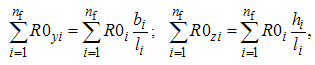 | (19) |
 is a number of flexible elastic fastening elements; ci − is rigidity of i-flexible fastening element from annealed wire (kN/m):
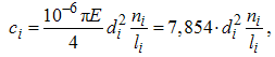 | (20) |
 is cargos displacement crosswise the wagon;
  is tension of preliminary twisting of i-flexible fastening element.Substituting (12) for (18) we get
 or
or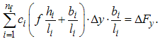 Putting equality (20) into the above expression we will get
 Hence, just as in [2-5] we can finally find cargos displacement t crosswise the wagon
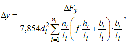 | (21) |
 is lateral force determined by formula (14) − (16) with consideration for second expression (19):
 | (15a) |
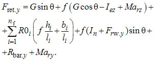 | (16a) |
 acts from the cargo rear back, this force should be put in the formula with a negative sign with consideration for coordinates of its application.From (21) it can be observed on the basis (14) that first, cargo shift crosswise the wagon will occur (i. e.
  ) only when
  and second, breakup of flexible fastening elements will not take place only on condition that
  where
where  is an allowable value of cargo displacement crosswise the wagon (mm) determined according to value
  (Table 30 Appendix 14 to International Rail Freight Transportation Agreement [18]).While solving practical problems with the help of formula (21), just as in [4, 5, 7, 11, 13, 11, 16] we will assume that maximum normative values of lateral transferring accelerations
  is equal to
  on a track tangent,
  − on a curved section, and vertical transferring accelerations
  resulting from deviations in track maintenance standards are equal to −
  . In accordance with this statement it is possible to accept
  on a tangent,
  on a curved section and
  (see also [24, 25]).In a special case when a wagon with cargo is moving on a tangent from formulas (15) and 16) there will be excluded Carioles inertia force and force
  (since ρ = 0) and also super elevation angle
  (i.e.
(i.e.  ). In these cases formulas (15) and (16) will have a simple form of:
 | (15b) |
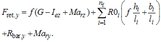 | (16b) |
 with consideration for physical-geometrical characteristics of flexible elements (i. e.
  ), values of external forces (
 ), perceived by fastening elements and cargo, and the state of cargo contact surfaces and wagon floor taken into account by friction coefficient (f). It should be noted that normal component of
  inertia (D’Alamber) force
  and Carioles inertia force ICy in practical calculations can be neglected because of their insignificant value (less than 10% of cargo gravity force (for example, 700 kN) at train’s speed 100 km /h) [7, 11, 13, 16].Using the derived value of cargo displacement crosswise the wagon
  , in compliance with Hooke’s law we determine effort (tension)
  in i-flexible fastening element, kN [4, 7, 10, 12, 15]:
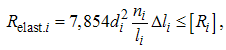 | (22) |
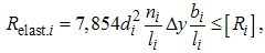 | (22a) |
 is allowable value of effort in fastenings, determined according to the Table 30 Appendix 14 to International Rail Freight Transportation Agreement depending on a number of threads ni and wire diameter di. [18].Effort (tension)
  in a flexible fastening element is according to axiom: to every action there is an equal reaction is equal to the reaction in this element.It should be emphasized that the obtained results of mathematical modeling of cargo fastening on the wagon ((17) and (22)) make it possible to perform an engineering calculation of solid-state cargo fastening on the wagon.
5. Conclusions
- 1. Summarizing the results of the research carried out it can be noted that a technical problem of cargo fastening on the wagon with flexible and thrust elements under the action of plane force system has been correctly solved on the basis of equilibrium equation at relative motion.2. For the first time in the theory of fastening of solid-state goods there has been derived a formula for determining “retentive” force with allowance made for reactions of thrust fastening elements and inertia forces in relative motion on condition that the cargo moves in relation to the wagon floor with acceleration
 its speed at the moment being
  .3. When considering cargo motion in relation to the wagon floor with acceleration
  at speed
  it should be noted that lateral force perceived by flexible fastening is smaller in value than the force the value of which was obtained without taking into account the inertia force in relative motion (at rest). Therefore, cargo shift crosswise the wagon in this case will also be smaller. This, in its turn, will affect the decrease of elongation value and hence the decrease of the effort of each fastening element meanwhile increasing their loading capacity.The distinctive feature (its novelty) of the constructed mathematical model under the action of plane force system as compared to the previously known ones in rolling stock motion on a curved track section [5 – 12] lies in taking into account the inertia force in relative motion along both the lateral and vertical axes.