-
Paper Information
- Paper Submission
-
Journal Information
- About This Journal
- Editorial Board
- Current Issue
- Archive
- Author Guidelines
- Contact Us
Science and Technology
p-ISSN: 2163-2669 e-ISSN: 2163-2677
2014; 4(2): 22-29
doi:10.5923/j.scit.20140402.03
Design and Calibration of a Tilting Tunnel Respirometer to Study Non-horizontal Swimming in Fishes
 Abstract
 Reference
 Full-Text PDF
 Full-text HTML
Rachel Venn Beecham1, C. Douglas Minchew2, S. D. F. To3, Glenn R. Parsons4
1Department of Biology, Box 1848, Mississippi Valley State University, MS 38677-1848, Itta Bena
2Mississippi State University, Delta Research and Extension, PO Box 197, Stoneville, MS 38776
3Mississippi State University, Dept. of Ag and Bio Engineering, Box 9632, Mississippi State, MS 39762
4University of Mississippi, Department of Biology, Box 1848, University, MS 38677-1848
Correspondence to: Rachel Venn Beecham, Department of Biology, Box 1848, Mississippi Valley State University, MS 38677-1848, Itta Bena.
| Email: |  |
Copyright © 2014 Scientific & Academic Publishing. All Rights Reserved.
A swimming tunnel respirometer was designed, contructed, and used to study non-horizontal energetics and locomotion of fishes. The tunnel was similar in design to that described by Blazka (1960) with several enhancements: (1) the respirometer was lengthened and had a 60 inch length with a 45 inch working section, and with 39 effective inches of swimming space; (2) the design included an innovative seal and shaft support system; (3) a redesigned and streamlined swim tube mounting system; (4) an easily read inclinometer for setting angles; (5) an rpm gauge on the motor shaft to simplify the setting of water flow rate; (6) an A-frame and tilting rack assembly to enable safe and stable support and operation; and (7) the incorporation of a winch system to facilitate automation of the mechanical process. This tunnel allows researchers to study swimming at prescribed speeds at angles from 0-60 on both incline and decline orientations.
Keywords: Design, Fish, Respirometer, Swim tunnel
Cite this paper: Rachel Venn Beecham, C. Douglas Minchew, S. D. F. To, Glenn R. Parsons, Design and Calibration of a Tilting Tunnel Respirometer to Study Non-horizontal Swimming in Fishes, Science and Technology, Vol. 4 No. 2, 2014, pp. 22-29. doi: 10.5923/j.scit.20140402.03.
Article Outline
1. Introduction
- Earlier swimming tunnel respirometers (STR) were described by Blazka et al (1960) and Brett (1964). Since that time, researchers have used STR to study swimming performance, energetics, and efficiency in fish (Tucker 1970; Smit et al. 1971; Brett 1972; Beamish 1978; Brett and Groves 1979; Priede 1985; Parsons and Sylvester 1992; Webb 1995; Adams and Parsons 1998). The development of these systems allowed for advancement in knowledge of the metabolic costs of swimming in many fishes. Historically, swimming studies to determine swimming performance, swimming efficiency, and optimal swimming speed have been conducted in horizontal swimming chambers that force fish to swim horizontally against a water flow. However, fish often swim in a manner other than horizontal during their daily activities. Priede and Holliday (1980) designed a tilting Brett-type tunnel respirometer (Brett 1964) for use in their study of the metabolism of plaice (Pleuronectes platessa) in order to prevent the fish under study from adhering to the bottom of the tunnel during slow swimming. Fish may swim non-horizontally for several reasons including the following: (1) prey capture or predator avoidance; (2) vertical migration; (3) climbing fish ladders or using fishways; (4) climbing waterfalls; and (5) burst and glide swimming during migrations (Blake 1983).The purpose of this paper is to describe the design and construction of a tilting swim tunnel respirometer, based on the concepts of Blazka et al. (1960) and Priede and Holliday (1980), suitable for use in studies of horizontal and non-horizontal swimming abilities and energetics in fishes (Figure 1).
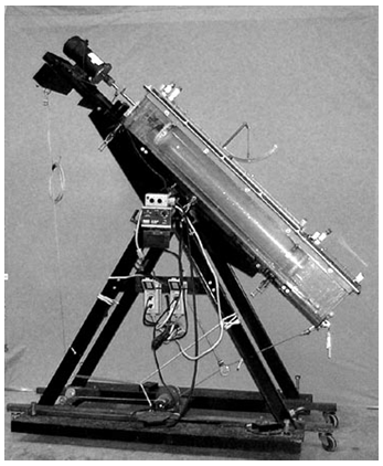 | Figure 1. Photograph of tilting tunnel respirometer |
2. Tilting Swim Tunnel Respirometer Design
2.1. Frame Construction
- Tunnel support was constructed from two A-frames (Figure 2) using 3 in channel iron. A portion of the top apex of each A-frame was cut off to form a trapezoid with a channel iron welded across them. A bracing member of 6.0 in long was welded near the top portion of each A-frame for structural stability. The A-frames were erected in parallel and secured with channel iron bracings at the top and the base, and the structure was bolted to a wheeled flat-bed platform. A tilting rack, which served to hold the swimming apparatus, was mounted to the top brace of the structure. The tilting mechanism was actuated using a steel cable anchored at both ends using I-bolts thru a system of pulleys and an electric winch (Superwinch Model W115, Superwinch Inc., Putnam, CT). The pulleys and winch were positioned at the base of the structure. The pulleys and the electric winch spooling mechanism were aligned with the center line of the structure. The pulleys were located at each end of the base and the winch was positioned at the center between them. A mounting plate for a motor control unit and a digital RPM readout was welded to one side of the A-frame near the top, and a wooden board was fastened midway on the same side of the A-frame as a mounting structure for two commercial grade ground fault circuit breakers.
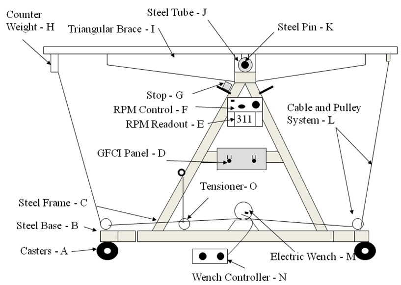 | Figure 2. A-frame and Tilting Rack |
2.2. Tilting Rack Construction
- The tilting rack (Figure 2) was a rectangular framework with hinging mechanism at the center and it was constructed with welded pieces of 1 in L iron members. The tilting rack was 60.0 in long and it included mounting and clamping sections for motor and for securing the swimming chamber. An RPM sensor and indicator were incorporated at the motor to provide the needed feedback information. Triangular iron plates, ¼ in, were welded at the bottom side of the tilting framework for structural support to minimize stresses to the swim tunnel when it was filled to capacity and operating. The hinging mechanism was made of a schedule 40 iron pipe welded to the center of the tilting framework with a rod inserted thru it and secured to the A-frame structure. A solid iron weight was attached to the bottom of the rack on the motor end to maintain the initial center of gravity to the center when the swim chamber was full of water and at horizontal orientation. An I-bolt was fastened to the center of the counter weight to serve as an attachment point for one of the cables used to tilt the tunnel. The angle of tilt was controlled by the rotation direction of the electric motor. The cable, pulleys, and motor arrangement was such that one end of the cable lowered one end of the tilt framework while the other end of the tilt table raised while maintaining the cable tension. It was necessary to attach a tension spring and a rope to the cable on each side in order to keep it uniformly tight as the tunnel was tilted.
2.3. Swim Chamber Construction
- The swim chamber system consisted of a swimming tube and a container chamber and they were constructed using acrylic material (Figure 3). The container chamber was constructed with ½ in thick material and the swim tube was an acrylic pipe with 0.25 in wall thickness. The container chamber consisted of a main section, where the swimming tube would be located, end plates, and a lid section. The main section was shaped as a rectangular cross-sectional area tunnel of 60 in long with the external cross-sectional dimensions of 12 x 10 in. The side walls of the main section were joined using lap-joint method which the perimeters of matching sections were milled to self-align and with regularly spaced threaded counter sunk holes drilled along the edges for screw fasteners. The joints were fused with sealant adhesive and fastened with machine screws. The end plates were made of two layers with one layer having a rectangular groove of 0.25 in deep, 0.5 in wide that fitted the side walls thickness of the swim chamber. The plates for the motor end of the swim chamber had a center thru hole for the installation of water sealed bearing and shaft. The plates were precision cut to ensure good and reliable leak proof sealing. The finished dimensions of the sections excluding the lid section were as follows: bottom plate (1), 60 in L x12 in W; end plates (4), 12 inches wide and 10 inches high; side plates (2), 10 in high and 60 in L.
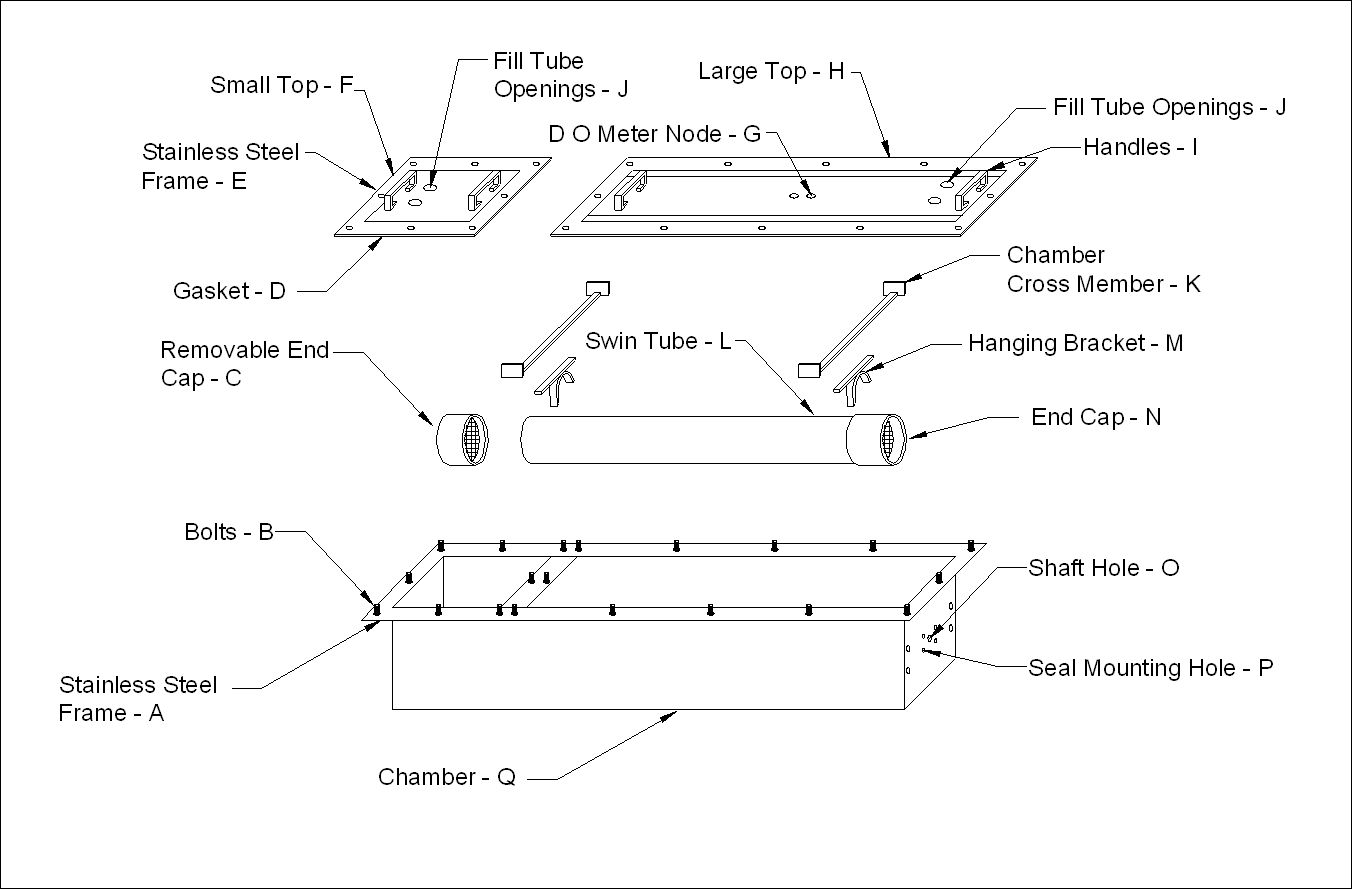 | Figure 3. Swim Tunnel System: Consisted of a Swimming Tube with Removable End Caps Mounted inside a Container Chamber with Removable Lids |
- The interior edges and corners of the container chamber were chamfered with 45° strips of 1 in tall for reducing turbulence. The strips were fastened and fused onto the inner walls of the swim section using adhesive. The lid section was made to have a dimension of 1 in larger than the dimension of the swim chamber in order to accommodate mechanical joints. Strips made of the same material were fastened around the outer periphery on the top side of the container chamber to form ledges for screw fasteners. The strips were fused onto the container chamber with adhesive and were positioned 0.25 in below the top edge of the container chamber. A groove of 0.25 in, 0.5 in wide was milled around the top lid plate to fit the top perimeter of the container chamber. Additional thru holes were made on the lid plate for mounting of fittings for water inlet and outlet, sensors, and other probing instruments. The lid was secured to the container chamber using screw fasteners.
2.4. Swim Tunnel Lid Construction
- The acrylic lid was made in two removable sections (Figure 3). Each section was composed of a rectangular metal frame made out of 2 ½ in flat stainless steel with a smaller section of clear acrylic bolted to its’ inside edge. The section closest to the motor was composed of an 11½ W x 43 ½ in L acrylic panel bolted to the inside edge of a 15 in W x 49 ¼ in L stainless steel frame. The acrylic panel was bolted to the rectangular steel frame using stainless steel bolts, nuts and washers. When the tunnel was in use, this section remained bolted to the tunnel except during cleaning or when the swim tube and propeller needed to be changed or repaired. The small top section on the end opposite the motor was used as an access door for the introduction or removal of fish. The door was composed of a 1½ in W x 13 ¾ in L acrylic panel bolted to a 15 in W x 16 ¼ in L stainless steel frame. The acrylic panel was bolted to the rectangular frame using stainless steel bolts, nuts and washers. An angle iron frame made out of 2 ½ in stainless steel was bolted to the outside top of the swim chamber. The free edge of the angle iron frame pointed out away from the chamber and served as a base for the metal frame and gasket on the edge of the sections of the top. An 3 ½ in L L-shaped bracket was attached to the frame 18 ½ in from the motor end of the tunnel to serve as an attachment point for the inclinometer. The inclinometer was used to accurately measure angular position between 0 and 90. The standard inclinometer only measured angles up to 45. Therefore, an extension was machined and fitted to the original ruled scale to allow measurement up to 90. A custom cut 2 ½ in neoprene gasket was fitted to the underside of the metal frame on each top section. When assembling the chamber for use, the metal frames on each door were slipped over the threaded ends of stainless steel bolts whose heads had been welded to the bottom side of the stainless steel frame on the outer edge of the top of the swim chambers. The chamber could then be sealed by tightening stainless steel nuts placed on each bolt. In order to facilitate calibration of the chamber, a second small door was built that had a flow meter wire, end cap, and flow meter permanently installed. Both top sections were fitted with two 3 in L tubes made out of ¾ in PVC pipe with a threaded nipple at the top. These tubes were used as water inlet and air relief ports. The tops of the tubes were fitted with a threaded brass cap. The caps could be easily tightened or removed by hand. The ¾ in threaded holes for the tubes were placed an equal distance from the sides of the top, 7 in apart. The holes for the tubes were placed within ½ in of the inside edge of the end section of the chamber. Two tubes were also placed in the top section on the opposite end of the chamber (removable door section). Either pair could serve as fill-tubes or vent tubes. The tunnel was always tilted at about 15 degrees when filled. This allowed trapped air to be easily removed by loosening the caps on the high end when filling swim chamber. A hole for an YSI oxygen probe was threaded into the center of the longer top section using a ¾ inch x 27 threads per in tap (standard audio threads). A plug with matching threads was made so the oxygen probe could be removed when not needed. The swim tube was where the fish actually swam. The swim tube was 5.5 in in diameter (inside) with ¼ in wall thickness. Two end caps with center holes were fastened to the tube to prevent the fish from escaping and a propeller was housed inside the swim tube at one end, and one of the end caps was made to be removeable. Two plastic grates were stacked and fastened in front of the propeller to separate the fish from the propeller and to function as a diffuser of turbulence introduced by the propeller. The end caps were constructed from a 6.0 in diameter clear acrylic tube with ¼ in wall thickness. The removable end cap kept the fish in the tunnel during tests and allowed adequate water flow. The end cap on the propeller end of the tube was fused to the main tube using the proper solvent. A stainless steel flat stock cross-member was attached approximately 9 in from each end of the chamber utilizing stainless steel screws. These cross members were constructed by TIG welding two short pieces of material perpendicular and vertical to the cross member at each end. The chamber walls were marked, drilled and tapped at the proper height to allow the tube to be suspended in the center of the chamber, both vertically and horizontally. Two stainless steel flat stock pieces were rolled to form bands around the outer circumference of the tube and a 0.265625 in hole taped into each end of each band. Another cross member was cut and TIG welded to this rolled band to facilitate mounting to the chamber cross member. The location of the holes was marked on the acrylic tube, then drilled and tapped to accept a 0.25 in stainless steel screw. A jam nut was installed on the screw, the screw was installed into the pipe flush with the inside surface, and the jam nut tightened to secure the tube to the mount. The two cross members were then bolted together using stainless screws, nuts and lock washers. This allowed the acrylic tube to be removed and cleaned quickly and easily. The top cross member, which was mounted to the chamber wall on both sides, was slotted where the short cross member was bolted to it thus allowing side to side adjustment of the tube. The swim tube was positioned 7 ½ in from the motor end of the tube. The brackets holding this end of the tube were located two and one half inches from the end of the tube. The end of the tube away from the motor was located 14 ½ in from the end of the chamber with the brackets located 2 ½ in from the end of the tube. The swim chamber system was secured to the angle iron tilting rack using four light-weight metal angles which hooked over and were bolted to the acrylic braces glued around the bottom of the chamber. The chamber rested on a rubber gasket inside the angle iron bottom frame, which reduced the possibility of damage when the chamber was full of water.
2.5. Propeller Shaft Assembly Design
- The swim tunnel was fitted with a Dayton DC variable speed motor with external control unit (Model 2Z846D, Figure 4). A spider coupling was used to connect the propeller shaft to the motor. The propeller shaft was constructed using a precision machined 5/8 in # 304 stainless steel shaft (Mackmaster-Carr Supply Co., Atlanta, Georgia). The shaft was supported on the motor end by the motor shaft and the spider gear coupling. The shaft was supported on the outside and inside of the end section of the chamber by a 2-eared pillow block bearing bolted to a stainless steel plate and the custom seal bolted to the inside of the end wall of the chamber, respectively. A 6 in plastic electric aerator propeller (Aquacenter, Greenville, MS) was trimmed to fit just inside the swim tunnel end cap with minimum clearance and fastened to the end of the shaft with a roll pin.
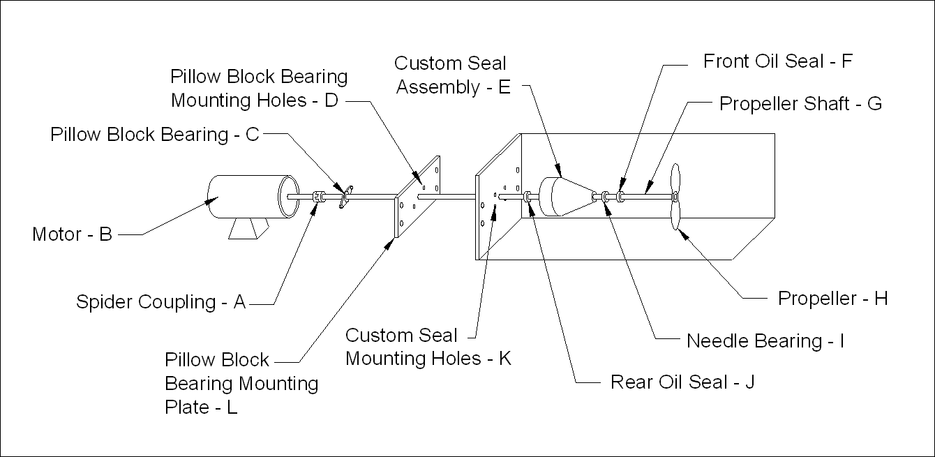 | Figure 4. Propeller shaft assembly |
2.6. Custom Seal Design
- The custom seal assembly was constructed using an 3 ½ in L x 3 ½ in W acrylic round stock. A special jig was made out of steel to hold the round stock in alignment so it could be machined in a lathe. A small round groove was machined into the motor end of the round stock 0.37 in from its outer edge to hold an O-ring, which made the seal assembly water tight when fastened to the chamber. A 3/4 in hole was drilled through the center of the acrylic round stock to allow passage of the 0.63 in precision ground stainless steel shaft. On the propeller end of the seal assembly, the 3/4 in hole was drilled out to a size just under 1.005 in wide x 1 3/8 in deep so a 1 in needle bearing could be pressed into it. The needle bearing rested on the ridge left when the 3/4 in hole was drilled out to approximately 1 in. The top of the 1 in hole was drilled out to a size just slightly less than 1.165 inches x ¼ inch deep so a 1.165 in automotive oil seal could be pressed into it. The 3 ½ in acrylic round stock was tapered beginning 1 in in from the back edge (motor side) to a point 0.12 in up from the edge of the propeller shaft at the end away from the motor. A grease fitting was placed behind the end oil seal so that the small cavity could be filled with grease. The advantages of the new seal and support system were as follows: it improved the ability to level and align (center) the shaft in the tunnel; it greatly increased the stability of the shaft when running at slow and high speeds; and it reduced frictional heat build up in the chamber during tests.
3. Tilting Tunnel Calibration
- The water flow rates were calibrated using a Swoffer Instruments Current Sensor (Model 2100) attached to a special removable end cap. The readings obtained with the flow meter were equated to the rpm’s of the propeller shaft. A flow rate calibration chart was made allowing the flow rate to be set using the digital readout of the rpm sensor. It was necessary to make certain that changing the angle of the swim tunnel would have no impact on the flow rates as determined at the zero angle (horizontal). The tunnel was tilted and recalibrated for each angle in 5 increments up to ±30 and then 15 increments to ±60. An analysis of variance was used to determine that there was no significant difference in the flow rate (cm/s) at any angle tested (Figure 5). A linear model was fit to the flow rate data for speeds of 0-90 cm/s. The relationship between speed and rpms at any angle in this swim tunnel was described by the equation:Y = 11.2477 X + 8.4735where Y was the rpms and X was the speed (R2 = 0.99).
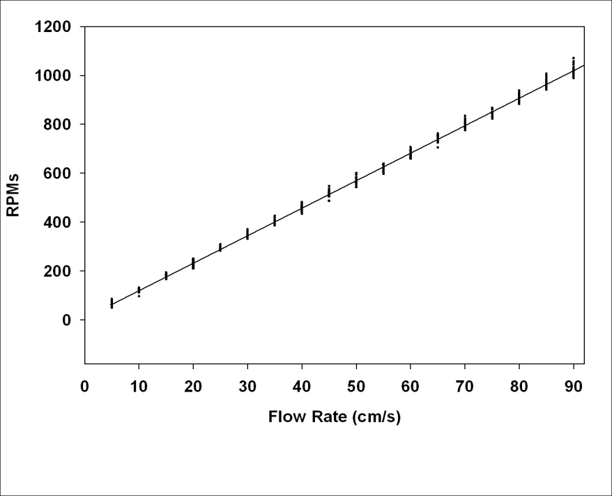 | Figure 5. Calibration curve for rpm gauge |
4. Tilting Tunnel Operation
- Beecham et al. (2013) demonstrated the use of the tilting tunnel respirometer when studying blue and channel catfish swimming. Ten blue and channel catfish were swum at each of nine angles (0°, ±15°, ±30°, ±45°, ±60°) using a critical swimming speed (Ucrit) protocol. Both species demonstrated a linear decrease in Ucrit with a corresponding increase in swimming angle (Figure 6). However, blue catfish showed no significant differences in swimming performance compared to horizontal swimming when the angle of decline increased, while channel catfish demonstrated a non-linear swimming ability with an increasing decline angle (Figure 7). The results of this study indicate that measurable differences exist between swimming performance of these two closely related species relative to angles of incline or decline.
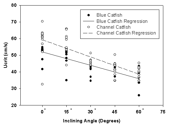 | Figure 6. Linear regressions of juvenile blue and channel catfish critical swimming speed at inclining angles. The “*” indicates a significant difference between blue and channel catfish at that angle. Reprinted from Beecham et al. 2013 |
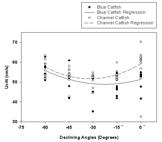 | Figure 7. Quadratic regressions of juvenile blue and channel catfish critical swimming speed at declining angles. The “*” indicates a significant difference between blue and channel catfish at that angle. Reprinted from Beecham et al. 2013 |
5. Conclusions
- The basic tunnel design of Blazka et al. (1960) was modified by lengthening the respirometer (60 inches), thus allowing a longer (45 inches) tube and a longer working section (39 inches). Other significant improvements included: the design of an innovative seal and shaft support system; the redesign and streamlining of the swim tube mounting system; the addition of an easily read inclinometer for setting angles; the adaptation of an rpm gauge to simplify setting water flow speeds; and the design of an A-frame and tilting rack assembly for supporting and safely tilting the swim chamber. The swim tunnel respirometers held 100 L (26.41 gal) of water and could generate water currents from 5-160 cm/s using a 6 in diameter tube. The modifications made when building this swim tunnel successfully reduce leakage and air inclusions enabling the measurement of a fish’s oxygen usage over time and the calculation of metabolic rate and cost of transport at various speeds at angles from 0-60° on both inclines and declines. The swim tunnel proved to be durable, dependable, and easy to use. This type of swim tunnel allows determination of swimming abilities and efficiencies of fishes over a wide range of non-horizontal swimming angles.
ACKNOWLEDGMENTS
- This research was supported by the Thad Cochran National Warmwater Aquaculture Center, Mississippi State University, through a cooperative agreement with the USDA Agricultural Research Services (No. 58-6402-2-0036). A special thank you is extended to Jeff Doler who was instrumental in the construction of this swim chamber. Donnie Rutherford and Chris Wilcutt are thanked for creating the Autocad drawings of this swim tunnel and its specialized features.