-
Paper Information
- Next Paper
- Previous Paper
- Paper Submission
-
Journal Information
- About This Journal
- Editorial Board
- Current Issue
- Archive
- Author Guidelines
- Contact Us
Science and Technology
p-ISSN: 2163-2669 e-ISSN: 2163-2677
2013; 3(4): 105-111
doi:10.5923/j.scit.20130304.02
Heat Transfer Enhancement in Heat Pipe Using TiO2 Nanofluid with N-Butanol
 Abstract
 Reference
 Full-Text PDF
 Full-text HTML
R. Reji Kumar, M. Narasimha, K. Sridhar
Lecturer, School of Mechanical and Industrial Engineering, Bahirdar University, Bahirdar, Ethiopia
Correspondence to: R. Reji Kumar, Lecturer, School of Mechanical and Industrial Engineering, Bahirdar University, Bahirdar, Ethiopia.
| Email: |  |
Copyright © 2012 Scientific & Academic Publishing. All Rights Reserved.
This study presents the improvement of thermal performance of heat pipe using TiO2nanofluid with aqueous solution of n-Butanol. The nanofluids kept in the suspension of conventional fluids have the potential of superior heat transfer capability than the conventional fluids due to their improved thermal conductivity. In this work, the TiO2nanofluid which has a 50 nm size with a concentration of 100 mg/lit is kept in the suspension of the de-ionized (DI) water and an aqueous solution of n-Butanol and these fluids are used as a working medium in the heat pipe. The study discusses about the effect of heat pipe inclination, type of working fluid and heat input on the thermal efficiency and thermal resistance. The experimental results are evaluated in terms of its performance metrics and are compared with that of DI water.
Keywords: TiO2Nanofluid, Aqueous Solution of N-Butanol, Heat pipe, Thermal Efficiency, Thermal Resistance
Cite this paper: R. Reji Kumar, M. Narasimha, K. Sridhar, Heat Transfer Enhancement in Heat Pipe Using TiO2 Nanofluid with N-Butanol, Science and Technology, Vol. 3 No. 4, 2013, pp. 105-111. doi: 10.5923/j.scit.20130304.02.
Article Outline
1. Introduction
- Heat pipes were developed especially for space applications during the early 60´ by the NASA. One main problem in space applications was to transport the temperature from the inside to the outside, because the heat conduction in a vacuum is very limited. Hence there was a necessity to develop a fast and effective way to transport heat, without having the effect of gravity force. The idea behind is to create a flow field which transports heat energy from one spot to another by means of convection, because convective heat transfer is much faster than heat transfer due to conduction. Nowadays heat pipes are used in severalapplications, where one has limited space and the necessity of a high heat flux. Of course it is still in use in space applications, but it is also used in heat transfer systems, cooling of computers, cell phones and cooling of solar collectors.Figure 1.Shows the schematic diagram of heat pipe.Heat pipes and their applications in thermal management have been studied for decades. They constitute an efficient, compact tool to dissipate substantial amount of heat from various engineering systems including electroniccomponents. Heat pipes are able to dissipate substantial amount of heat with a relatively small temperature drop along the heat pipe while providing a self-pumping ability due to an embedded porous material in their structure. A limiting factor for the heat transfer capability of a heat pipe is related to theworking fluid transport properties. In order to overcome this limitation, the thermophysical properties of the fluid can be improved. An innovative way to enhance liquid thermal conductivity is the dispersion of highly conductive solid nanoparticles within the base fluid.
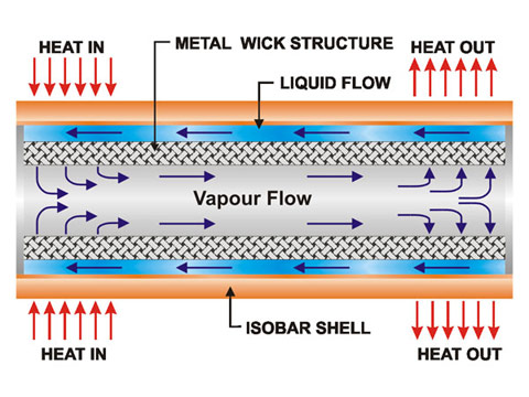 | Figure 1. Schematic view of heat pipe |
2. Literature Review
- The heat transfer characteristics of the heat pipe have been studied by a number of researchers. Lin et al.[1]experimentally analyzed the two-phase flow and heat transfer of R141b in a small tube. Song et al.[2] discussed about the heat transfer performance of axial rotating heat pipes at steady state conditions. Xuan et al.[3] performed experiment on a flat heat pipe under different heat fluxes, inclinations and theamount of the working fluid. Liu et al.[4] considered the effects of the length of the evaporator, vapour temperature on the critical values of the upper and lower boundaries.Due to the useful features of a nanofluid, various research groups [5–16] have tried to engage it within a heat pipe and study the subsequent thermal enhancement experimentally. Different nanoparticles such as silver[5,10,13,15], CuO [7,11], diamond[8,14], titanium[6,9], nickel oxide[12], and gold[16] have been utilized within the heat pipe working fluid. Theimproved thermal performance is observed through a reduction in thermal resistance[5,8–11,13,15,16], a drop in thetemperature gradient along the heat pipe[5,14,15], an increase in the heat pipe efficiency[6], and an enhancement in the overall heat transfer coefficient[12]. In some studies[7,11], the existence of an optimum amount of nanoparticle mass concentration providing the highestthermal performance has been established. Liu et al.[11] have shown that the heat pipe operating pressure has a significant effect on the thermal performance. In another study, Riehl [12] has observed that a higher heat transfer coefficient can be seen when using nanoparticles in water under low heat input conditions. Tsaia[16] investigated theinfluence of particle size on the heat pipe thermalperformance. From the analysis, it has been found that the nanofluids have the higher heat transfer capacity than the conventional working fluids and also it reduces the overall thermal resistance between the evaporator and the condenser. It is in this direction, a working fluid which is the combination of copper nanoparticle and the aqueous solution of long chain alcohols has been explored in order to enhance the thermal performance of the heat pipe.All the types of heat pipes have a common problem of heat transfer limitation. These limitations determine themaximum heat transfer rate for a particular heat pipe under the normal working conditions. In heat pipe design, the capillary limit and the boiling limits are important under the normal working conditions. The surface tension is an important key factor for capillary limit. The surface tension of all the pure liquids is normally decreasing with increase in temperature, as the liquid moves along the interface towards the cooler condenser zone. The working fluids currently available for heat pipes have negative surface-tension gradients with temperature, that are unfavourable for the spreading or re-wetting on a heated surface, and therefore, the operating temperature and the heat load of heat pipe systems are limited. The heat pipe systems also suffer from operational instability problems because of thecharacteristics of the negative surface tension gradient withtemperature[17]. For medium temperature applications, water is used as a working fluid, due to its availability, cost, safety, easiness to handle and high surface tension. At elevated temperatures the surface tension of the water also decreases rapidly with increase in temperature. The heat transfer capability of the all heat transfer devices including heat pipe is limited by the working fluid transport properties. To overcome these limitations, the thermo physical properties of the working fluid have to be improved. The heat transfer rate of heat transfer devices can be improved by adding additives to the working fluids to change the fluid transport properties and flow features. One of the methods is to use the aqueous solutions of alcohols, with chain lengths longer than four carbon atoms. Vochten and Petre[18] experimentally revealed that the surface tension of aqueous solutions of alcohols, with chain lengths longer than four carbon atoms, have a positivegradient with temperature when the temperature exceeds a certain value. The stable working fluid circulation in a heat pipe is achieved through the capillary pressure head developed by the wick structure. The maximum capillary head developed in the heat pipe must be more than the various pressure losses along the vapour-liquid path which includes liquid pressure drop, vapour pressure drop, gravity pressure drop and pressuredrop in wick structure. It is sufficient that only a small amount of the long-chain alcohols, in the order of 10-3 mole per liter, is required to change the surface tension characteristics of water without affecting the other bulk properties of the water[19].
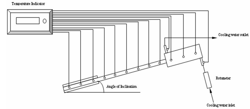 | Figure 2. Schematic diagram of experimental setup |
3. Experimental Setup
- The schematic diagram of the heat pipe under consideration and the thermocouple locations are shown in Figure. 2. The experimental set up was made from a copper tube with an inner diameter of 20.8 mm and outer diameter 22 mm Two layers of stainless steel screen mesh wick has been used to improve the capillary action. The length of the evaporator, adiabatic and condenser sections are 150,300 and 150 mm respectively. The heat pipe is charged with 30 ml of working fluid, which approximately corresponds to the amount required to fill the evaporator. The wall temperature distribution of the heat pipe in adiabatic zone is measured using six evenly spaced copper constantan (k-type) thermocouples with an uncertainty of ±0.1℃, at an equal distance from the evaporator. In addition the thermocouples are also located in evaporator surface (three locations), condenser surface (three locations), inlet and outlet of the condenser jacket. The electrical power input is applied at the evaporator section using cylindrical electric heater attached to it with proper electrical insulation and the heater is energized with 230V AC supply using a variac and measured using a power transducer with an uncertainty of ±1 W. Water jacket has been used at the condenser end to remove the heat from the pipe. The heat pipe has the ability to transfer the heat through the internal structure. As a result, a sudden rise in wall temperature occurs which could damage the heat pipe if the heat is not released at the condenser properly. Therefore, the cooling water is circulated first through the condenser jacket, before the heat is supplied to the evaporator. The condenser section of the heat pipe is cooled using water flow through a 150 mm long jacket with an inner diameter of 30 mm and outer diameter of 36 mm. The water flow rate is measured using a rotameter on the inlet line to the jacket that has an uncertainty of ±1% and the flow rate is kept constant at 0.08 kg/min. The inlet and outlet temperatures of the cooling water are measured using two copper constantan thermocouples. The adiabatic section of the heat pipe is completely insulated with the glass wool. The amount of heat loss from the evaporator and condenser surface is negligible.
4. Experimental Procedure
- The experiments are conducted using three identical heatpipes which are manufactured as per mentioned dimensions. One of the heat pipes is filled with de-ionized water, secondone with TiO2nanofluid and third one with the aqueoussolution of n-Butanol with TiO2nanofluid. The power inputto the heat pipe is gradually raised to the desired power level. The surface temperatures at six different locations along the adiabatic section of heat pipe are measured at regular time intervals until the heat pipe reaches the steady state condition. Simultaneously the evaporator wall temperatures, condenser wall temperatures, water inlet and outlet temperatures in the condenser zone are measured. Once the steady state is reached, the input power is turned off and cooling water is allowed to flow through the condenser to cool the heat pipe and to make it ready for further experimental purpose. Then the power is increased to the next level and the heat pipe is tested for its performance. Experimental procedure is repeated for different heat inputs (30, 40, 50, 60 and 70 W) and different inclinations of pipe (0o, 15°, 30°, 45°, 60°, 75° and 90°) to the horizontal and observations are recorded. The output heat transfer rate from the condenser is computed by applying an energy balance to the condenser flow. The vacuum pressure in the inner side of the heat pipe is monitored by vacuum gauge, which is attached in the condenser end of the heat pipe.
5. Results and Discussions
5.1. Effect of Heat Pipe Inclination in Efficiency
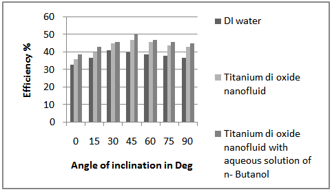
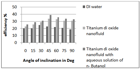 | Figure 3. Efficiency for different inclinations at 30W heat input |
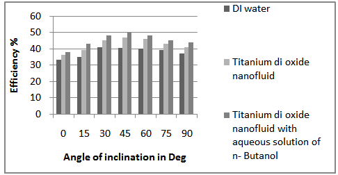
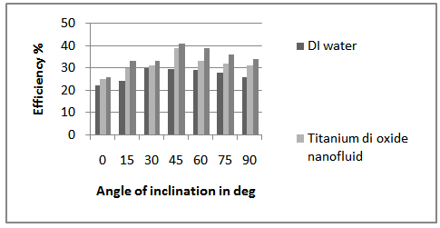 | Figure 4. Efficiency for different inclinations at 40W heat input |
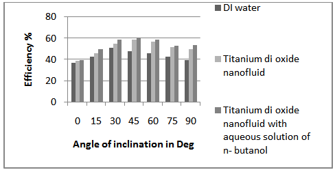
 | Figure 5. Efficiency for different inclinations at 50W heat input |
 | Figure 6. Efficiency for different inclinations at 60W heat input |
 | Figure 7. Efficiency for different inclinations at 70W heat input |
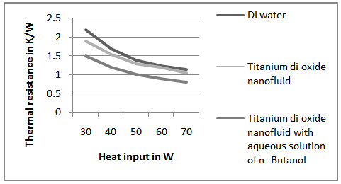
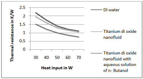
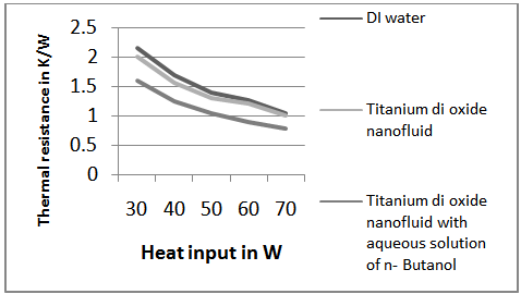
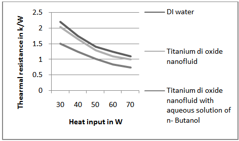
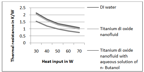
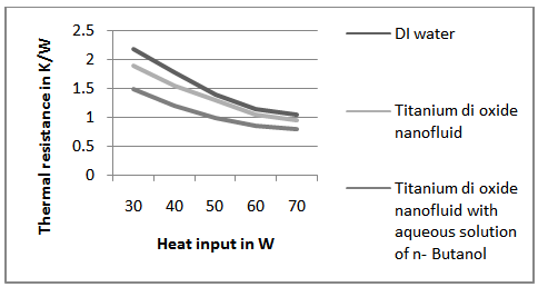
5.2. Effect of Thermal Resistance
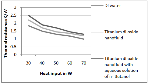 | Figure 8. Thermal resistance of heat pipe for 0° inclination |
 | Figure 9. Thermal resistance of heat pipe for 15° inclination |
 | Figure 10. Thermal resistance of heat pipe for 30° inclination |
 | Figure 11. Thermal resistance of heat pipe for 45° inclination |
 | Figure 12. Thermal resistance of heat pipe for 60° inclination |
 | Figure 13. Thermal resistance of heat pipe for 75° inclination |
 | Figure 14. Thermal resistance of heat pipe for 90° inclination |
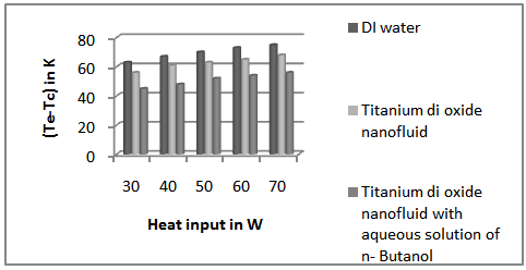
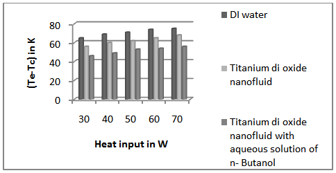
5.3. Variation of Temperature Difference between Evaporator and Condenser
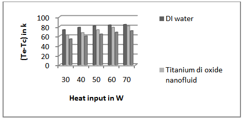 | Figure 15. Variation of (Te-Tc) for 0° inclination |
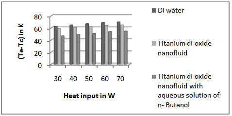
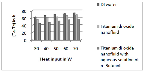 | Figure 16. Variation of (Te-Tc) for 15° inclination |
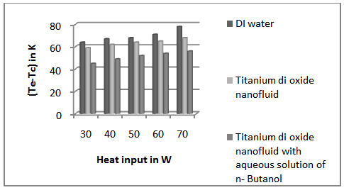
 | Figure 17. Variation of (Te-Tc) for 30° inclination |
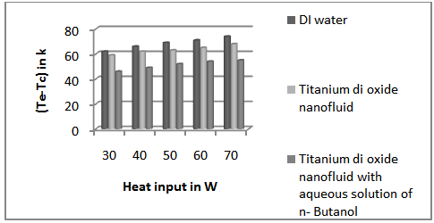
 | Figure 18. Variation of (Te-Tc) for 45° inclination |
 | Figure 19. Variation of (Te-Tc) for 60° inclination |
 | Figure 20. Variation of (Te-Tc) for 75° inclination |
 | Figure 21. Variation of (Te-Tc) for 90° inclination |
6. Conclusions
- In this study, the thermal performances of the cylindrical heat pipe with wire mesh are experimentally investigated using the DI water, TiO2nanofluid and TiO2nanofluid with aqueous solution of n-Butanol as working fluids. To evaluate the thermal performance of the heat pipe using the TiO2 nanofluid and TiO2nanofluid with aqueous solution of n-Butanol, the thermal efficiency and the thermal resistances between the evaporator and the condenser regions are measured and compared with the heat pipe using DI water. Based on the experimental results, it is found that the thermal efficiency of TiO2nanofluid with aqueous solution of n-Butanol is higher than the base fluid DI water and TiO2nanofluid and the thermal resistance also reduces to three fourth of base fluid. The results show that the thermal performances of the heat pipe may be enhanced by adding a very small amount of long chain alcohol which gives the better performance than the conventional working fluid and nanofluid. This may be due to the reason that, the dilute aqueous solution of n-Butanol which is having a positive surface tension gradient with temperature gives rise to an increased value of the capillary limit and the boiling limit of the heat pipe along with the nanofluid.