Fuad Mammadov
Azerbaijan State Oil Academy, Azerbaijan Republic, AZ1010, Baku city, D. Aliyeva 227
Correspondence to: Fuad Mammadov, Azerbaijan State Oil Academy, Azerbaijan Republic, AZ1010, Baku city, D. Aliyeva 227.
| Email: |  |
Copyright © 2012 Scientific & Academic Publishing. All Rights Reserved.
Abstract
The paper concerns to the usage of the heat exchanging apparatus being utilized during mechanical cleaning of the oily waters by mechanical ways. Here, as one of the main elements of the solar energy plant having focusing concentrator, general thermal and energy calculations of the heat exchanging apparatus were presented.
Keywords:
Heat exchanger, Heat-energy calculation, Solar energy, Parabolic trough solar plant, Initial oily waste water treatment
Cite this paper: Fuad Mammadov, Thermotechnical Calculation of Heat Exchanger for Solar Energy Plants, Science and Technology, Vol. 3 No. 2, 2013, pp. 55-60. doi: 10.5923/j.scit.20130302.02.
1. Introduction
At present in the onshore oil wells, the cleaning of the oily waters is one of the major questions. The waters wasted by the oil and oil productions have a great deal of hazardous toxic matters and heavy metals in the content which can waste other neighboring water basins by leading to huge ecological damages. At the result the medical hygienic disaster influences on the environment including fauna, flora and so on. Solution of this question will serve the collection of the oil for export and improve the ecological condition. The most profitable way among other for cleaning oily waste is the mechanical method. While the application of the mechanical method utilization of the heat energy increases the productivity much more. For exploitation of the heat mainly heat-exchanging apparatuses are need for the processes. During technological processes where solar energy is applied by using focusing concentrators, the exploitatin of heat-exchanging apparatus has great importance. The main parameters of the heat-exchangers are, hight productivity, light weight (metal capacity) and minimum heat loss. The heat axchangers are divided into two groups: recuperative and regenerative heat-exchanging apparatuses. The heat-exchanging apparatuses which are utilized in the oil fields and in other industry sectors should be recuperative type. Different constructions of such type heat-exchangers were applied in the high temperatured solar energy plants for crude oil treatment and oily waters cleaning processes[1,2]. From technological and constructive facets recuperative heat exchangers are too reliable. Heat transfer in the recuperative heat exchanger from one medium to other happens in the hard layer. That’s why between any two kind matters heat-exchanging process is possible. Therefore thermotechnical calculation of the process is to be taken into considration to study the heat-exchanging process in advance in the heat exchanging apparatus between heat transfer and oily waste. For this purpose the below mentioned parameters have to be defined.
2. Experimental Procedure and Results
During experiment for density of solar radiation-W/m2, air temperature ℃, wind speed-m/sec is measure.For checking validity of the plant before in the initial experiments as the heating (water) and being heated (oily waste water) matters water-water was accepted[3]. Because of temperature obtained not being convected due to sun rays reflected from concentrator solar reactor was put inside of molybdenum glass pipe with  diameter, thickness
  , length of
 . Integral ray transmition of molybdenum glass pipe in solar spectrum
  . In order to increase efficiency and to obtain isotermic condition reactor surface adsorbing solar rays was coated with a selective black chrome surface and surrounded with clear glass tubes
 . The distance between glass and steel pipes was vacuumized that gives opportunity heat loss to be decreased to minimum. Generally because of not heat loss in whole system where heat transfer moves glass wool and special cover were used. Chromel-copel thermo pair calibrated were put on suitable places to measure temperature difference on internal and external surface of solar reactor, glass pipe, heat exchanger, and to measure temperature of oil and heat transfer in entrance and exit. Exits of thermo pair were jointed to digital potentiometer. According to potentiometer’s factor temperatures are found in calibration table. Water is accepted as heat transfer.
3. Thermotechnical Calculation of Heat Exchanger
The heat loss is to be determined which happens by irradiance and convection ways in the resin pipes which joins the out let of the solar reactor and inlet of the heat-exchanger in the solar energy plants having focusing consentrators. For this purpose the following formula may be utilized. ● Corespondingly the heat loss on the surface of joining communication lines (rubber tube) which happens by irradiance ways can be calculated.  | (1) |
Here, dcext=0,032 m – external diameter of the joining communication lines; lc=2,5 m- total length of the joining communication lines; εc=0,4- blackness of the joining communication lines; тc=52,5℃- average surface temperature of the joining communication lines.  .● The heat loss happing by the convection ways on the surface of joining communication lines,
 | (2) |
Here, αc=12 W/(m2℃)- heat transfer coefficient to the environment in the joining communication lines surface .  The rate of the heat being transfered to the heated liquid at the begining case, W;
 | (3) |
Square of “annular tube” type counter-current heat exchanger must be calculated (fig 1). Heat transfer, (water) with the flow rate , running through the cupper pipe with round cross-section having
  heat conductivity comes into the heat-exchanger at
  temperature running through copper pipe with round cross-section oily waste water is heated from
  temperature to
  temperature. Flow rate of the oily waste water being heated is
  .Quantity of heat transfered to the oily waste water being heated is ditermined:
 | (4) |
The temperature of heat transfer in heat exchanger exit: | (5) |
Average temperature of heat transfer:  | (6) |
Physical properties of heat transfer and oily waste water corresponding to the average temperature are selected from the references[4,5].Average temperature the oily waste water being heated: | (7) |
Heat transfer’s rate of movements: | (8) |
Rate of movement of the oily waste water being heated: | (9) |
Reynolds criteria for heat transfer: | (10) |
Nusselt number for heat transfer[6]: | (11) |
Here  is, that’s why
 :Average temperature of wall surface:
 | (12) |
According to this temperature that’s determined from the table 
 - ratio of heat transfer from heat transfer to pipe wall surface:
 | (13) |
Reynolds criteria for oily waste water being heated: | (14) |
Here - - equivalent diameter of tube:
 | (15) |
The temperature of wall surface: Accepting,Nusselt number is calculated:
 | (16) |
 - ratio of heat transfer from wall to the oily waste water being heated:
  | (17) |
Ratio of heat dissipation for heat exchanger[7]:  | (18) |
Average logarithmic temperature drop:  | (19) |
Density of heat flow in 1 m tube: | (20) |
Length of heat exchanger pipe: | (21) |
Square of heating surface: | (22) |
If we accept the length of one section  amount of heat exchanger’s sections:
 | (23) |
If we accept liquid’s movement to be direct-flow in heat exchanger, average logarithmic temperature drop will be: | (24) |
Density of heat flow: | (25) |
Length of heat exchanger pipe: | (26) |
Heating Surface Square of heat exchanger with direct-flow:  | (27) |
Sections’ amount of heat exchanger with direct-flow: | (28) |
Heat exchanger was covered by isolation coat with  and
and  heat conductivity ratio. Additionally this isolation layer was wound by an cork isolation layer with
  thickness and
 ,
,  heat conductivity ratio. Heat conductivity ratio from cork isolation to air
 . Heat amount lost in
  of heat exchanger, at the same time temperature of layer surfaces must be determined:Heat dissipation ratio is determined in cylindrical wall with many layers by formula 29[8]:
  | (29) |
Density of heat flow lost in  pipe:
pipe: | (30) |
Temperatures of layer surfaces are determined.Temperature of the first layer surface: | (31) |
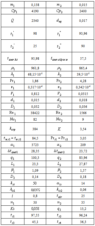
Table 1. Calculation’ results were given due to experiments carried out dealing with heat-exchanger
 |
| |
|
Temperature of the second layer surface: | (32) |
Temperature of the third layer surface: | (33) |
Temperature of cork isolation’s external surface: | (34) |
In the table 1 calculation’ results were given due to experiments carried out dealing with heat-exchanger. 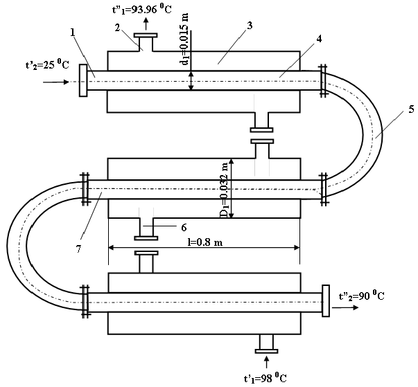 | Figure 1. Principial sceme of “annular tube” type counter-current heat exchanger. 1 - oily waste input, 2 – heat transfer out, 3 – outside tube, 4 - internal tube, 5 – bend, 6 – flange, 7 - continuation of internal tube |
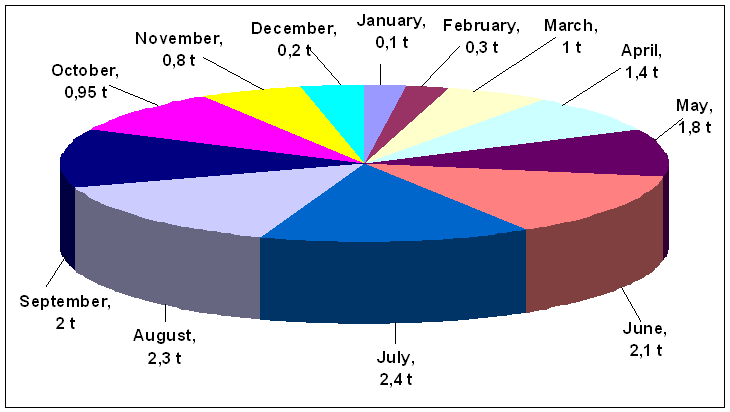 | Figure 2. Annual force of the solar energy plant for oily waste water treatment due to experiments carried out (to months) |
4. Conclusions
The calculations show that the utilization of heat-exchanger in the solar energy plants is effective from energy facet. Thus, the refined and cleaned water which is heated in the heat-exchanger can be used for watering purpose in agriculture field, for cooling the trubines in the heatpower stations, for washing the cars in the washing stations. At the same time this water is used as the low temperatured heat transfer in the solar energy plants. Like the water which has the proper technical parameters it can be applied in the active heliosystems.
Nomenclature
 - Heat transfer flow,
  .
. - Oily waste water flow,
  .
. - Heat capacity of heat transfer,
  .
. - Heat capacity o oily waste water,
  .
. - Amount of heat being transferred by oily waste water,
  .
. - Equivalent diameter of heat exchanger pipe,
  .
.  - Entrance temperature of heat transfer,
  .
. - exit temperature of heat transfer,
  .
. - Entrance temperature of oily waste water,
  .
. - Exit temperature of oily waste water,
  .
. Average temperature of heat transfer,
  .
. Average temperature of oily waste water,
  .
. - Density of heat transfer at average temperature,
  .
. - Density of oily waste water at average temperature,
  .
. - Heat conductivity of heat transfer at average temperature,
  .
. - Heat conductivity of oily waste water at average temperature,
  .
. - Prandtle criteria of heat transfer at average temperature.
 - Prandtle criteria of oily waste water at average temperature.
 - Kinematics viscosity ratio of heat transfer at average temperature,
  .
. - Kinematics viscosity ratio of oily waste water at average temperature,
  .
. - Heat transfer’s movement speed,
  .
. - Oily waste water’s movement speed,
  .
. - Internal diameter of pipe in which heat transfer runs,
  .
. - External diameter of pipe in which heat transfer runs,
  .
. - Internal diameter of pipe in which oily waste water runs,
  .
. - External diameter of pipe in which oily waste water runs,
  .
. -Reynolds criteria for heat transfer.
 - Reynolds criteria for oily waste water.
  - Nusselt criteria for heat transfer.
 - Nusselt criteria for oily waste water.
 - Heat conductivity ratio of copper pipe in which heat transfer runs,
  .
.  - Heat dissipation ratio of heat exchanger,
  .
. Average temperature of wall surface,
  .
. Prandtle criteria of average temperature of wall surface,
  .
. - Ratio of heat dissipation from heat transfer to pipe’s wall surface,
  .
. - Ratio of heat dissipation from pipe’s wall surface to oily waste water,
  .
. Average logarithmic temperature drop for heat exchanger with direct-flow,
  .
. Average logarithmic temperature drop for heat exchanger with counter-current,
  .
. - Density of heat-flow in each 1 m pipe of heat exchanger with direct-flow,
  .
. - Density of heat-flow in each 1 m pipe of heat exchanger with counter-current,
  .
. - Pipe length of heat exchanger with direct-flow,
  .
. - Pipe length of heat exchanger with counter-current,
  .
. - Square of heating surface for heat exchanger with direct-flow,
  .
. - Square of heating surface for heat exchanger with counter-current,
  .
. -diameter of the first isolation layer (glass wool) on the pipe,
  .
. Diameter of the second isolation layer (cork) on the pipe,
  .
. Ratio of heat conductivity of the steel pipe in which oily waste water runs,
  .
.  Ratio of cork isolation’s heat dissipation to air,
  .
. Heat conduction ratio of the first isolation,
  .
.  Heat conduction ratio of the second isolation,
  .
.  - Length of a section,
  .
. Air temperature,
  .
.  - Sections amount of heat exchanger with direct-flow.
  - Sections amount of heat exchanger with counter-current.
 - Ratio of heat transfer from many layered (isolation) cylindrical wall,
  .
. Density of heat-flow lost in each 1m of heat exchanger’s pipe,
  .
. Temperature of the first layer surface,
  .
. Temperature of the second layer surface,
  .
. Temperature of the third layer surface,
  .
. Temperature of the fourth layer surface,
  .
.
References
| [1] | Safarov G I, Mammadov A S. Technology of oil and gaz treatment. Baki: Maarif; 2000. |
| [2] | Salavatov T.Sh, Mammadov F.F. Panahov E.A. Alternative and renewable energy sources application facilities in the cleaning of oily waste water. Oil Industry. 2011, Vol 6. pp.46-49. |
| [3] | Mammadov F.F. Use of solar energy in Azerbaijan and modern solar energy plants, Progress, Baku, 2011, p.204. |
| [4] | Vargaftik N B. Directory on heat physics properties of gaz and liquid. Moscow: Fizmatgiz; 1979. |
| [5] | Vucalovich M P. Thermodynamic properties of water and water vapour. Moscow: Mashgiz; 1958. |
| [6] | Mikheyev M A, Mikheyeva I M. Foundations of heat-transfer process. Moscow: Energiya; 1973. |
| [7] | Berman S S. Calculation of heat exchanger of turbo-installation. M.L: Gosenergoizdat; 1962. |
| [8] | Nashokin V V. Technical thermodynamics and heat transfer. Moscow: Vishaya shkola; 1980. |
 Abstract
 Reference
 Full-Text PDF
 Full-text HTML