Chigbogu G. Ozoegwu1, Sam N. Omenyi1, Chinonso H. Achebe1, Chigozie F. Uzoh2
1Department of Mechanical Engineering Nnamdi Azikiwe University PMB 5025, Awka
2Department of Chemical Engineering, Nnamdi Azikiwe University, Awka, Nigeria
Correspondence to: Chigbogu G. Ozoegwu, Department of Mechanical Engineering Nnamdi Azikiwe University PMB 5025, Awka.
| Email: |  |
Copyright © 2012 Scientific & Academic Publishing. All Rights Reserved.
Abstract
A new delay differential equation (DDE) which is non-periodic is presented to govern circular feed end-milling. This equation is considered extended or more generalized since special simplifications lead to the classical periodic DDE model for linear feed end-milling and a new periodic DDE model postulated to govern circular end-milling. Stability analysis of both periodic DDE is conducted using a modified full-discretization map and directly compared on the same cutting parameter plane of spindle speed and depth of cut. It is found that stability of regenerative vibration of both periodic mechanical models is identical. This means that curvature has negligible effect on stability thus circular end-milling can almost accurately be represented as straight-line feed end-milling.
Keywords:
Circular Feed End-Milling, Linear Feed End-Milling, Angular Feed Speed, Chatter Stability
Cite this paper: Chigbogu G. Ozoegwu, Sam N. Omenyi, Chinonso H. Achebe, Chigozie F. Uzoh, Stability of Circular Feed End-Milling Compared with That of Linear Feed Equivalent, Science and Technology, Vol. 3 No. 1, 2013, pp. 17-23. doi: 10.5923/j.scit.20130301.02.
1. Introduction
The life and performance of machine tools is compromised by vibrations called chatter. The most detrimental of machine tool vibrations is the regenerative chatter that is triggered by small perturbations and sustained by unfavourable cutting parameter combinations. Regenerative chatter is caused by regenerative effects (or effects of waviness) on two out-of-phase profiled surfaces of perturbed consecutive tool passes. Thus tool motion in a past time affects the present motion. This feedback of delay effects can introduce tool instability since without it the tool is intrinsically stable under positive damping. The aforementioned feedback of delay effects means that regenerative chatter is modelled by delay differential equations (DDE’s). The DDE governing the milling process is parametrically excited because of time-dependence angular position of the cutting edges.The milling process is extensively modelled with straight-line (or linear) feed[1-6]. The time-dependent angular position of the cutting edges under straight line feed is periodic leading to periodic DDEs for linear feed milling. Situations needing polar cuts arise in real life but it seems that linear feed end-milling equation has so far been presumed applicable in this situation as well. In this work modelling of circular end-milling is conducted to reveal the effects curvature could have on regenerative chatter stability. A non-periodic DDE results, which under a rational simplification becomes a periodic DDE. This periodic DDE is used as a model for circular end-milling. Simplification of infinitely large radius imposed on the non-periodic DDE leads to a periodic DDE identical with those seen in[1, 6], which are derived on the basis of straight-line feed. The non-periodic DDE for circular end-milling can thus be considered more general for end-milling. This forms the centre of novelty of contribution of this work.Stability of the new periodic mechanical model for circular end-milling is compared with that of a classical periodic mechanical model of linear feed end-milling to reveal the effects of curvature on regenerative chatter stability. It was found that presence of curvature in circular feed end-milling model has no meaningful effect on regenerative chatter stability. Thus a circular end-milling can precisely be approximated as straight-line feed end-milling. The model transformation utilized for stability analysis is the modified full-discretization mapping which is generated and illustrated in[7] to be superior in convergence at very low spindle speed range  and computational speed than the original full-discretization mapping seen in[8]. Detailed derivation of modified full-discretization map for the postulated mechanical of circular end-milling is given. This is a specific contribution of this work.
2. Model for Periodic Circular Milling
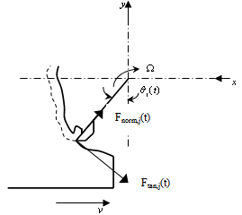
The tool is prescribed to cut a circular slot on a workpiece W along a circular path C of radius r at a tangential speed v as shown in figure1. The displacement due to revolutionary motion of the tool is referred to an inertial coordinate system  which is fixed at the initial position of the tool with
  pointing in the initial feed direction. The non-inertial reference coordinate system
  displaces in phase with the tool while rotating at a constant angular speed
 . The tool rotates with spindle speed
  given in revolutions per minute (rpm).
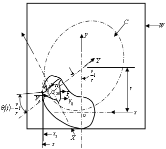 | Figure 1. Dynamical model of circular end-milling |
At any time t the motion of the tool in the instantaneous feed direction  is a linear superposition of prescribed feed motion and vibrations. The vibrations are composed of the tool’s response to force of tool-workpiece interaction that is devoid of self-excited vibrations
  and perturbations
  of the tool due regenerative effects. The displacement of the tool from y-axis at time t is
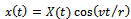 . This becomes
  | (1) |
It is seen from figure1 that the spring force and damping force are respectively given as  and
and  giving rise to the equation of motion in x direction becoming
 | (2) |
where  is the cutting force in x direction for jth tooth of the tool. The x-component of cutting force for jth tooth of the tool is seen from tool-workpiece disposition of figure2 to become
 | (3) |
Where  is a screen function that has the value of unity when the tool is active but varnishes when the tool is inactive (not cutting). If the start and end angles of cut are designated
  and
and  respectively
  becomes
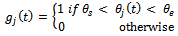 | (4) |
In this work, the instantaneous angular position of jth tooth  is measured clockwise relative to the negative
  axis. The motion of
  reference frame has the effect of extending the active time of cut such that screen function for circular slotting at time t becomes
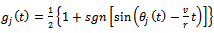 | (5) |
 | Figure 2. Milling tooth-workpiece disposition |
 is number of teeth on the milling tool meaning that j will have the values 1, 2, 3......
  . The teeth are numbered in line with rotational direction.
  is given by the equation
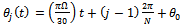 | (6) |
where  is the initial angular position of the tooth indexed 1. Total x-component of cutting force for the tool becomes
  | (7) |
The milling tangential and normal cutting forces for the jth tooth can be given by the non-linear laws [1] | (8) |
 | (9) |
where w is depth of cut, C is the cutting coefficient associated with the workpiece,  is the actual feed and
  is an exponent that is usually less than one having a value of
  for the three-quarter rule. is the ratio of normal cutting force coefficient to tangential cutting force coefficient.
  is used in this work to conform with literature[1]. The event of introducing equations (8) and (9) into (7) gives equation for x-component of cutting force.
 | (10) |
 is the difference between present and one period delayed position of tool, thus
 | (11) |
where  and
and  in figure1. Equations (10) and (11) taken together give
 | (12) |
With the designation , equation (12) becomes
 | (13) |
Equation (2) becomes | (14) |
Equation (14) becomes re-arranged  | (15) |
Based on the assumptions; the ratio  does not get too high, spindle speed
  does not get too low and time t lies in the interval[0,τ] the simplifications;
  and
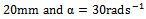
and  are admissible. Some attributes of a high-speed machining system are as follows[9]: spindles capable of speeds exceeding 40 thousand revolutions per minute while simultaneously delivering tens of kilowatts of power to the cutting zone, rigid low-mass machine-tool structures, high-speed linear slide-ways capable of coordinated linear motions at tangential speeds of up to 0.6 meters per second and accelerations of 20 meters per second squared. If for illustration it is assumed that a circular slot of radius
  is created by a three tooth end-miller at very high feed speed
  , spindle speed
  and
and  seconds then
 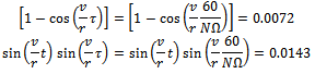 These results are seen to be close to the simplifications even at low
  and high feed. Since feed speeds in circular cut is expected to be much smaller than
 , the simplifications are expected to be met for real circular milling process even when the radius gets smaller. This expectation is higher at higher spindle speeds. In light of equation (1) the actual feed
  is re-written on the basis of the simplifications to become
 | (16) |
The linearized Taylor series expansion of  about
about  is
is | (17) |
Inserting equations (1), (17) and  into equation (15) gives
 | (18) |
Equation (18) governs the motion of the unperturbed tool. Equation (18) is used to eliminate the  component of motion in equation (15) to give the perturbation model
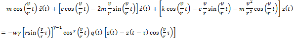 | (19) |
The specific force variation of circular end-milling is seen from the right-hand side of (19) to have the form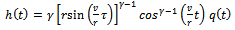 | (20) |
Making use of the relations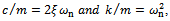 equation (19) by virtue of equation (20) becomes
 | (21) |
Equation (21) is a non-periodic DDE. But can be simplified to be periodic.Firstly, when radius of curvature r approaches infinity the end-milling process of figure1 approaches straight line milling operation. Under this condition equations (20) and (21) respectively approach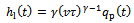 | (22) |
 | (23) |
Another τ-periodic simplification of equation (21) results when the approximation  is made leading to equations (20) and (21) respectively becoming
 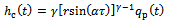 | (24) |
 | (25) |
where  is termed angular feed speed.
  is measured in radians per second. Equation (25) is the resulting dynamical model of circular end-milling. The effect of curvature is reflected by the presence of
  in both equations (24) and (25). This equation could also be viewed as corrected form of equation (23) for application to the case of circular end-milling. The τ-periodicity of equations (23) and (25) means amenability of stability analysis to the extended Floquet theory for delayed systems. For the same tool-workpiece combination, the periodic circular end- milling with tangential feed speed
  is considered equivalent to straight-line end-milling with linear feed speed
  when
when . This forms the basis of comparison of equations (23) and (25).The first direct comparison of circular end-milling and straight-line end-milling lies in comparing
  and
and  on same time axis as shown in figure3 (a) for
 and figure3 (b) for
 . The plot of specific force variations
  and
and  is seen in figure3 for a system with the typical specification;
 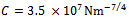 ,
,  (from the three-quarter rule),
  to exhibit τ-periodicity. It is noteworthy that the graphical forms of
  and
and  are identical for three tooth end-miller at the parameters chosen. This is expected from the fact that coefficient of
  in (22) and (24) are similar at reasonably high
  and low
 .
. | Figure 3. Specific force variation of periodic circular end-milling at  and (a) and (a)  (b) (b)  compared with that of equivalent linear feed end-milling compared with that of equivalent linear feed end-milling |
Though not presented equality between  and
and  is also seen for other end-millers of different number of teeth. Equations (23) and (25) have identical coefficient of perturbation velocity while their coefficient of perturbation displacement are almost equal when
  is not too big. This means that stability of equations (23) and (25) are thus expected to be identical.
3. Modified Full-Discretization Map for Circular Milling
The map of full-discretization generated in [7] and illustrated also in[7] to be more compact, faster and more convergent than the older full discretization map given in[8] is as follows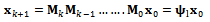 | (26) |
where 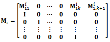 and
and 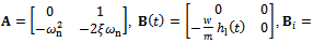
 ,
, 
 ,
,  and
and 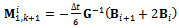 . The approximate monodromy
  acts as a second order tensor that transforms the delayed state
  to the present state
 . Equation (26) is called modified full-discretization map (MFDM) in[7].The basic idea and procedure of full-discretization method used in[7] to generate (26) for linear feed end-milling is adopted here in the model transformation of the periodic DDE model for circular end-milling. Equation (25) is first denoted in state space as
 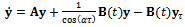 | (27) |
where  and
and . The discrete delay τ of the system is divided into k equal time intervals
  where
where  and
and
 The discretization integer k is the approximation parameter. Equation (27) is approximated in each of the discrete intervals as
  | (28) |
The time-dependent matrices and vectors are approximated linear with t as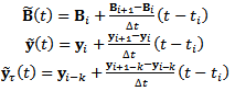 | (29) |
in each of the intervals .Direct integration of equation (28) in the discrete interval
 making use of the result
 leads to
 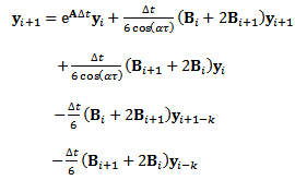 | (30) |
Equation (30) becomes re-arranged to become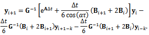 | (31) |
where 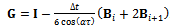 . This is put in matrix form to give
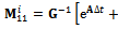
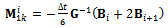
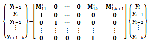 | (32) |
where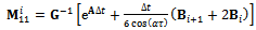 ,
, 
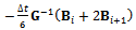 and
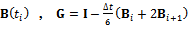
and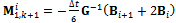 . If equation (32) is designated as
  the MFDM for the system becomes
 | (33) |
The finite Floquet transition matrix in this case becomes  | (34) |
The approximate monodromy operator  maps the delayed state
  to the present state
 . The basic idea of stability analysis is that all the eigenvalues of a monodromy operator must be of magnitude less than one for asymptotic stability. Stability transition curve is then tracked along parameter combinations of neutral stability. Neutral stability means unit moduli for maximum magnitude (critical) eigenvalues. These critical eigenvalues are analytical[10] and experimentally[11] established for milling process to be either -1 (in the case of flip or period two bifurcation) or a complex conjugate pair ( in the case of secondary Hopf or Neimark-sacker bifurcation).
4. Results and Discussions
The stability charts of figures 4 and 5 are calculated by a MATLAB program that is executed by the contour command. The parameters utilized are 
 and
and . Calculation of eigen-values of
  and
and  with
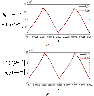
with  is done on a 200 by 25 data grid with spindle speed steps 96rpm and depth of cut steps 0.0008m. The points at which critical conditions occur are connected by the stability transition curve. Stability charts of three and ten tooth end-millers are generated in figures 4 and 5 respectively. Each circular end-milling tool is slotting along circular feed paths of radius
  and angular feed speed of
 , 10 or 30
 while the equivalent straight-line (or linear) end-miller is prescribed with feed speed of
 or
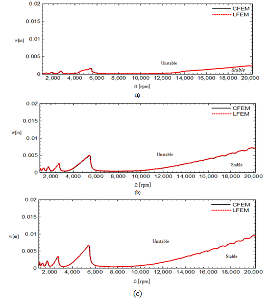
or . Results of stability analysis of both periodic circular and straight-line end-milling of equal feed speed are placed on the same axis for direct comparison of chatter stability. Points below the curve are stable while points above it are unstable. Stability charts at all feed speeds are produced with same scale for comparison of chatter stability of tools of different number of teeth and different feed speed. It is seen from figures 4 and 5 that circular feed end-milling (CFEM) and linear feed end-milling (LFEM) have coincident stability transition curves. This result is expected since there is no curvature effect (either r or
 ) seen in the coefficient of perturbation velocity of the proposed periodic model (equation (25)) for circular end-milling. This result justifies any earlier approximation of circular end-milling with the classical model for linear feed end-milling. It should be noted that chatter stability improves with increase of
  for circular end-milling or increase in v for linear feed end-milling.
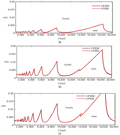 | Figure 4. Stability chart for three tooth end-miller (a)  and and  (b) (b)  and and  (c) (c)  and and  The full black line is for CFEM while the red dotted line is for LFEM The full black line is for CFEM while the red dotted line is for LFEM |
 | Figure 5. Stability chart for ten tooth end-miller (a)  and and  (b) (b)  and and  (c) (c)  and and  The full black line is for CFEM while the red dotted line is for LFEM The full black line is for CFEM while the red dotted line is for LFEM |
5. Conclusions
Model described by non-periodic delay differential equation is presented for circular end-milling. A simplification of this model gives an approximate periodic delay differential for circular end-milling. Another simplification of the non-periodic model based on the fact that straight-line feed end-milling is a circular end-milling of infinitely large radius led to the traditional periodic delay differential equation seen in literature for linear feed end-milling. A modified full-discretization mapping is used in regenerative chatter stability comparison of the periodic circular end-milling and linear feed end-milling. It is derived that circular end-milling is as stable as its linear feed equivalent. Though this result has been implied in some earlier practice of approximating circular feed end-milling with the mathematical model of its linear feed equivalent, this work provides theoretical justification to that. Equivalence is based on equal feed speed. Increase in angular feed speed causes improvement in chatter stability of circular end-milling while increase in linear feed speed equivalently causes improvement in chatter stability of straight-line feed end-milling.
References
| [1] | T. Insperger, Stability Analysis of Periodic Delay- Differential Equations Modelling Machine Tool Chatter: PhD dissertation, Budapest University of Technology and Economics (2002). |
| [2] | R.P.H. Faassen, N. van de Wouw, J.A.J. Oosterling, H. Nijmeijer, Prediction of regenerative chatter by modelling and analysis of high-speed milling, International Journal of Machine Tools & Manufacture 43 (2003) 1437–1446. |
| [3] | T. Insperger, B.P. Mann, G. Stepan, P.V. Bayly, Stability of up-milling and down-milling, part 1: alternative analytical methods, International Journal of Machine Tools and Manufacture 43 (2003) 25–34. |
| [4] | F. Hartung, T. Insperger, G. Ste´pa´n, J. Turi, Approximate stability charts for milling processes using semi-discretization, Applied Mathematics and Computation, 174 (2006) 51–73. |
| [5] | O. A. Bobrenkov, F. A. Khasawneh, E. A. Butcher, B. P. Mann, Analysis of milling dynamics for simultaneously engaged cutting teeth, Journal of Sound and Vibration, 329 (2010) 585–606. |
| [6] | C. G. Ozoegwu, Chatter of Plastic Milling CNC Machine: Master of Engineering thesis, Nnamdi Azikiwe University Awka (2011). |
| [7] | C. G. Ozoegwu, Faster and more convergent full- discretization map for chatter stability analysis of end-milling, Machining Science and Technology, submitted. |
| [8] | T. Insperger, Full-discretization and semi-discretization for milling stability prediction: Some comments, International Journal of Machine Tools and Manufacture 50 (2010) 658–662. |
| [9] | M.A. Davies, T. J. Burns, T. L. Schmitz, High-Speed Machining Processes: Dynamics of Multiple Scales, National Institute of Standards and Technology, 100 Bureau Drive, Gaithersburg MD 20899, USA, (1999). |
| [10] | T. Insperger, G. Stepan, Stability of High-Speed Milling, Proceedings of Symposium on Nonlinear Dynamics and Stochastic Mechanics, Orlando, Florida AMD-241 (2000) pp.119-123. |
| [11] | M. A. Davies, J. R. Pratt, B. Dutterer, T. J. Burns, Stability prediction for low radial immersion milling, Journal of Manufacturing Science and Engineering 124 (2002) 217-225. |
 Abstract
 Reference
 Full-Text PDF
 Full-text HTML