-
Paper Information
- Next Paper
- Previous Paper
- Paper Submission
-
Journal Information
- About This Journal
- Editorial Board
- Current Issue
- Archive
- Author Guidelines
- Contact Us
Science and Technology
p-ISSN: 2163-2669 e-ISSN: 2163-2677
2012; 2(6): 191-197
doi: 10.5923/j.scit.20120206.08
Investigation of Beam Performance Parameters in a Pierce-Type Electron Gun
 Abstract
 Reference
 Full-Text PDF
 Full-Text HTML
Ashraf A. El-Saftawy 1, Ahmed Elfalaky 2, Magdi S. Ragheb 1, Safwat G. Zakhary 1
1Accelerators and Ion Sources Department, Nuclear Research Center, Atomic Energy Authority, Cairo, P.O. 13759, Egypt
2Physics Department, Faculty of Science,Zagazig University, Zagazig, P.O. 44519, Egypt
Correspondence to: Ashraf A. El-Saftawy , Accelerators and Ion Sources Department, Nuclear Research Center, Atomic Energy Authority, Cairo, P.O. 13759, Egypt.
| Email: |  |
Copyright © 2012 Scientific & Academic Publishing. All Rights Reserved.
In the present work, an investigation has been made for the extraction characteristics and beam diagnosis for a Pierce-type electron gun with spherical anode to acquire an electron beam suitable for different applications. The acceleration voltage increases the electron beam currents up to 250 mA at Acceleration voltage 75kV and decreases the beam perveance, beam waist and beam emittance. The minimum beam radius could be found at the minimum beam perveance and maximum convergence angle. Also the increase of the accelerating voltage affects the increase of the beam fluence rate up to 1.3 x 10¹⁸ e/min.cm2, due to the increase of the extracted current. Tracing the electron beam profile by X-Y probe scanner along the beam line at two different places reveals that the spherical anode affects the beam to be convergent. The electron beam could be suited for the two suggested experiments in our lab, plasma acceleration and surface modifications of polymers.
Keywords: Electron Gun, Beam Geometry, Perveance, Emittance
Cite this paper: Ashraf A. El-Saftawy , Ahmed Elfalaky , Magdi S. Ragheb , Safwat G. Zakhary , "Investigation of Beam Performance Parameters in a Pierce-Type Electron Gun", Science and Technology, Vol. 2 No. 6, 2012, pp. 191-197. doi: 10.5923/j.scit.20120206.08.
Article Outline
1. Introduction
- The development of electron beam devices has a long history and electron beam technology has undergone several changes over the years. A variety of electron beam sources have been designed and utilized in the basic research as well as for the industrial applications[1-3]. The electron beam parameters such as diameter, current, energy, etc. were adjusted to suit their specific experimental requirements[4]. Charged particle beams from different types of sources have to be transmitted without loss of the particles through the accelerator. It is very important that the particles strike the target should have the parameters required for a certain application. For a beam transmission without loss of the particles, the cross-section of the beam must not exceed a given maximum value of a well-defined point. To achieve this we will introduce an important quantity known as emittance which one wants to minimize for any given current[5]. The emittance is an important aspect for high-quality beam, which is basically defined by the product of the width and transverse velocity spread of the beam (region of phase space occupied by beam). If the beam is densely packed, then the emittance is said to low. Whereas beam that is somewhat spread out has high emittance[6-8]. Knowing the beam properties before its injection into the accelerator saves the time needed for accelerator tuning and increases the overall efficiency of the beam transmission[9]. At the present work, the electron beam properties will be defined and regulated to match the suggested applications (plasma Acceleration and electron beam treatments of different types of materials). The electron beam diagnostics done in this work include the measurement of electron beam intensity, perveance, profile, and hence emittance as a function the acceleration voltages. The beam fluence and fluence rate will also be considered.
2. Experimental Setup
- The electron beam is produced from a Pierce-type electron gun (figure 1) with an indirectly heated cathode operating in a diode circuit. The Pierce electrode makes an angle 67.5o with the beam edge. The cathode, together with the beam shaping electrode, is connected to a pulse modulator which provides negative high voltage (up to 80 kV) pulses with variable pulse repetition rates (from 31.25 to 500 counts/s) which accelerates the electrons with a velocity of about 0.5c (the velocity of light). The anode with a spherical shape is grounded to the vacuum chamber i.e. considered positive with respect to the cathode and the beam shaping electrodes.In the field free region behind the anode, a chamber exists having three flanges, figure 1. The gun section is connected to the field free space chamber through an aperture in the anode electrode. The electron beam scanner, shown in figure 2, is an electromechanical system with a thin long wire (0.1mm diameter and 100mm long) is used for probing the beam to study the dependence of beam parameters on the acceleration voltages.
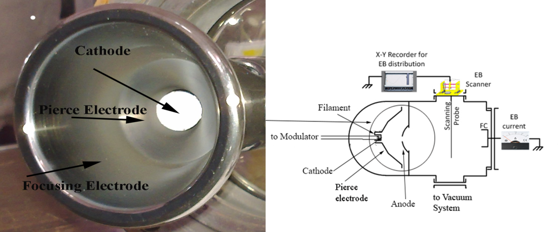 | Figure 1. Electron gun configuration |
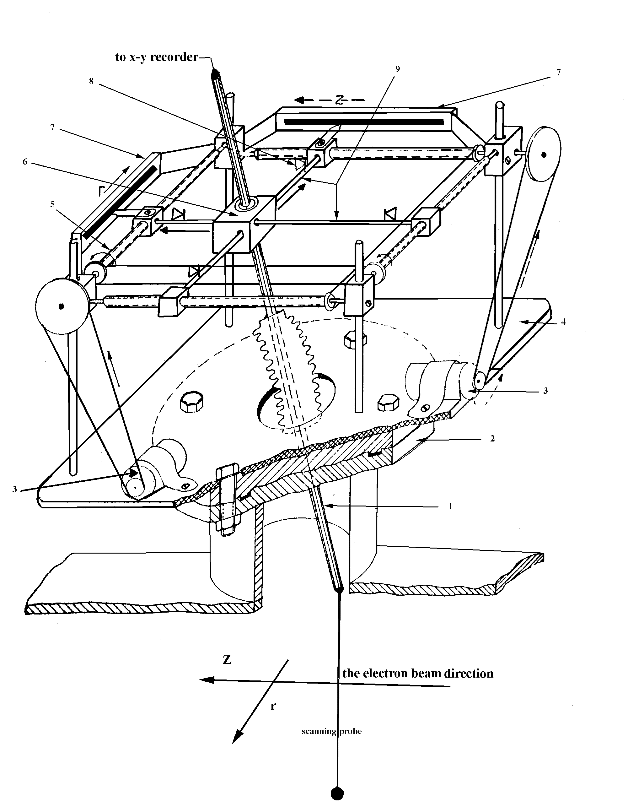 | Figure 2. Electron beam scanner (1- Coaxial insulated rod.2-The upper middle flange of the field free region.3-Motors.4- Metallic square sheet. 5- Screw rods.6- Central cuboid.7-Sliding resistance. 8- Micro-switch. 9- Two perpendicular cylindrical rods |
3. Results and Discussion
3.1. Studying Electron Beam Intensity and Perveance
- Figure 3 shows the influence of the Acceleration voltages on the extracted electron beam current and perveance. The electron beam current increases (from 20mA up to 250mA) with the increase of the Acceleration voltage up to 75kV, this dependency is in close agreement with child-Langmuir[11]:
 | (1) |
 down to 1.2 x 10⁻²
 and the Acceleration voltages increase from 5kV up to 75kV respectively. For values of the perveance P ≤ 10-2
 the intrinsic electric field of the beam has an appreciable effect on the motions of the electrons. But for values of P ≥ 104
 , the effect of space charge can be neglected[15].
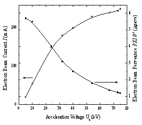 | Figure 3. Electron beam current and perveance as a function of acceleration voltage |
3.2. Electron Beam Profile and Emittance Analysis
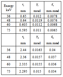
- Here we will trace the beam profile which describes the current intensity distribution, the beam width, and the angular divergence of the beam. For plasma acceleration experiment, the injected electron beam has to be very thin, with high convergence angle and very low emittance. These conditions are achieved at the electron beam waist which is located at a distance 20 mm from the anode aperture. So that, the electron beam profile is traced at this point to find the optimum conditions for performing the plasma acceleration experiments. The traced profile (at acceleration voltages 36kV, 48kV, 60kV and 75kV) is shown in figure 4a which is fitted to the Gaussian function, and the fitting parameters are shown in table 1.
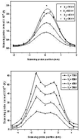 | Figure 4. Electron beam profile traced at a) 20mm and b) 150mm from the anode aperture |
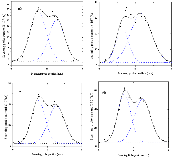 | Figure 5. Gaussian fit for beam profile traced at 150mm for different acceleration voltages; a) 36kV, b) 48kV, c) 60kV and d) 75kV., Where( ____ )is the cumulative fit peak, (-----) is the fit peak 1 and 2, and (……) is the base line |
 | (2) |
 | (3) |
 | (4) |
 | (5) |
 is given by:
  | (6) |
 is an upright ellipse with extreme values (
 ); then its area is
 , so:
, so: | (7) |
 , Where; r is the beam radius and z is the distance from the exit aperture of the beam to the scanning probe. The increase of the acceleration voltage decreases the width and the divergence angle of the electron beam and hence the electron beam emittance decreases. Table (2) confirms the principle which states that theminimum beam radius is found at minimum beam perveance and higher beam convergence.
 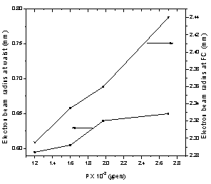 | Figure 6. Beam radius at waist and Faraday cup variation with beam perveance |
|
 are the beam radius, convergence angle and emittance at waist, and
  are the beam radius, convergence angle and emittance at the entrance of FC.
3.3. Electron Beam Fluence Calculation
- Electron beam absorbed dose is used to identify the electron beam radiation in the science of dosimetry. Also the following quantities are used to describe an ionizing radiation beam (electron beam): particle fluence, energy fluence, particle fluence rate and energy fluence rate. These quantities are usually used to describe charged particle beam[22, 23]. In this work we will use the terms, electron beam fluence and fluence rate to describe the electron beam in the irradiation of materials surfaces experiments. According to the definitions of fluence and fluence rate, these parameters are calculated and shown in figures 7 and 8. The particle fluence
 (measured in m-2) is defined as the number of particles dN incident on cross-sectional area dAand could be expressed as in the formula;
  , While the particle fluence rate
  (measured in m-2s-1) is the increment of the fluence d∅ in time interval dt and could be expressed as
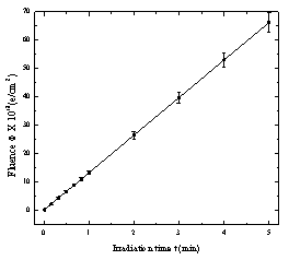
  .Figure 7 shows the increase of the fluence rate (number of electrons incident on a specific area per second) with the increase of the acceleration voltage. The maximum number of electrons enter the FC are 1.56 X 10¹⁸ electrons at acceleration voltage 75 kV. The fluence rate is in the range from (2 x 10¹⁶ up to 2.21 x 10¹⁷) electrons/s.cm2 at energies between 5keV and 75keV respectively.According to the irradiation time the electron beam fluence is calibrated at electron beam energy 75keV. Figure 8 shows a straight line, its slope (1.3 x 10¹⁸ e/min.cm2) represents the electron beam fluence rate.
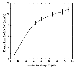 | Figure 7. Fluence rate as a function of acceleration voltage |
 | Figure 8. Calibration of electron beam fluence at 75keV |
4. Conclusions
- Different types of electron guns have been designed for producing different electron beam energies. In this work, a Pierce-type electron gun with spherical anode has been investigated to produce an electron beam with suitable properties valid for the suggested application in our laboratory. Upon investigation of the designed gun, it has been found that the acceleration voltage increases the electron beam currents up to 250mA and decreases the beam perveance. The spherical extraction electrode (anode) is believed to produce a convergent beam. This effect is proved by tracing the electron beam density distribution at two different places along the beam line. Also it is found that the distribution of the electron beam affected by the acceleration voltage i.e. the electron beam diameter increases with the decrease of the acceleration voltage. So that the higher the acceleration voltage, the lower the beam emittance. Electron beam emittance is preferably to be as low as possible for the suggested plasma acceleration experiment. While the polymer treatment experiment requires a spread out beam with larger diameter i.e. with high emittance. It is proven that the minimum beam radius could be found at the minimum beam perveance and maximum convergence angle. Also the electron beam fluence rate and electron fluence are considered and calculated, these two values depend on the acceleration voltage. We can conclude that the resulting electron beam (density and shape) could be controlled by not only the gun geometry but also the acceleration voltages to produce a suitable electron beam for different applications.
References
| [1] | R. Bakish, “Electron Beam Technology”, Wiley, New York, 1962. |
| [2] | A.V. Deore, B.J. Patil, V.N. Bhoraskar, S.D. Dhole, “Design, Development and Characterization of Tetrode Type Electron Gun System for Generation of Low energy Electrons”, Indian Journal of Pure & Applied Physics, Vol. 50, 482-485, 2012. |
| [3] | R. Mehnert, “Review of Industrial Applications of Electron Accelerators”, Nucl. Instr. and Meth. B 113, 81-87, 1996. |
| [4] | S.K. Mahapatra, S.D. Dhole and V.N. Bhoraskar, “A 20 keV Electron Gun System for the Electron Irradiation Experiment”, Nucl. Instr. and Meth in Phys. Res. A 536, 222-225, 2005. |
| [5] | S. Humphries Jr., “Charged Particle Beams”, Wiley, New York, 1990 |
| [6] | M. Reiser, “Theory & Design of Charged Particle Beams”, Wiley”, New York, 1994. |
| [7] | G. Herrmann, “Optical Theory of Thermal Velocity Effects in Cylindrical Electron Beams”, J. Appl. Phys. 29 (2), 127, 1958. |
| [8] | K. Masood, M. Iqbal and M. Zakaullah, “Emission Characteristics of the Thermionic Electron Beam Sources Developed at EBSDL”, Nucl. Instr. and Meth in Phys. Res. A 584, 9, 2008. |
| [9] | M.S. Ragheb and M.H.S. Bakr, “Improvement of Auger Spectra Using A.C. Modulation Technique”, Radiat. Phys. Chem. 47 (5), 673-675, 1996. |
| [10] | M.H.S. Bakr and M.S. Ragheb, “the Electron Injector IV. A Remote Tracer for the Electron Beam Current”, Arab Republic of Egypt, Atomic Energy Establishment (AREAEE) / Rep. 262, 1-16, 1981. |
| [11] | S.I. Molokovsky and A.D. Sushkov, “Intense Electron and Ion Beams”, Springer-Verlag, Berlin, 2005. |
| [12] | A.M.D. Assa’d and M.M. El-Gomati, “Backscattered Coefficients for Low Energy Electrons”, Scanning Microscopy Vol. 12, No. 1, 185 – 192, 1998. |
| [13] | R.K. Yadav and R. Shanker, “Contribution of Backscattered Electrons to the Total Electron Yield Produced in Collisions of 8-28 keV Electrons with Tungsten”, PRAMANA J. of Physics, Vol. 68, No 3, 507-515, 2007. |
| [14] | A.A. El-Saftawy, A.A. Hassan, M.M. Abdelbaki, S.G. Zakhary and Z. Awaad, “Enhancement of Axial Type RF Source Characteristics”, Arab J. Nucl. Sci. Appl., 39 (2), 189-197, 2006. |
| [15] | A. Zhigarev; “Electron Optics and Electron Beam Devices”, Mir Publisher, Moscow, 1975. |
| [16] | P. Tippler, “Physics for Scientists and Engineers: Electricity, Magnetism, Light, and Elementary Modern Physics”, (5th ed.). W. H. Freeman, 2004. |
| [17] | M.E. Abdelaziz, S.G. Zakhary and M.S. Ragheb, “Beam diagnostics extracted from radio frequency driven ion source”, Rev. Sci. Instrum. 71,2, 1137-1139, 2000. |
| [18] | S.G. Zakhary, “Beam Diagnostic Technique for a Small-Size High-Efficiency Radio-Frequency Ion Source”, Rev. Sci. Instrum. 66, 12, 1995. |
| [19] | A.A. El-Saftawy, “Factors Enhancing the Ion Beam Optics and Transport in the Low Energy Accelerator (50keV)”, M.Sc. Thesis, Faculty of Science, Zagazig University, 2007. |
| [20] | T.S. Green, “Beam Formation and Space Charge Neutralization”, IEEE Trans. Nucl.Sci. 23 (2), 918-928, 1976. |
| [21] | A. Hassan, A. Elsaftawy and S.G. Zakhary, “Analytical Studies of the Plasma Extraction Electrodes and Ion Beam Formation”, Nucl. Instr. and Meth. in Phys. Res. A 586, 148-152, 2008. |
| [22] | B. Nilsson, A. Montelius and P. Andreo, “Determination of fluence correction factors in electron beam dosimetry”, Radiother. Oncol. 37, 1995. |
| [23] | D.T. Burns, G.X. Ding and D.W.O. Rogers,” R50 as a Beam Quality Specifier for Selecting Stopping Power Ratios and Reference Depths for Electron Dosimetry”, Med. Phys. 2, 383–388, 1996. |