-
Paper Information
- Previous Paper
- Paper Submission
-
Journal Information
- About This Journal
- Editorial Board
- Current Issue
- Archive
- Author Guidelines
- Contact Us
Science and Technology
p-ISSN: 2163-2669 e-ISSN: 2163-2677
2012; 2(4): 98-108
doi: 10.5923/j.scit.20120204.07
Factors Enhancing Production of Multicharged Ion Sources and Their Applications
 Abstract
 Reference
 Full-Text PDF
 Full-Text HTML
M.M. Abdelrahman
Accelerators & Ion Sources Department, Nuclear Research Center, Atomic Energy Authority P.O. Box: 13759Inchas, Atomic Energy, Cairo, Egypt
Correspondence to: M.M. Abdelrahman , Accelerators & Ion Sources Department, Nuclear Research Center, Atomic Energy Authority P.O. Box: 13759Inchas, Atomic Energy, Cairo, Egypt.
| Email: |  |
Copyright © 2012 Scientific & Academic Publishing. All Rights Reserved.
In this article, Principle of plasma generation is discussed and investigated. In all types of ion sources, ions are produced by various types of gas discharge including electron collisions with gas particles. The general parameters are a source of electrons, a small region of relatively high gas pressure, an electric field to accelerate the electrons in order to produce an intense gas discharge (plasma) with a relatively high electron and ions density and some mechanism for extracting a collimated parallel high current ion beam. Our research work was quickly described, reviewed and gave some results showing the importance in some areas of applications. A short historical review on basics and applications of some multicharged ion sources is presented. The multicharged ion source is evaluated by; the large ion current extracted from it, the large percentage of ions in the beam, the higher degree of ionization inside the atom, the small gas consumptions, and the degree of divergence of the extracted ions must be small.
Keywords: Multicharged Ions, ECR Ion Sources, Laser Ion Sources, PIG sources
Article Outline
1. Introduction
- Ion sources are used in many research fields as mass separation, ion implantation, atomic physics, fusion and a variety of accelerators for nuclear and particle physics with different requirements. The development of multicharged ion (MCI) sources received a strong push from heavy ion accelerator centers, due to the fact that the energy range of a heavy ion accelerator is strongly increased by the charge state of the injected ions. Moreover, the multicharged ion sources are useful for basic investigations in atomic physics, surface physics and related areas.The more demanding the applications, the more the ion source has to be carefully designed and optimised to get optimum performance. High performance of ion sources represents in having ionization efficiency, maximum current, high charge state, size and cost with taking into account the limits of power and the radiation environment. Ion sources are devices for producing and delivering ion beams that may be directly used from the source or after acceleration by a simple or complex accelerator structure. Ion sources may be classified according to the ion characteristics in sources of positive ions and sources of negative ions. Positive ions are produced in most ion sources by electron-atom and electron-ion collisions in a plasma containing neutral particles, ions and electrons. In the most common positive ion sources, electrons are produced by a hot filament and the plasma is created by an electric arc discharge with low gas pressure. Multicharged ion sources have emerged with the existence of accelerators, when multicharged ions of carbon were observed by Alvarez at the 37–inch cyclotron in 19401. There are many types of multicharged ion sources for use in heavy ion accelerators and atomic physics experiments, e.g., PIG ion sources, Duoplasmatron-and Duopigatron ion sources2. PIG ion sources have found widespread application in injectors of large particle accelerators used for nuclear and high–energy physics research3. Multicharged ions were also produced by Duoplasmatron-and Duopigatron ion sources4 for applications in accelerators, ion implantation, sputter deposition and ion beam analysis. A new line for production and acceleration of multicharged ion beams was initiated by electron cyclotron resonance ion sources (ECRIS)5-7, electron beam ion sources (EBIS)8 and laser beam ion sources (LBIS)9. Electron cyclotron resonance ion sources are very reliable producers of multicharged ions and now used in many fields as atomic, nuclear and high energy physics; they are also useful for studies related to plasma physics10. Electron beam ion sources are useful for fundamental and applied areas of research in the physics of multicharged ions11, and for low energy collision experiments12. Laser beam ion sources have been used, e.g., for various applications as surface modification, very large scale integrated circuit fabrication, laser mass spectrometry and in medicine13. Nowadays, multicharged ions are relevant in studies on multiply excited species (hollow atom spectroscopy), plasma chemistry and technology, semiconductor industry, information technology and thermonuclear fusion reactor development14, X–ray astronomy, solar physics, microelectronics and nanotechnology, ion implantation, ion lithography and medicine15.
2. Criteria for Production of Multicharged Ion Beams
- Production of intense beams of multicharged ions is difficult since suitable conditions for effective ionization and minimum losses of highly charged ions have to be realized. The primary mechanisms for production of multicharged ions are photo ionization and electron impact ionization. The electron impact ionization process is most generally used in the laboratory. Electron impact ionization can result in the removal of more than one electron from an atom or ion, provided that the bombarding electrons have sufficient energy. In order to produce multicharged ions, some criteria have to be fulfilled10:(1) The energy of the electrons should be higher than the ionization potential for reaching the desired charge state,(2) Ions should be confined for a time sufficient to reach the required charge state,(3) To minimize charge exchange the residual gas pressure should be kept as low as possible.
2.1. Ionization Processes
- Ionization is a process in which an atom loses one or more of its electrons to another atom. The process of ionization occurs in nature as a result of interactions of photons, electrons, or other atoms or ions with matter. Understanding this process and inelastic processes in atomic collisions in general is important for a wide range of pure and applied research fields such as astrophysics, plasma physics and thermonuclear fusion. Multicharged ions produced by electron impact ionization can be produced by one of the following processes: outer shell ionization (single ionization), and inner shell ionization with subsequent rearrangement processes (successive-single ionization). In multicharged ion sources, the maximum charge state that can be obtained is limited by the maximum incident electron energy. The impact of a free electron of high enough kinetic energy on an atom or an ion may result in the transfer of energy to a bound electron with more than the binding energy in the atom or ion; as a result this electron is transferred to the continuum of unbound states. In a single ionization event, the incident electron must have an energy equal to the sum of all ionization potentials of the removed electrons, whereas for successive-single ionization they require only the energy of each electron removed. In the case of single ionization, there are two main parameters that determine the process namely the electron temperature Te and the electron density ne. For successive-single ionization which is the main process for the production of multicharged ions. The probability of producing multicharged ions by single impact ionization falls off rapidly with increasing charge state of ions. Therefore, a more efficient method to obtain a reasonable yield of highly charged ions is by successive-single ionization. The loss of an electron from the atom A or the ion A+ is an ionization process that can be described as:
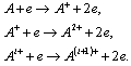 | (1) |
 | (2) |
 | (3) |
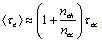
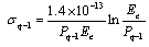
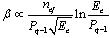
 the mean effective ion charge and Te the electron temperature.The ionization rate for an ion of charge state q is:
 | (4) |
 | (5) |
 | (6) |
 | (7) |
 | (8) |
2.2. Performance Parameters of Multicharged Ion Sources
- The development of ion sources was stimulated in the early times by the requirements of particle accelerators, mass spectrometers, neutron generators, etc. Nowadays the field of ion sources has grown into a wide variety of ion source subfields and has an essential impact on various high technology areas from material modification, isotope separation to nuclear fusion and ion propulsion. Each application of ion source requires a somewhat different form of source of certain performance characteristics. Different applications of ion sources require somewhat different sets of certain performance characteristics. Multicharged ion sources are characterized by the following parameters19:(1) The type of ion species that can be produced by the source(2) The ability of producing multicharged ions of different elements for their applications in particle accelerators, atomic physics, etc.(3) The extracted ion current which can be produced by the ion source,(4) The beam emittance of the ion source should be as low as possible,(5) Brightness; the brightness is inversely proportional to the beam emittance; a high value is desired,(6) The energy spread of the extracted beam from the source which depends on the ion source parameters as the magnetic field, gas pressure and RF power (in case of RF ion sources). Ion sources with low ion energy spread is preferred,(8) Ionization efficiency; this is the efficiency of the process by which the plasma is formed. A high efficiency allows high ion currents to be produced with relatively low gas flow,(9) There are a number of other parameters that are more or less important, depending on applications as the source lifetime, the source size, the power efficiency and the ease of maintenance.
3. Penning Ion Sources-(PIG)-MCIS
- The typical PIG-arrangement is shown in Fig. 1, for production of MCI, the discharge is typically operated in homogeneous magnetic field of some kG, at gas pressures between 10-4 Torr and some 10-1 Torr.
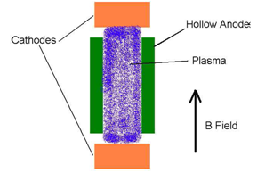 | Figure 1. PIG ion source |
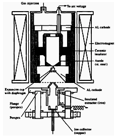 | Figure 2. Cold cathode Penning ion source 23 |
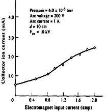 | Figure 3. influence of the magnetic field on the collector ion current23 |
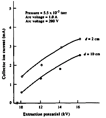 | Figure 4. Influence of the extraction potential On collector ion current at distance d = 2, 10 cm 23 |
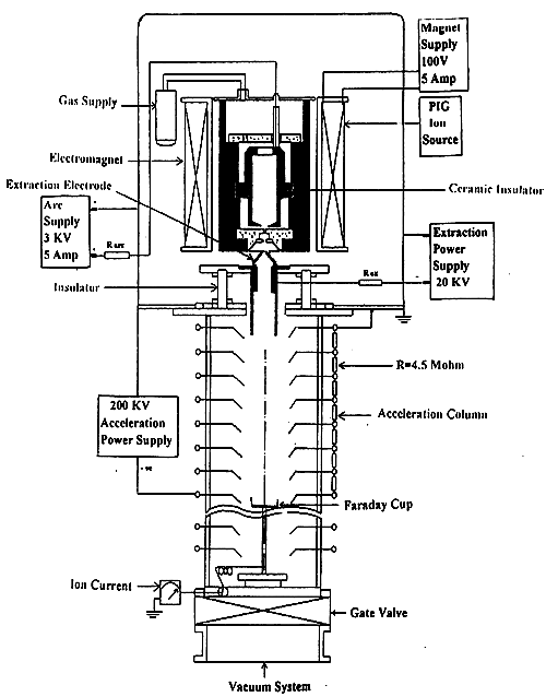 | Figure 5. Low energy accelerator with electrical circuit 24 |
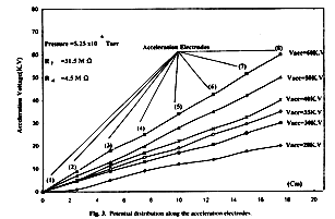 | Figure 6. Potential distribution along the acceleration electrodes24 |
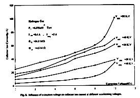 | Figure 7. Influence of extraction voltage on collector ion current at different accelerating voltages 24 |
4. Duoplasmatron and Duopigatron-MCIS
- The duoplasmatron ion source was developed by V. Ardenne24 as a powerful source for gas ions. The duoplasmatron ion source consists as shown in Fig. 8 of two plasma regions; the lower density plasma between the cathode and the intermediate electrode (IE) and the high density plasma between the IE and the anode.
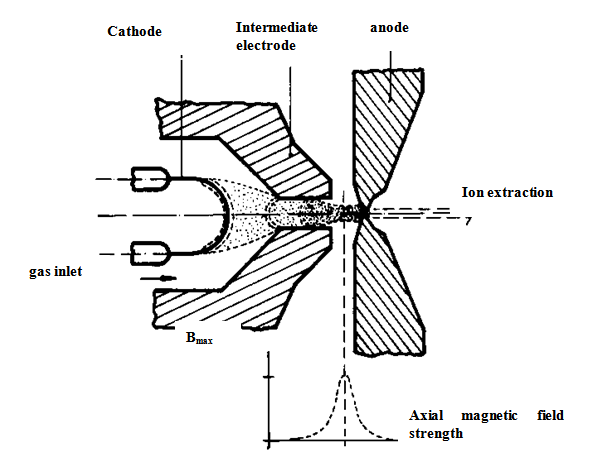 | Figure 8. Main elements of duoplasmatron ion source |
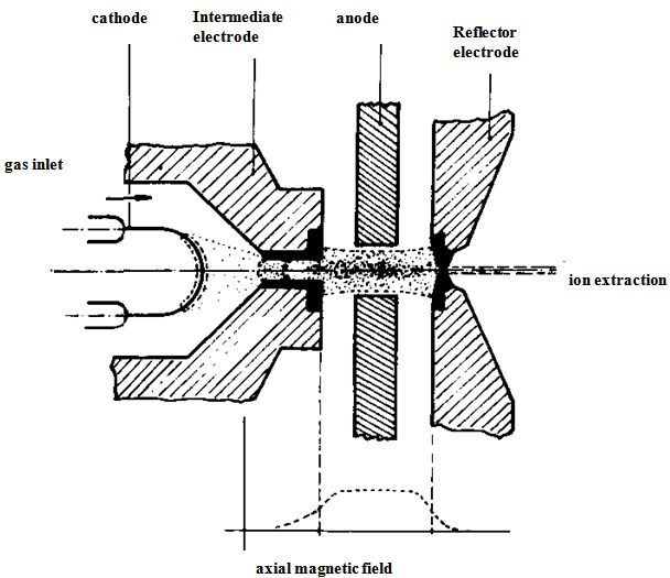 | Figure 9. Main elements of duopigatron ion source |
5. Electron Cyclotron Resonance Ion Sources (ECRIS)
- The properties of an ECRIS for delivering intense beams of multicharged ions depend on the microwave frequency that determines the electron density ne and electron temperature Te, and on the product (neτi). The product (neτi) may be increased by improving the plasma confinement (strong magnetic fields) and by techniques that add cold electrons to the plasma. An additional important condition for obtaining multicharged ions is a low background gas pressure (10-7 – 10-8 Torr) in the plasma chamber. In the ion beam line, charge exchange recombination processes should be avoided. In this subsection, a short historical review on basics and applications of ECR multicharged ion sources are described.
5.1. Basics of Multicharged ECR Ion Sources
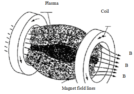
- The main parts of an ECR ion source are shown in Fig. 10.There is a vacuum plasma chamber (plasma tube), a gas feeding system, minimum-B-field configuration (combination of solenoid magnets and hexapole permanent magnet), and the microwave system. A set of solenoid magnets either permanent magnets or solenoids produces an axial magnetic mirror field inside the plasma chamber. The necessary radial field gradient is generated by a multipole permanent magnet (usually NdFeB).
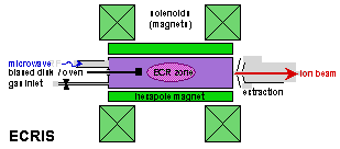 | Figure 10. Main elements of ECR ion source |
 | (9) |
5.2. RF Coupling and Ionization Efficiency
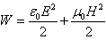
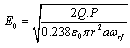
- In the ECRIS, the electrons are delivered by plasma and not by a cathode; they are accelerated by electromagnetic waves at the frequency of the electron cyclotron resonance. The electromagnetic waves can be introduced into the plasma chamber (plasma tube) through coaxial lines, antennas, loops and vacuum-tight dielectric windows. The choice depends on the frequency and the desired electromagnetic field pattern. Proper coupling of the RF power into the plasma in the ECR ion source is the most important factor in achieving high performance. Poor coupling of RF power to the plasma can result in undesirable effects as high reflected power, low plasma density, unstable operation and poor performance. The production of multicharged ions in an ECR ion source requires high microwave power to increase the plasma density, and low background gas pressure to reduce the charge exchange between ions and neutral particles. Once high microwave power is launched from the waveguide, it propagates into the plasma. An ECR zone is created when the magnetic field and the RF fields are superimposed and the electron cyclotron resonant frequency ωce equals the resonant frequency ωrf of the RF applied. In this ECR zone, a component of the electrical RF fields is perpendicular to the magnetic field and electrons crossing the zone are accelerated in circular orbits. During their acceleration, they collide with gas atoms. If these collisions allow electrons to reach energies above the ionization energy of the gas atoms, then the ECR plasma is ignited. The most efficient way for heating the plasma in an ECR ion source is by injecting right-hand circularly polarized waves along the direction of the magnetic field. The electric field vector for a right-hand circularly polarized wave rotates clockwise in time along the direction of magnetic field and has a resonance at the electron cyclotron frequency ωce which equals the resonant frequency ωrf of the RF applied. The direction of rotation for the plane of polarization for the right-hand circularly polarized wave is the same as the direction of gyration of the electrons. The electromagnetic wave looses energy by continuous acceleration of electrons and is therefore damped. The left-hand circularly polarized waves do not have a resonance with the electrons because they rotate in the opposite direction of the electron gyration.The relation between the electromagnetic fields and the input power derived for a cylindrical cavity is given by28:
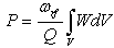 | (10) |
 | (11) |
 | (12) |
 | (13) |
 | (14) |
 | (15) |
 | (16) |
5.3. Minimum–B-field
- An important feature of ECR ion sources is their magnetic field structure. This structure is made up by the superposition of an axial field produced by a set of solenoid coils or permanent magnets and a radial field produced by a permanent magnetic multipole. Most ECRIS use minimum-B-field geometry. In this magnetic field structure, the ECR condition is fulfilled in the valley between the peaks of the magnetic field formed by the two solenoid coils. This form of magnetic structure does not stably confine the plasma if the magnetic field decreases in the radial direction. In order to secure a stable confinement, a multipole fields (octopoles, hexapoles and quadrupoles), have to be added (Fig.11).Such multipole fields provide radial confinement since they increase with distance from the axis. This magnetic confinement structure is called minimum–B-structure, where the magnetic field is the smallest in the center and increases in every direction from this center. Such magnetic multimirrors not only affect the ionization efficiency and thus the gas consumption, but also the ion lifetime. The better the confinement, the higher are the efficiencies of ionization and of production for highly charged ions. Usually, hexapole magnets are applied in ECRIS, because a higher order multipole has a larger loss surfaces at both ends usable for the ion extraction. On the other hand, the loss area of the quadrupole is just a line at the end which is not suitable for effective ion extraction. The region of higher magnetic field strength of an octopole is closer to the tube wall than that of a hexapole magnet. The magnetic mirror structure for minimum-B–configuration is principally characterized by the loss cone and the plasma pressure. The ratio of the maximum magnetic field strength at the magnetic throats to the magnetic field strength at the center is called the mirror ratio (
 ).
).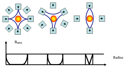 | Figure 11(a). Loss surfaces of different multipoles: octoples, hexapoles and quadrupoles and corresponding radial fields Bradial29 |
 | Figure 11(b). Magnetic mirror structure29 |
5.4. Applications of Multicharged ECR Ion Sources
- Electron cyclotron resonance ion sources (ECRIS) can produce singly charged and multicharged ions. Singly charged ECR ion sources have significant commercial applications. The performance of ECRIS has been continuously increased since their introduction by raising the magnetic field and the frequency of the RF generators. Large accelerators need higher charge state and higher ion currents from the ion sources. This demand can also be met by using ECR ion sources. Electron cyclotron resonance ion sources are used as injectors into linear accelerators, cyclotrons and Van-de-Graaff generators in nuclear and elementary particle physics. ECR ion sources deliver intense beams of multicharged ions for collision experiments and for investigations in surface physics. Also, ECR ion sources are now used as injectors for linear accelerators to deliver ion beams for treatment of cancerous tumors. Finally, microelectronic processing constitutes a field of application for ECRIS.
5.5. Properties of ECRIS for Multicharged Ions
- Ion sources based on the electron cyclotron resonance (ECR) principle have played an essential role in the advancement of atomic and molecular science since their starting of operation because of their capabilities for generating multicharged ion beams. ECR ion sources have many advantages over more conventional arc ion sources including the following31: (1) the source has a long lifetime since there is no filament; (2) the source operates in stable mode over a wide pressure range which allows to use it as a source for production of intense multicharged ions (3) easy to maintain and operate. Electron cyclotron resonance ion sources were gradually improved and developed for different applications, starting with conventional (classical) ECR ion sources and nowadays including all-permanent magnet structures.Classical ECR ion sources32 utilize electro-magnetic coils for the axial field and permanent magnets for the radial multipole field. The production of the axial field demands high power consumption. They produce highly charged ions and high current intensities especially at medium charge states. The next step of development of ECR ion sources consisted in the superconducting ECR ion sources as a solution for reducing the huge power consumption of the classical ECR ion sources33. Ion sources of this kind had even better performance than the classical ones. Finally, ECR ion sources have been built exclusively with permanent magnets34-36. The advantages of an all–permanent magnet ECR ion source are: (1) simple power supply and cooling systems because of no electromagnetic coils (2) high performance for operation, (3) compact in total size. However, in comparison with electromagnetic coils the magnetic field is more difficult to adjust with respect to the plasma chamber.
5.6. Details on ECRIS Plasma Operation
- In order to enhance the output of highly charged ions from an electron cyclotron resonance ion source (ECRIS), several techniques like wall coating, biased disk, electron gun have been proposed and are meanwhile employed as standard tools at most of the existing installations. Although the detailed mechanisms are not clear, it has become evident that the additional injection of electrons into the plasma chamber of an ECRIS considerably improves its performances. Depending on the special conditions of the source these additional electrons can either compensate for losses of plasma electrons or even may change global plasma parameters (e.g. plasma potential) and hence positively influence the extraction at high rates of highly charged ions. The extractable output current of multicharged ECRIS depends on three parameters governing the plasma configuration, which are the confining magnetic field, the neutral pressure and the microwave power. In order to improve the output of highly charged ions in ECR ion sources, different techniques like wall coating, secondary electron emission, a biased electrode and finally gas mixing are applied.
5.6.1. Ion Cooling by Gas Mixing
- The so called gas mixing technique can help for enhancing the yields of highly charged ions in ECR ion sources4,37. For this technique, addition of some amount of cooling gas (lighter atoms) to the principal gas (heavier atoms) does increase the beam currents of higher charge states. Moreover, optimization for high charge states requires the smallest possible amount of the injected principal gas. In this case, plasma is mainly composed of cooling gas ions with a small component of the principal gas. The cooling gas has always to be lighter than the principal gas.For this technique, the addition of cooling gas to the principal source gas decreases the plasma temperature (ion cooling) and therefore increases the lifetime of the ions in the plasma which results in more successive-single ionization processes, which increases the yields of the multicharged ions. The light ions remove some energy from heavy ions in a short time and decrease the ion temperature. At the same time the light ions have lower charge and lower life time. They are lost from the source taking away the energy of heavy ions. The decreasing of heavy ion temperature causes the raising of heavy ion lifetimes and consequently the mean ion charge state.
5.6.2. Injection of Cold Electrons into the Plasma Tube
- Supplying cold electrons along the main axis of the magnetic configuration is a necessary condition to obtain an electron density large enough for efficient ionization. Different techniques for supply of cold electrons to the ECRIS discharge are used to improve the ionization efficiency and, consequently, the probability for production of multicharged ions either from internal or external electron sources. These cold electrons compensate for electron losses in an ECR plasma. Therefore, the equilibrium values of the electron and ion densities become more equal, and increases the ion lifetime and consequently, the higher charge states. As external sources, low voltage electron guns38 or plasma cathodes39 can be utilized. A low voltage electron gun is quite effective to inject cold electrons directly into the plasma. However, the electron gun has a limited lifetime due to filament erosion. With the plasma cathode method, the potential difference produced between first and second stages of the ECR ion source extracts electrons from the first into the second stage. Internal sources as negatively biased electrodes reduce the plasma electron losses and provide new electrons via secondary electron emission40-42. Wall coatings with a high yield for secondary electrons on the ECRIS walls4,43 have the same effect. Enhanced production of high charge state ions as a result of wall coatings has been experimentally observed for different coatings as silicon, thorium and aluminium oxide. All these materials have high secondary emission coefficients and can emit cold electrons into the plasma, by which means the yields of multicharged ions will be increased. A negatively biased disk has been successfully used in many cases to increase the beam intensity of multicharged ions44-46. The increase of highly charged ion current by insertion of a negatively biased electrode is explained in terms of increasing electron density in ECR plasma due to injection of cold secondary electrons from this electrode to the discharge region. This leads to increase the density of highly charged ions in plasma. Biased electrodes can improve the ion beam intensity when operated at floating potential. In this case, optimizing the properties of the electrodes (position, dimension, shape and material) are important.
6. Electron Beam Ion Sources (EBIS)
- The electron beam ion source (EBIS)8 is a relatively new type of ion source for production of multiply charged ions including bare nuclei of heavy elements. The main physical process used in the EBIS to produce highly charged ions is ionization by electron impact47. The field of applications of EBIS becomes larger and larger as; plasma physics, nuclear physics, surface physics and atomic physics4. The principle is illustrated in Fig. 12.
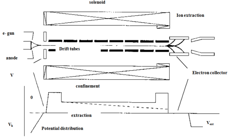 | Figure 12. Elements of EBIS ion source with potential distribution |
7 Laser Beam Ion Sources (LBIS)
- The laser induced plasma from a solid target is based on the use of powerful laser (power 1010-1013 W/cm) producing a short beam in a nanosecond range (Fig.13). This powerful laser will be focused on a target made from (Li, LiF, C, Zi, and Ta). Ions in the plasma have a mixture of charge states and energies and the major problem in the laser ion source is the extraction of the desired ion species as a beam of reasonable characteristics. Principle of operation of the laser ion source is based on plasma generation by a laser beam focused by a mirror system (lens) on a solid movable target. The focused laser light is used to evaporate particles from a target which is made out of the material to be ionized. The electrons of the plasma, which is generated during the evaporation process, are heated by the laser radiation to temperatures up to several hundreds of eV. The ions are ionized due to electron- ion collisions. The temperature of the plasma and the final ion charge state distribution are strongly depend on the laser power density on the target. The first operation of a laser ion source based on Nd-glass on a cyclotron machine was reported by Ananin48: Laser ion sources for Van-de-Graaf accelerators have been employed at the Technical University of Munich4 and at ITEP-Moscow4:
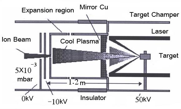 | Figure 13. Main elements of LBIS ion source |
8. Conclusions
- In the present work, different types of multicharged ion sources with their applications have discussed and reviewed. In all types of multicharged ion sources, the ions are produced by various types of gas discharge including electron collisions with gas particles. Criteria for production of multicharged ion beams are studied. In further consequence, our research work was quickly described, reviewed and gave some results showing the importance in some areas of applications.