-
Paper Information
- Next Paper
- Previous Paper
- Paper Submission
-
Journal Information
- About This Journal
- Editorial Board
- Current Issue
- Archive
- Author Guidelines
- Contact Us
Science and Technology
p-ISSN: 2163-2669 e-ISSN: 2163-2677
2012; 2(4): 77-80
doi: 10.5923/j.scit.20120204.04
An Investigation of Thermal Performance of Heat Pipe Using Di-water
 Abstract
 Reference
 Full-Text PDF
 Full-Text HTML
R. Manimaran 1, K. Palaniradja 1, N. Alagumurthi 1, K. Velmurugan 2
1Department of Mechanical Engineering, Pondicherry Engineering College, Puducherry, India
2Department of mechanical Engineering, Sri Manakula Vinayagar Engineering college, puducherry, India
Correspondence to: R. Manimaran , Department of Mechanical Engineering, Pondicherry Engineering College, Puducherry, India.
| Email: |  |
Copyright © 2012 Scientific & Academic Publishing. All Rights Reserved.
Heat pipes are two-phase heat transfer devices with high effective thermal conductivity. The performance of the heat pipe is greatly depends on the filling ratio of the working fluid. An experimental set up was made from a copper tube with an inner diameter of 20.8 mm and outer diameter 22 mm. The Di-water is used as a working fluid. The temperatures at different places on the heat pipe were measured including the temperature of inlet and outlet of the cooling water. The results indicate that the variation of filling ratio, heat input and angle of inclination has a significant effect on its performance.
Keywords: Heat Pipe, Efficiency, Angle of Inclination, Fill Ratio
Article Outline
1. Introduction
- Air cooling solution which comprises a fan and heat sink is employed to remove heat generated by electronic device for stability and lifespan[1]. To solve the growing heat generated by electronic devices, two-phase change devices (e.g. heat pipe, loop heat pipe, thermosyphon cooling system) become main cooling technologies in the electronic industry[2]. Heat pipes are two-phase heat transfer devices with high effective thermal conductivity. Due to the high heat transport capacity, heat exchanger with heat pipes has become much smaller than traditional heat exchangers in handling high heat fluxes. With the working fluid in a heat pipe, heat can be absorbed on the evaporator region and transported to the condenser region where the vapour condenses release the heat to the cooling media[3]. Heat pipe technology has found increasing applications in enhancing the thermal performance of heat exchangers in microelectronics, energy saving in HVAC systems for operating rooms, surgery centres, hotels, clean rooms, temperature regulation systems for the human body and other industrial sectors.Heat pipes play an important role in almost all industrial fields as an effective heat transfer element. Heat pipe is an evaporation-condensation device for transferring heat in which the latent heat of vaporization is exploited to transport heat over long distances with a corresponding small temperature difference. The heat transport is realized by means of evaporating a liquid in the heat inlet region (called the evaporator) and subsequently condensing the vapour in a heat rejection region (called the condenser). Closed circulation of the working fluid is maintained by capillary action and /or bulk forces[4]. The heat pipe was originally invented by Gaugler of the General Motors Corporation in 1944, but did not truly garner any significant attention within the heat transfer community until the space program resurrected the concept in the early 1960’s[5]. Pastukhov et al.[6], experimentally investigated the performance of a loop heat pipe in which the heat sink was an external air-cooled radiator. The study showed that the use of additional active cooling in combination with loop heat pipe increases the value of dissipated heat upto 180 W and decreases the system thermal resistance down to 0.29 K/W. An advantage of a heat pipe over other conventional methods to transfer heat such a finned heat sink, is that a heat pipe can have an extremely high thermal conductance in steady state operation. Hence, a heat pipe can transfer a high amount of heat over a relatively long length with a comparatively small temperature differential. Heat pipe with liquid metal working fluids can have a thermal conductance of a thousand or even tens of thousands of times greater than the best solid metallic conductors, silver or copper. A pressure difference is created in the liquid-saturated wick due to the difference between the capillary radii in the evaporator and condenser ends of the wick structure which drives the liquid from the condenser section to the evaporator section through the wick structure and hence the overall process becomes continuous[7].Fluids used in heat pipes have high-surface-tension because they provide the necessary capillary pumping and wetting characteristics for better operation. The required thermophysical properties of fluids used in heat pipes include a high liquid thermal conductivity, high latent heat of vaporization, low liquid viscosity, and a low vapor viscosity[8].The properties of the material and structural characteristics of heat pipe wick structures are a high thermal conductivity, high wick porosity, small capillary radius, and high wick permeability[8].
 | Figure 1. Schematic view of heat pipe |
2. Experimental Setup
- A copper tube was used for test section with an internal diameter of 20.8 mm and external diameter of 22 mm.Two layers of stainless steel screen mesh wick has been used to improve the capillary action. The length of the evaporator, adiabatic and condenser sections are 150,300 and 150 mm respectively.
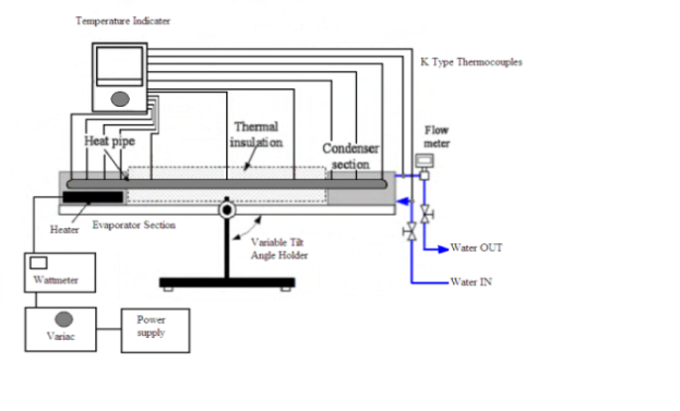 | Figure 2. Schematic diagram of experimental setup |
3. Results and Discussion
- Experiments were carried out using Di-Water as a working fluid; the heat pipe is tested for various angle of inclination, different fill ratio and for different heat inputs. The temperature gradient along the heat pipe axis increases with increase in heat input and the temperature difference across the condenser and evaporator section is larger.
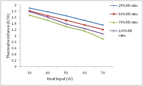
3.1. Effect of Fill Ratio on the Thermal Resistance of Heat Pipe
- The thermal resistance represents the effectiveness of the heat pipe .The R can be represented by
 | (1) |
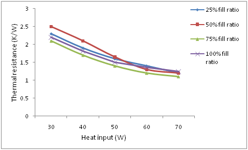 | Figure 3. Thermal resistance for different heat input and fill ratio for 00 degree inclination |
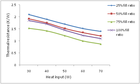 | Figure 4. Thermal resistance for different heat input and fill ratio for 300 inclination |
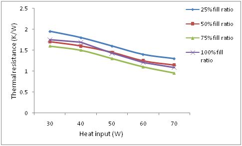 | Figure 5. Thermal resistance for different heat input and fill ratio for 600 inclination |
 | Figure 6. Thermal resistance for different heat input and fill ratio for 900 inclination |
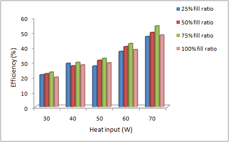
3.2. Effect of Fill Ratio on the Heat Pipe Efficiency
- Fig.7-10 shows the variations of thermal efficiency of heat pipe for different heat input and fill ratio. It can be seen that the thermal efficiency of the heat pipe increases when the fill ratio increases and reaches the maximum value when the fill ratio is 75% and shows a decline in efficiency for further rise in fill ratio. When the fill ratio is low the fluid at the evaporator section is vapoursied at a faster rate when the heat input is given and the condensation occurs at a lower rate due to the accumulation of more vapour at the condenser section which leads to dry out phenomenon at the evaporator section and hence the lower efficiency occurs. When the fill ratio is higher the temperature at the evaporator section is lower and hence the evaporation occurs at a lower rate, as a result very little vapour is flown into the condenser section thus reducing the thermal efficiency of the heat pipe. The heat pipe reaches maximum efficiency when the angle of inclination is 300 and 70W heat input. This is because the gravitational force has a significant effect on the flowing of the working fluid between evaporator section and condenser section.
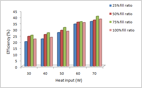 | Figure 7. Efficiency for different fill ratio and heat input at 00 degree inclination |
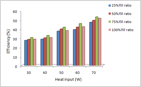 | Figure 8. Efficiency for different fill ratio and heat input at 300 degree inclination |
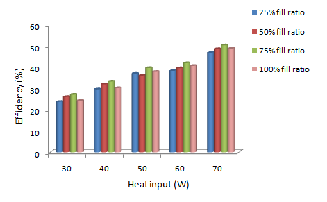 | Figure 9. Efficiency for different fill ratio and heat input at 600 degree inclination |
 | Figure 10. Efficiency for different fill ratio and heat input at 900 degree inclination |
4. Conclusions
- Experiment has been conducted on the heat pipe using Di-water as a working fluid to analyse the thermal performance of the heat pipe under various operating parameters such as heat input, fill ratio and angle of inclination. The thermal resistance decreases as the angle of inclination increases and reaches a minimum value when the heat pipe is in vertical position and the fill ratio is 75%. Also an optimum efficiency value is obtained when the heat pipe is operated with 75% fill ratio for an angle of inclination 300 .