-
Paper Information
- Next Paper
- Previous Paper
- Paper Submission
-
Journal Information
- About This Journal
- Editorial Board
- Current Issue
- Archive
- Author Guidelines
- Contact Us
Science and Technology
p-ISSN: 2163-2669 e-ISSN: 2163-2677
2012; 2(1): 47-50
doi: 10.5923/j.scit.20120201.09
Lean Combustion Technology for Internal Combustion Engines: a Review
 Abstract
 Reference
 Full-Text PDF
 Full-Text HTML
Danaiah P. , Ravi Kumar P , Vinay Kumar D.
National Institute of Technology, Warangal, India
Correspondence to: Danaiah P. , National Institute of Technology, Warangal, India.
| Email: |  |
Copyright © 2012 Scientific & Academic Publishing. All Rights Reserved.
Lean burn is an effective way to improve spark ignition engine fuel economy. Lean combustion is generally considered as a timely solution to the more stringent environmental regulations and global weather concerns in the new era. However, the instability associated with the lean flame significantly keeps the lean combustion technique from being widely accepted as a major combustion technique for general applications. A comprehensive study has been made in this report on the investigations of various researchers and research organizations on the lean combustion technology as well as to give a review of the work which has recently been performed in the area of lean combustion.
Keywords: Lean Burn, Engine Fuel Economy, Spark Ignition
Cite this paper: Danaiah P. , Ravi Kumar P , Vinay Kumar D. , "Lean Combustion Technology for Internal Combustion Engines: a Review", Science and Technology, Vol. 2 No. 1, 2012, pp. 47-50. doi: 10.5923/j.scit.20120201.09.
Article Outline
1. Introduction
- Before 1970’s a very few attempts were made to study on the lean combustion technology in SI engines with experimentally. This technology was studied first during 1908 to demonstrate the advantages of higher thermal efficiency [1, 2].Later on the need for emission control became evident and hence the lean combustion technology shows to offer the lower emissions and also improves the fuel economy[2-4].As a matter of fact the lean combustion engines have long been established to improve the fuel economy and lower emissions. However the raising of prices, uncertainties in the supply of petroleum products have forced to focus attention on the problems of lean mixture combustion in SI engines.
2. Lean Limit through Increased Turbulence Generation
- Semenov’s (1963)[5] explained that the turbulent gas flow in piston engines is regarded as fundamental. Hotwire anemometry (HWA) studies in a motored engine with a flat top piston showed that shear flow through the intake valve was the primary source of turbulence generation. In most cases, however, much of the turbulence generated during the intake stroke decays before the combustion process is started. Squish-generated turbulence, on the other hand, is generated during the last phase of the compression stroke, just before it is most needed to influence the combustion process.Heywood (1988)[6] has shown that turbulence generation by combustion chamber design, with an emphasis on squish, should provide a fast-burn rate for high efficiency and good emission control. He also noted that the chambers should be geometrically simple, and practical to manufacture.
3. Comparison of Squish and Swirl Effects
- Goetz et al. (1993)[7] performed the experiments for designing and comparing the effectiveness of the UBC squish-jet design in comparison to a high swirl design during lean operation by using a single-cylinder version of the Cummins L-10 engine are shown in Figures 1 and 2
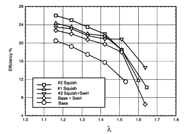 | Figure 1. Variation of Efficiency verses λ |
 | Figure 2. Variation of NOx versus efficiency trade- off |
4. Partial Stratified Engine
- Evans et al. (1996)[8] modified spark plug used to implement the PSC system as shown in Figure 3. In this, passage was drilled in the metal cladding of the spark plug to accommodate a small section of capillary tubing used to introduce the pilot fuel. The capillary tube connects to a fine slot in the threads, and ultimately the PSC fuel is delivered through a very small hole into the space around the ground electrode of the plug. The PSC system uses a high-pressure natural gas line (200 bar), which is regulated to lower pressures (around 20–50 bar) to supply the spark-plug injector mounted in the research engine.
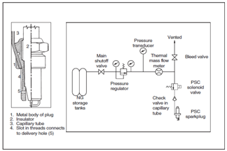 | Figure 3. The PSC spark-plug-injector and system schematic |
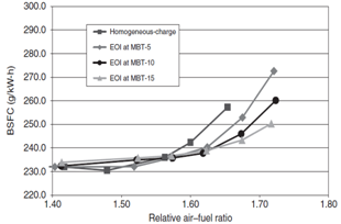 | Figure 4. BSFC versus relative air fuel ratio λ, 2500 rpm |
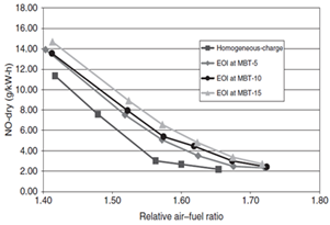 | Figure 5. NOx versus relative air fuel ratio λ, at 2500 rpm |
5. Toyota Lean Burn Engine
- Noguchi et al[11] have developed the Toyota lean burn engine in the year 1976 which is provided with a pre-chamber where the fresh air-fuel mixture flows through an orifice during the compression stroke resulting in strong eddies of mixture with in the pre-chamber. A spark plug located at the orifice ignites a flame kernel in the mixture flow and causes the rapid combustion in the pre-chamber. As a result, the jet of flame shoots out into the main chamber where it ignites the lean mixture. This pre-chamber is called the turbulence generating pot (TGP). In addition to this, the carburettor and exhaust manifold are modified for a lean operation. The compression ratio used was 8.5 and 9 with the volume of TGP being 4.6cc to 10.4cc, forming 2.2% to 4.9 % of the total combustion volume. The diameter of the connecting orifice is 8.5mm to17mm.
6. Fireball Combustion Chamber Engine
- Michal G May[12] has developed the fireball combustion chamber engine which consists of a compact combustion and has claimed successful operation with homogeneous mixture of air fuel ratio around 26:1. In this engine, the exhaust valve is recessed into a combustion chamber which is in the shape of small bath tub. The remaining surface, including that of the inlet valve, is flat and virtually flush with the cylinder head faces and functions as a wide squish area. This geometry induces a high swirl at about 10 to 20 degrees btdc. A looping flow pattern results and rotating charge is concentrated in the open recess, where it is ignited by a spark plug located in one corner and burns very rapidly. This configuration allows the use of a high compression ratio without the risk of pre-ignition and knocking. A high thermal efficiency and more complete combustion are thus achieved. Both fuel consumption and emissions are reduced.
7. Lean Burn Pre-Chamber Engine
- Walfer Brand Stetter[13] developed a simpler, but very effective concept, that of a lean burn pre-chamber (PC) engine in order to meet the future emissions and fuel economy standards for European countries. A large part of his experimental work dealt with fuel-air mixture formation, distribution and heating. A simple means of exhaust gas after treatment was also considered in this concept. He compared this newly developed engine with his own earlier version of pre-chamber injection (PCI) stratified charge engine with a divided combustion chamber and fuel injection into the pre-chamber. He has claimed a significant improvement in mixture distribution between cylinders eve during cold operation. The emissions were reduced by approximately 30% with a simple thermal reactor. With the PC concept exhaust emissions of 25 g of CO per test and 9 g of HC and NO per test and a fuel consumption of 11.9,1 per 100 km run could be obtained when the European driving style was followed.
8. Pre-Chamber Torch Ignition
- T.G. Adam[14] has developed an engine which has a combustion chamber of a simple design called the pre- chamber torch ignition. It is claimed that the average CO content in the exhaust gas can be reduced to less than 0.5%. Some simple calculations to find optimum torch volume and the orifice diameter have also been developed for this engine. The experimental results have shown significant reduction HC and NOᵪ produced in the combustion process could be reduced by the use of torch nozzle to control the burning rate, which I turn would affect the peak temperature ad its duration and hence the NOᵪ formation.
9. Tornado Chamber
- Herbsleb et al[15] of Demark investigated the lean combustion of a homogeneous air fuel mixture in a special type of combustion chamber called, Tornado chamber and could get a lean operation of about 24:1and an improvement in specific fuel consumption (SFC) of about 5% compared to that of the Heron type combustion chamber. In this engine, the combustion chamber is located on the top of the piston. In order to produce a high swirl near TDC and achieve faster combustion two pockets with a connecting channel were formed.
10. High Compression Ratio Compact Chambers
- The use of a high compression ratio compact combustion chamber was investigated by Thring and Overington[16], with an objective of improving fuel economy with in a given set of exhaust emission constraints. The effects of the parameters such as swirl, compression ratio, combustion chamber geometry and its location were investigated. It was found that varying the rate of swirl of the charge would have a significant effect on the octane requirement, fuel economy and exhaust emissions. The optimum swirl ratio was found to be 0.3. It made very little difference with the location of the chamber in the cylinder head or in the piston, except that HRCCC in the piston was not so good with fuels of low Research octane Numbers (RON). A 6% improvement in fuel economy was claimed when the HRCCC concept was used in a four cylinder engine. The best compression ratios were about 13:1 for Europe and about 11:1for the USA and Japan.
11. Swirl Produced By Intake Port
- Richard Belaire et al[17] in their work, using a cylinder head with a swirl producing, intake port (75% and 60% squish bowl in the piston chambers and a disk chamber) experimental measurements of burn rates were carried out in a single cylinder, homogeneous charge engine. Three different combustion chambers were investigated. The data was obtained with each combustion chamber under variation of spark timing, exhaust gas recirculation and load at 1500 rpm. It was concluded that the combustion rate was strongly influenced by the chamber shape. The 10-90%burn duration of the 75% and 60% squish chambers were respectively about 40% and 60% that of the disc chamber. Chamber configuration had less effect on 0-10%burn time than the bowl in the piston chambers.
12. High Compression Lean Burn Engine
- Sutton[18] carried out experimental investigations on three types of combustion chambers. The combustion chamber was provided below the exhaust valve and below the inlet valve in two different engines. The performance of these chambers was compared with the standard combustion chamber. Test results have shown that the best performance was obtained with the high compression lean burn engine (HCLBE) design with the main combustion space under the inlet valve, arranged to promote a high degree of induction swirl. Faster burning of the combustion charge gave significantly improved knock free performance and increased the engine efficiency.
13. Lean-Burn Engine - Potential Analysis
- Analysis of the thermodynamic cycle of IC engine[19] from the point of view of economy and emissions was carried out. From this analysis potential capability of engine development was derived. This potential capability is lean burn engine, fuelled with homogeneous mixture with λ ≥ 1.4. Several different modes of fuelling were proposed and tested on one-cylinder test engine from the point of view of extending lean operating limit of the engine, emissions and fuel economy. Among them were: fuelling with evaporated preheated gasoline, with gas (LPG evaporated) and with liquid butane. From these modes, fuelling with liquid butane injected to inlet port was selected and finally tested.
14. Conclusions and Future Work
- In this paper several techniques on lean combustion technology have been studied and Future work includes validation of suitability of the techniques for operation under the different compression ratios with the influence of ignition energy and by using different alternative fuels.AbbreviationsHWA: Hotwire anemometryPSC: partially stratified-chargeBSFC: Brake specific fuel consumptionPC: pre-chamberPCI: pre-chamber injectionSFC: Specific fuel consumptionRON: Research octane NumbersHCRCC: High Compression Ratio CompactChambersHCLBE: high compression lean burn engine