-
Paper Information
- Paper Submission
-
Journal Information
- About This Journal
- Editorial Board
- Current Issue
- Archive
- Author Guidelines
- Contact Us
Journal of Safety Engineering
p-ISSN: 2325-0003 e-ISSN: 2325-0011
2017; 6(1): 8-13
doi:10.5923/j.safety.20170601.02

The Use of a Pneumatic Horizontal Impact System for Helmet Testing
 Abstract
 Reference
 Full-Text PDF
 Full-text HTML
Leigh Jeffries , Carlos Zerpa , Eryk Przysucha , Paolo Sanzo , Stephen Carlson
School of Kinesiology, Lakehead University, Thunder Bay, Canada
Correspondence to: Carlos Zerpa , School of Kinesiology, Lakehead University, Thunder Bay, Canada.
| Email: |  |
Copyright © 2017 Scientific & Academic Publishing. All Rights Reserved.
This work is licensed under the Creative Commons Attribution International License (CC BY).
http://creativecommons.org/licenses/by/4.0/

Helmets are the main form of head protection used in the sport of hockey and have proven to be effective in minimizing linear accelerations applied to the head during impact. Unfortunately, head and brain injuries still continue to occur posing a significant threat to the health and safety of ice hockey players. The primary form of evaluating hockey helmets' performance is through the simulation of head impacts using impactors and anvils to measure acceleration during a free-fall mechanism. This method of assessment, however, does not closely emulate on ice head impacts to study injury mechanisms believed to be responsible for mild traumatic brain injuries and concussions. Based on this concern, there is a need to develop new impactors to further simulate and study mechanisms of injury in ice hockey. Evidence of reliability and validity for the use of these impactors’ acceleration measures is always needed before using these devices to accurately simulate head impact injuries and conduct further research. The purpose of this study was to provide evidence of reliability and validity for the use of a new pneumatic helmet impact system to measure horizontal linear impact acceleration before conducting helmet testing research. The results provide strong evidence of reliability (ICC = .79-.88, p < .0001) in measuring linear horizontal accelerations applied to the head across impact locations. The results also provide concurrent-related evidence of validity (ICC=.85-.95, p < .0001) when comparing the new pneumatic helmet impact system to a standardized drop head impact system. These outcomes suggest that the new impactor system can be used to accurately and consistently measure linear acceleration in future research.When introducing a new impactor and testing protocol to assess helmet performance, it is necessary to comply with the National Operating Committee on Standards for Athletic Equipment (NOCSAE) and provide evidence of reliability and validity for the use of the instrument measures [15]. Reliability refers to the consistency of a test or measurement measures across repeated trials [17]. The split-half method estimates reliability across repeated trials by creating two parallel subsets of equal size from one sample, then correlating even and odd scores to provide an estimate of the instrument’s reliability [16]. Validation of the instrument measures, on the other hand, can be obtained by providing concurrent-related evidence of validity. That is, the degree to which instrument measurements are correlated with another relevant instrument measure or standard as the primary test of interest [16]. Based on this premise, the purpose of this study was to provide evidence of reliability and validity for the use of a new pneumatic helmet impact system to measure horizontal linear impact acceleration to assess helmet performance.
Keywords: Concussion, Helmet Impact System, Impact Biomechanics
Cite this paper: Leigh Jeffries , Carlos Zerpa , Eryk Przysucha , Paolo Sanzo , Stephen Carlson , The Use of a Pneumatic Horizontal Impact System for Helmet Testing, Journal of Safety Engineering, Vol. 6 No. 1, 2017, pp. 8-13. doi: 10.5923/j.safety.20170601.02.
Article Outline
1. Introduction
- Ice hockey is a high-speed collision sport with an inherent risk of injuries [1]. Most concerning of all injuries are the ones to the head and brain, which can lead to severe neurological dysfunction and even death [2]. Head injuries are commonly the result of traumatic brain injuries (TBI). A TBI is caused by a sudden impact causing acceleration-deceleration trauma of the head and may range from mild (mTBI) to severe [3]. Brain injuries can also be categorized as focal or diffuse. Focal brain injuries (e.g., skull fractures, hematomas), relate to damage to a specific location of the brain under the site of impact [4], resulting in focal neurological deficits specific to that area [5]. Diffuse head injuries (e.g., concussion), relate to damage to a more widespread or global disruption of neurological dysfunction and are not typically associated with macroscopically visible brain lesions [5]. Both types of injuries can possibly occur from a single impact.Helmets are the primary form of head and brain protection for hockey players to prevent injuries [2]. Research has shown that helmets have been effective in reducing head impact forces involved in skull fractures [6]. There is little evidence to support, however, that helmets are as effective at preventing mTBI or concussions from biomechanical forces applied to the head or torso [6]. One of the reasons may be that helmet designs and performance are being compromised for comfort and appearance [7]. Even with the mandatory wearing of helmets, head and brain injuries continue to increase in the sport of hockey. Concussions or mTBIs, for example, have been identified as one of the most common injuries in hockey with the highest occurrence per participant of all sports [8]. Recent concussion rates in ice hockey have been calculated to be 1.4 per 1000 player-games at the international [9] and collegiate levels [10]. This high rate of concussion injuries suggest that further development of helmet technology and testing protocols are needed. Current helmet testing and evaluation protocols entail a pass or fail criteria based on a single and large impact [2]. Helmet testing is conducted by using a surrogate headform with a helmet mounted on it. The headform is instrumented with an array of accelerometers and it is designed to respond similarly to an actual human head during impact [11]. Peak linear accelerations felt by the headform at impact are used to assess the ability of the helmet to protect the head against brain injuries and assess the injury risk [2, 12]. The maximum protocol value of linear acceleration allowed during helmet testing to protect the head against a brain injury is 275-300g from a drop height of 1.5 meters. This value was obtained from skull fracture data of human cadaver research and it is considered an acceptable threshold value to assess the pass or failure of a helmet [13]. If the peak linear acceleration value is less than the threshold value during the impact, the helmet is deemed appropriately protective. The unit “g” is used for any linear acceleration analysis and is a multiple of the acceleration due to gravity (g = 9.81m/s2).While current standard helmet testing protocols entail the use of surrogate headforms instrumented with linear impact accelerometers and a free-falling drop mechanism (designed to strike a flat surface without head movement after impact), some injury mechanics in ice hockey occur horizontally with a head movement after impact [14]. In order to study injury mechanisms due to horizontal impacts, there is a need to develop impactors, instrumented with a headform free to move post impact to more closely emulate on ice hockey players' collisions [14]. This approach may provide an avenue to help improve hockey helmet testing standards and possibly reduce the risk of head injuries [13].
2. Methods
2.1. Hypotheses used to Guide the Study
- a) Evidence of reliability: It was hypothesized that there would be a strong correlation across trial replications on peak linear acceleration measures for each helmet impact location.b) Evidence of concurrent validity: It was hypothesized that there would be a strong correlation between the vertical and horizontal impactors’ linear accelerations measures across helmet locations when hit at the velocity of 4.39 m/s.
2.2. Instruments
- Pneumatic linear impactor used in this study. This impactor consists of a main frame, impactor rod, and linear bearing table as depicted in Figure 1. The main frame is a welded steel structure secured to the floor. The main frame contains the compressed air tank, air cylinder, air release valve, impactor rod, and linear bearing table. The air cylinder propels the impact rod with velocities up to 7m/s by discharging the air pressure via a control valve from the 3-gallon compressed air tank. The air pressure is monitored using a MGA-100-A digital pressure gauge (SSI Technologies, Inc.) with an accuracy of ± 1%. The mass of the impacting rod is 13.1kg, and it is propelled horizontally when the compressed air is released. The head of the impacting rod consists of a 7.4cm (diameter) by 2.7cm (thick) cylindrical nylon pad attached to a 7.4cm long metal disc. This impactor head is slightly different than the impactor heads outlined by NOCSAE standards [18].
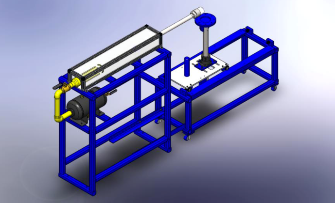 | Figure 1. Schematic of the new pneumatic linear impactor |
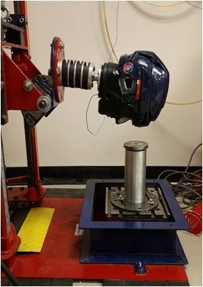 | Figure 2. Vertical dual rail drop system with headform mounted on drop carriage and positioned to contact the impact anvil |
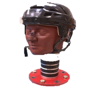 | Figure 3. NOCSAE headform fitted with hockey helmet and mounted on mechanical neckform |
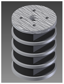 | Figure 4. Mechanical neckform assembly |
2.3. Procedures and Analyses
- This study included front, rear, and side helmet impact sites. All sites were hit at an angle perpendicular to the headform surface location, with no vertical or horizontal rotation being applied to the impact vector. The three impact sites were defined as: (1) the anterior intersection of the mid-sagittal and absolute transverse planes, (2) the right intersection of the coronal and absolute transverse planes, and (3) the posterior intersection of the mid sagittal and absolute transverse planes. These three sites were selected for testing because upon impact, they have been found to sustain higher average g-accelerations, and be linked to an increased risk of injury [20].Before collecting helmet impact data from each vertical and horizontal impactor across the three impact sites, NOCSAE standards [12] were used to fit a hockey helmet to the surrogate headform. The helmet testing protocol was further standardized by ensuring a 5.5cm distance from the brim of the helmet to the bridge of the nose on the headform. The head was then positioned and secured to either the front, side, or rear impact location. To achieve the impacts on the new pneumatic linear impactor, the compressed air tank was pressurized to 40psi. Once the pressure was achieved, a manual control valve was open and the air pressure was released, propelling the impact rod into the impact site at an average speed of 4.39m/s. To achieve identical impacts when using the standardized vertical drop rig, the drop carriage was raised to a height of 0.98m and dropped onto the impact anvil.For each impact location on the helmet, the linear acceleration data (x, y, and z directions) were acquired by the accelerometer sensors mounted in the headform. The data were fed into an analog to digital amplifier unit and processed via a commercial software package called POWERLAB.Resultant linear acceleration was computed using the POWERLAB software calculation module based on Equation 1:
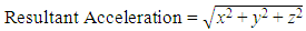 | (1) |
3. Results
3.1. Reliability
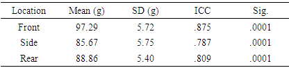
- The results depicted in Table 1 provide a summary of the peak linear acceleration measures obtained from 100 impacts to the front, side, and rear locations when hit by the horizontal impactor rod propelled with a pressure of 40psi. The front location had the highest mean peak linear acceleration (M=97.29g, SD=5.72g) when compared to the side (85.67g, SD=5.75g) and rear (M=88.86g, SD=5.40g) locations. The results also provide evidence of reliability as strong significant intraclass correlation coefficients (ICC) were found across replications for the front (r=0.86, n=50), side (r=0.79, n=50), and rear (r=0.81, n=50) impact sites respectively.
|
3.2. Validity
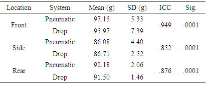
- The results in Table 2 provide a summary of the mean peak linear acceleration measures across impact locations for the vertical and horizontal impactors when used under the same impact testing protocol. The results also provide evidence of concurrent-validity when comparing the acceleration measures of the new pneumatic linear horizontal impactor to the acceleration measures of the vertical standard drop system. This evidence of validation was revealed by strong significant intraclass correlations between the acceleration measures obtained from both systems on the side (r=0.85, n=25), front (r=0.95, n=25), and rear (r=0.88, n=25) helmet impact locations.
|
4. Discussion
- The results of the current study provide strong evidence of reliability and validity across all impact locations as depicted in Table 1 and 2. It can be noticed, however, that the side location produced a lower correlation coefficient across replications when compared to the front and rear locations. Similar patterns can be observed across validation of the side location when comparing the acceleration measures between the vertical and horizontal impacts. As stated in previous research [7], one of the reasons for this outcome, may be that the side location behaves differently in minimizing impact accelerations as compared to other helmet locations due to the geometry of the helmet. Human error can also play a role in reliability and validity measures as any small discrepancy in repositioning the helmet before each impact on the side location or any other helmet location can translate into a change in neck torque and, consequently, a change in linear impact acceleration. Human error was minimized in the current study by following the NOCSAE standards and using the same researcher to reposition the helmet before each impact. It is also important to consider that NOCSAE standards specify that pneumatic ram impactors can propel the impactor arm at ± 2% of the specified velocity, which can also translate into small but not significant differences on acceleration measures across replications and between impactors. Reliability and validity measures could have also been affected by the use of a manual control valve to release the pressure and propel the horizontal impactor arm. Although the researcher who collected the data tried to open the valve consistently each time, there is still the possibility of additional human error being introduced in the measurement. Future research studies will include the use of an electronic solenoid valve. A solenoid valve is a device actuated by a solenoid, for controlling the flow of gases in pipes [21]. This device will automatically release the air pressure to propel the horizontal impactor arm to acquire higher consistency during data collection. Regardless of this limitation, the result indicate that the new horizontal impact system is comparable to a standard NOCSAE drop system when tested under the same impact protocol. This evidence of validation in combination with the reliability measures indicate that the system can be used for research on helmet impact testing. Future research will entail the use of this impactor to simulate and study head impact injury mechanisms and energy dissipation measures across helmet impact locations.
5. Conclusions
- The purpose of this study was to provide evidence of reliability and validity for the use of a new pneumatic impactor when measuring peak linear acceleration. The findings of this study provide evidence that the new horizontal impactor acceleration measures are reliable and valid to conduct further research for helmet testing and simulated injury reconstruction in hockey or other sports. The outcomes may also have implications on helmet design and standards for impact testing.
ACKNOWLEDGMENTS
- The researchers would like to thank the senior engineering students from the Mechanical Engineering Department at Lakehead University for designing and building the impactors. The researchers would also like to thank Glen Patterson for his technical expertise in calibrating the impactors.